SCS TB-9115 User manual

TB-9115 Page 1 of 6 © 2023 DESCO INDUSTRIES INC
Employee Owned
Desco Asia - 193-12 Yachimata-i, Yachimata-shi, Chiba, 289-1143, Japan
Phone: +81 43-309-4470 • Website: DescoAsia.com
975 Ionized Air Blower
Installation, Operation, and Maintenance
June 2023
Description
The SCS 975 Ionized Air Blower is used for neutralizing
electrostatic charges on insulators and ungrounded
conductors. Its fast discharge times (< 1 second at 12
inches) and ±10 volt offset voltage exceed the required
limits of ANSI/ESD S20.20 and ESD TR53. The 975
Ionized Air Blower monitors its offset voltage (balance),
and it alarms when emitter cleaning is required. A
built-in automatic emitter point cleaner periodically
brushes away dust and minimizes maintenance. The
emitters may be accessed for thorough cleaning with
the use of a single thumb screw. The 975 Ionized Air
Blower features a powder coated steel enclosure,
multi-mount stand, and terminal block with alarm output
for machine integration.
The SCS 975 Ionized Air Blower operates on
Steady-state DC. Steady-state DC systems consist of
separate negative and positive ion emitters connected
by a pair of high-voltage cables to their respective
high-voltage power supplies. DC power is constantly
applied to the emitter points. The ionizer utilizes
sampling from its inner fan grill to continuously adjust
the output and maintain its offset voltage.
USER GUIDE TB-9115
“The primary method of static charge control is direct
connection to ground for conductors, static dissipative
materials, and personnel. A complete static control
program must also deal with isolated conductors
that cannot be grounded, insulating materials (e.g.,
most common plastics), and moving personnel who
cannot use wrist or heel straps or ESD control flooring
and footwear. Air ionization is not a replacement for
grounding methods. It is one component of a complete
static control program. Ionizers are used when it is not
possible to properly ground everything and as backup
to other static control methods. In clean rooms, air
ionization may be one of the few methods of static
control available.” [ESD Handbook ESD TR20.20
Ionization, section 5.3.6.1 Introduction and Purpose /
General Information]
The 975 Ionized Air Blower and its accessories are
available as the following item numbers:
Item Description
975A Ionized Air Blower with North America
Power Adapter
975N Ionized Air Blower without Power Adapter
975P North America Power Adapter
Packaging
1 Ionized Air Blower
1 Ground Wire
1 Power Adapter (975A only)
1 North America Power Cord (975A only)
1 Certificate of Calibration
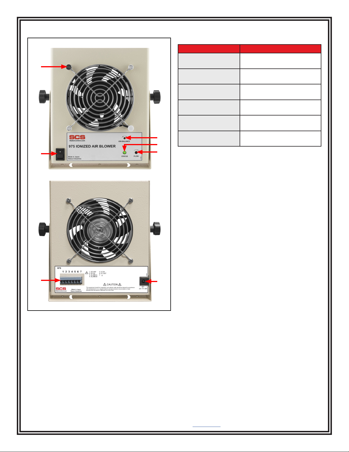
Figure 1. SCS 975 Ionized Air Blower
Made in Japan

TB-9115 Page 2 of 6 © 2023 DESCO INDUSTRIES INC
Employee Owned
Desco Asia - 193-12 Yachimata-i, Yachimata-shi, Chiba, 289-1143, Japan
Phone: +81 43-309-4470 • Website: DescoAsia.com
D. Status LED: Provides 6 different indications. See the
table below.
Indicator Status
Green Normal operation
Blinking orange once
per 1.6 seconds
Maintenance needed or ion
balance dial is not set to 0V
Blinking red once per
1.6 seconds
Fan does not rotate
Blinking red twice per
1.6 seconds
High-voltage module failure
Blinking red three
times per 1.6 seconds
Ion balance out of control
Blinking red four times
per 1.6 seconds
Drive failure in emitter point
cleaner
E. Fan Speed Dial: Use a Phillips-head screwdriver to
rotate the dial clockwise to increase the fan speed or
counterclockwise to decrease the fan speed.
F. Terminal Block: Wires to external power provided
by a machine and outputs an alarm signal. See
"Terminal Block Setup" on page 3 for more information.
G. Power Inlet: Connect the included power adapter
here.
Installation
Hardware Setup
Install the included ground wire to Terminal 7 at the
back of the ionizer. Connect the opposite end of the
wire to equipment ground. Place the 975 Ionized Air
Blower at a desired location where the airflow will not be
restricted. Ensure a space of at least 4 inches (10 cm)
at the rear and on both sides of the ionizer to provide
sufficient airflow. Use the tilt lock knobs to aim the
ionizer at the area to be neutralized. Ensure that the
power switch is set to OFF. Connect the ionizer’s power
cord into an appropriate AC power source.
Note that placement of the ionizer is important in
determining its effectiveness. The distance from the
targeted object and fan speed affect the ionizer’s
performance. The discharge time will increase as the
distance increases or fan speed is reduced.
Features and Components
Figure 2. 975 Ionized Air Blower features and
components
FG
A
B
C
E
D
A. Fan Grill Thumb Screw: Loosens the fan grill, so
it may be swung to the side and grant access to the
emitter points for cleaning.
B. Power Switch: Powers the ionizer ON and OFF.
C. Ion Balance Dial: Use a flat-blade screwdriver to
rotate the dial clockwise to change the ion balance in
the positive direction and counterclockwise to change
the ion balance in the negative direction.

TB-9115 Page 3 of 6 © 2023 DESCO INDUSTRIES INC
Employee Owned
Desco Asia - 193-12 Yachimata-i, Yachimata-shi, Chiba, 289-1143, Japan
Phone: +81 43-309-4470 • Website: DescoAsia.com
Terminal Block Setup
Use insulated wires in 18-24 AWG size for wiring to the
terminal block.
Terminals 1 and 2 are for power input from a 24 VDC
supply when not using the included power adapter.
Terminals 3 and 4 are for alarm output. They are used
for open collector output (up to 30 V and 100 mA).
Current flows between terminals 3 and 4 (GND) on the
terminal block when an alarm is output.
Figure 3. Terminal block
Figure 4. Alarm open collector wiring diagram
Terminals 5 and 6 control the timing of the emitter
point cleaner. When multiple units are fed from the
same power supply, the rated power of the supply may
become insufficient if cleaning occurs simultaneously.
To avoid this situation:
• Prepare a power supply that can provide the total
power needed for simultaneous cleaning. Terminals
5 and 6 are not used in this case.
• Make connections between the terminal blocks on
multiple units to avoid a peak of power consumption
at one time by allowing cleaning to occur in
sequence. See below.
Connect the ionizers as shown below. This will make
Unit I work as a master and Units II, III, and IV as slaves
so that the four sets of emitter points are cleaned one
after the other.
Figure 6. Using the 975 Ionized Air Blower on a
workbench
Figure 7. Using the I975 Ionized Air Blower at a machine
station
Operation
1. Position the ionizer so that maximum airflow is
directed towards the items or area to be neutralized.
2. Rock the power switch to the ON position. The
status LED will illuminate green during normal
operation.
3. Set the fan speed dial to the desired setting. Higher
airflow will result in faster discharge times.
Figure 5. Wiring terminals 5 and 6 to multiple ionizers
Terminal 7 is for grounding the ionizer. Grounding is
required for optimal performance of the ionizer.

TB-9115 Page 4 of 6 © 2023 DESCO INDUSTRIES INC
Employee Owned
Desco Asia - 193-12 Yachimata-i, Yachimata-shi, Chiba, 289-1143, Japan
Phone: +81 43-309-4470 • Website: DescoAsia.com
Maintenance
Occasional cleaning of the case and of the ionizing
electrodes are the only routine maintenance procedures
required.
Cleaning the Enclosure
Wipe the enclosure with a soft cloth moistened with
water. If a stronger cleaning solution is required, mild
soap with water may be used. The use of any other
cleaning solutions is not recommended.
Cleaning the Emitter Points
CAUTION: Disconnect the power to the ionizer
whenever cleaning the emitter points.
When the emitter points become dirty, the internal
circuitry of the ionizer will be automatically adjusted to
emit an equal amount of positive and negative ions.
The automated brushes will keep the emitter points
clean by brushing them 8 times per cleaning cycle.
The cycle runs hourly. Particulates on the emitter point
may, however, inhibit ionization to a limited degree. The
emitter points are located behind the front grills. A jet
of clean, compressed air can be used to remove dirt
on emitter points. If a more rigorous cleaning method is
needed to remove particulate, clean the points with a
cotton swab dampened with isopropyl alcohol. Access
to the points is available through the front grill. Loosen
the thumb screw to disconnect the fan grill and swing it
to the side. Be careful not to damage the points during
cleaning.
Figure 8. Loosening the fan grill thumbscrew
Figure 9. Swinging the front fan grills to access the
emitter points inside the ionizer
Figure 10. Accessing the emitter points

TB-9115 Page 5 of 6 © 2023 DESCO INDUSTRIES INC
Employee Owned
Desco Asia - 193-12 Yachimata-i, Yachimata-shi, Chiba, 289-1143, Japan
Phone: +81 43-309-4470 • Website: DescoAsia.com
Calibration
The SCS 975 Ionized Air Blower is factory adjusted to
provide optimum performance. Further adjustment in the
field is not possible. However, the following instructions
can be followed to determine whether the Ionizer is
performing to specifications. The testing follows the
procedure outlined in the standard for Ionization, ANSI/
ESD STM3.1. Please refer to this standard for more
complete information.
Frequency of recalibration should be based on the
critical nature of those ESD sensitive items handled and
the risk of failure for the ESD protective equipment and
materials. In general, SCS recommends that calibration
be performed annually.
Periodically measure the balance and neutralization
times of the ionizer to verify that it is performing within
specifications. These measurements should be taken
using a charged plate monitor. Calibration should be
performed in accordance with the ESD Association
ionization standard ANSI/ESD STM3.1. With the
ionizer positioned a distance of 12 inches (30 cm), the
neutralization (discharge) time of ±1000V to ±100V
should be less than 1.5 seconds, and the balance
should be ±10V or better.
Neutralization (Discharge) Times
The comparative efficiency of bench top ionizers is
determined by a standard test published by the ESD
Association: ANSI/ESD STM3.1. Typical positive and
negative decay times (±1000V to ±100V) measured
using this standard are shown in Figure 11.
NOTE: All discharge times are in seconds and
representative only. They are not a guarantee. The
discharge times were recorded in a factory ambient
environment.
Specifications
Input Voltage and
Frequency
(External Adapter)
Power Input:
100-240 VAC, 50/60 Hz
Power Output:
24 VDC, 2.7 A
Power Adapter Cable Length:
5.0' (1.5 m)
Power Cord Length:
6' (1.8 m)
Operating Environment 50° to 104° F (10° to 40° C)
20 to 70% R.H.
Neutralization
(Discharge) Time at 12"
< 1 second
Oset Voltage
(Balance) at 12"
±10 V typical
Ion Emission Steady-state DC
Airow 128 CFM max. (3.63 m³/min)
Ozone <0.05 ppm
Power Consumption 20 W
Emitter Points Tungsten
Dimensions
(without stand)
7.9" H x 6.7" W x 2.8" D
(200 mm x 170 mm x 72
mm)
Weight 3.2 lbs (1.5 kg)
Country of Origin Japan
Figure 11. General dimensions of the 975 Ionized Air
Blower (mm)

TB-9115 Page 6 of 6 © 2023 DESCO INDUSTRIES INC
Employee Owned
Desco Asia - 193-12 Yachimata-i, Yachimata-shi, Chiba, 289-1143, Japan
Phone: +81 43-309-4470 • Website: DescoAsia.com
TP1 + >60
- >60
12" 12" 12"
12"
12"
TP4 +6.5
-6.7
TP7 +6.5
-7.3
TP10 +8.0
-9.5
TP2 +0.7
-0.9
TP5 +1.6
-1.9
TP8 +2.9
-3.5
TP11 +5.0
-5.7
TP3 + >60
- >60
TP6 +34.9
-32.9
TP9 +11.1
-12.1
TP12 +8.7
-9.0
975 Ionized
Air Blower
Air Flow
Charged Plate
12"
Figure 11. Neutralization (discharge) times in seconds
Limited Warranty, Warranty Exclusions, Limit of
Liability and RMA Request Instructions
See the Desco Asia Warranty -
DescoAsia.com/Limited-Warranty.aspx
Table of contents
Popular Blower manuals by other brands

Shindaiwa
Shindaiwa EB633RT Operator's manual

Meyer
Meyer 550 Series Installation, operation & maintenance instructions

Cocraft
Cocraft LB24 Original instructions

RedMax
RedMax HBZ260R Operator's manual

Black & Decker
Black & Decker BB600 instruction manual

EINHELL
EINHELL GE-EL 3000 E Original operating instructions