SDM PUSDM55A User manual

USER MANUAL
PUSDM55A (P550QVF07.0)
PUSDM65A (P650QVF09.0)
PUSDM75A (SN75UNM01.0)
V1.10

2| « Table Of Contents »
Table Of Contents
SAFETY INSTRUCTIONS...................................................... 4
Warnings..........................................................................................5
Power Management........................................................................6
Automatic Wake Up.......................................................................6
Recommended Use........................................................................7
Declarations ....................................................................................8
WHAT’S IN THE BOX............................................................ 9
Package Contents...........................................................................9
MOVING THE DISPLAY ....................................................... 10
Unpacking the Display .................................................................10
Carrying the Display ....................................................................13
Placing the Display........................................................................13
Setting Down the Display ...........................................................13
MOUNTING THE DISPLAY................................................. 14
Adjusting Directions ....................................................................14
Wall Mount Specifications ..........................................................15
Flat Wall Installation .....................................................................18
Protection from Overheating.....................................................19
SETTING UP THE DISPLAY................................................. 20
Main Components........................................................................20
Control Buttons ...........................................................................24
Connecting the Power Cable.....................................................26
CONNECTING THE DISPLAY ........................................... 27
Using the DisplayPort..................................................................27
Using the HDMI Port ..................................................................28
Using the USB Port......................................................................29
Using the RS232 Port ..................................................................29
Connecting External Speakers ...................................................30
Installing an SDM Module ...........................................................31
Interconnecting the Displays ......................................................33

« Table Of Contents » | 3
Interconnecting the Displays for Direct Commands.............35
THE REMOTE CONTROL................................................... 37
Remote Control Overview ........................................................37
Using the Remote Control.........................................................39
ON SCREEN DISPLAY (OSD) MENU............................... 40
Navigating the OSD Menu..........................................................40
OSD Menu Overview..................................................................40
Playing Media in the USB Flash Drive .......................................46
TROUBLESHOOTING ......................................................... 50
APPENDIX A: COMMANDS LIST...................................... 51
APPENDIX B: HDMI CEC.................................................... 53
One Touch Play .............................................................................53
System Standby.............................................................................53
Remote Control Pass Through ..................................................53
APPENDIX C: SPECIFICATIONS ....................................... 54
APPENDIX D: SUPPORTED TIMING ................................ 57
APPENDIX E: SAFETY INFORMATION ........................... 58
Consignes de sécurité .................................................................58
Avertissements .............................................................................59
APPENDICE F: MONTAGE DE L'AFFICHAGE................ 61
Réglage des directions.................................................................61
Spécifications de montage mural ...............................................62
Installation sur mur plat ..............................................................65

4| « SAFETY INSTRUCTIONS »
SAFETY INSTRUCTIONS
Please carefully read through and keep the following instructions for future reference before using
the display.
Please follow the instructions in this document.
Make sure to check that the local power supply complies with the display’s power requirements
Do not block the ventilation holes on the rear of display and ensure there is enough space around the display to
allow for heat dissipation.
Do not open the rear cover. Damage caused by improper use is not covered by warranty.
Our company’s software products are copyrighted. Do not copy without authorization.
Overexposure to direct sunlight can cause damage over time and a strong reflection will disturb the user’s
experience when viewing content on the display.
Do not install near any heat source, such as radiators, heaters, stoves or any other products that may generate
heat (including sound amplifiers).
Do not install the display on platforms or carts that are unstable, slanted or shaky. It may cause the display to fall,
injuring people around it and damaging the display itself. We suggest consulting with professionals in the securing
of the display.
Always comply with all warnings and instructions labels on the display.
Do not install the display in a confined environment.
If you want to mount the display in a recessed TV wall mount, make sure to leave enough space around the display
to ensure good ventilation and to avoid operation at an abnormal temperature.
Avoid excessive pressure or temperature changes as special liquid-crystal material in the display may result in
cracks, scratches or damage.
When the display’s power is on, do not cover or block any of the display’s ventilation pores. It is suggested to
periodically clean the display’s ventilation pores to ensure heat dissipation.
Keep candles or other flammable items away from the display to avoid risks of fire.
Do not stick your finger or other objects in-between the display and its stand base or its neighboring area in order
to avoid harming yourself or damaging the display.
Do not press upon the display with too great a force so as to avoid damaging the product.
ONLY USE accessories specified by the manufacturer.
Never attempt to repair or open the display by yourself. Opening and removing the covers may expose you to
dangerous voltage or other hazards. Failure to follow this WARNING may result in death or serious injury. Please
contact your dealer or a service technician for assistance.
Hold the display by the sides firmly with two people when carrying the display out of the box.
Disconnect all power sources before removing the rear cover for repairs.
« SAFETY INSTRUCTIONS » | 5
Warnings
This symbol warns user that uninsulated voltage within the unit may have sufficient
magnitude to cause electric shock. Therefore, it is dangerous to make any kind of contact
with any part inside this unit.
This symbol alerts the user that important literature concerning the operation and
maintenance of this unit has been included. Therefore, it should be read carefully in order
to avoid any problems.
WARNING
To prevent fire or shock hazards, do not expose this unit to rain or moisture.
WARNING
Do not use this unit’s polarized plug with an extension cord receptacle or other outlets unless the
prongs can be fully inserted.
WARNING
Refrain from opening the display cabinet as there are high voltage components inside. Refer
servicing to qualified service personnel.
CAUTION
To reduce the risk of electric shock, make sure power cord is unplugged from wall socket. To fully
disengage the power to the unit, please disconnect the power cord from the ac outlet. Do not
remove cover (or back). No user serviceable parts inside. Refer servicing to qualified service
personnel.
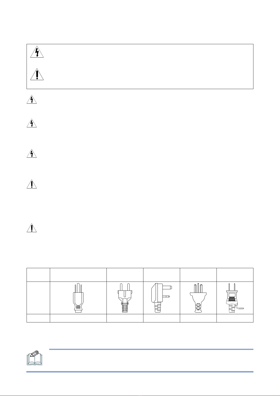
CAUTION
Please use the power cord provided with this monitor in accordance with the table below. If a
power cord is not supplied with this equipment, please contact your supplier. For all other cases,
please use a power cord that matches the AC voltage of the power outlet and has been approved
by and complies with the safety standard of your particular country.
North America
(USA/Canada/Taiwan)
European Union
UK
China
Japan
Plug Shape
Voltage
120 (110 in Taiwan)
230
230
220
100
When operating a display which requires an AC 125-240V power supply, make sure to use a power
supply cord that matches the power supply voltage of the AC power outlet being used.The power
supply cord should be connected to an outlet with a grounded connection.
NOTE: For safety information in French refer to APPENDIX E: SAFETY INFORMATION
on page 58.

6| « SAFETY INSTRUCTIONS »
NOTE: This product can only be serviced in the country where it was purchased. Use the
power cord which has BSMI mark at both ends when you use this monitor in Taiwan.
The intended primary use of this product is as an Information Technical Equipment in
an office or domestic environment.
The product is intended to be connected to an external device and is not intended
for the display of television broadcast signals.
Power Management
To reduce power the display supports various power-off methods.
The default Power Saving setting will have the display switch to standby after 60 seconds if it has no
signal input from the current signal source.
When the Detect Signal & Slot Power setting and the RS232 Switch setting are both set to Off (the
default settings), the display will switch to standby after 60 seconds if it has no signal from the
current input source.
When Detect Signal & Slot Power is set to On or RS232 Switch is set to COM Port, the display
backlight will turn off after 60 seconds if it has no signal from the current input source.
NOTE:
When the Power Saving setting is set to On the display will meet the ENERGY
STAR®energy efficiency requirements.
When the Detect Signal & Slot Power and RS232 Switch settings are both set to Off
the display will meet the ENERGY STAR®energy efficiency requirements.
Automatic Wake Up
In its default setting, if a device is connected to the display via the HDMI IN1 port and the input
source is set to HDMI1, after entering standby mode, the display will wake up automatically when a
signal from the device is detected.
When the Detect Signal & Slot Power setting is set to On or the RS232 Switch setting is set to
COM Port, if a device is connected to the display via the HDMI IN1 / HDMI IN2 / DP / Slot port,
after the display backlight turns off, the display will wake up automatically when a signal from the
device is detected.

« SAFETY INSTRUCTIONS » | 7
Recommended Use
For optimum performance, allow 20 minutes for warm-up.
Position the display at a 90° angle to windows and other light sources to minimize glare and
reflections.
Clean the display surface with a lint-free, non-abrasive cloth. Avoid using any cleaning solution
or glass cleaner.
Adjust the display’s brightness and contrast to enhance readability.
Avoid displaying fixed patterns on the monitor for long periods of time to avoid image
persistence (after image effects).
Ergonomics
To realize the maximum ergonomic benefits, the following is recommended:
Use the preset Size and Position controls with standard signals.
Use the preset Color Setting.
Use non-interlaced signals.
Do not use primary color blue on a dark background, as it is difficult to see and may produce
eye fatigue due to insufficient contrast.
Suitable for entertainment purposes at controlled luminous environments, to avoid disturbing
reflections from the screen.
Cleaning the LCD Panel
When the liquid crystal panel is dusty, please gently wipe with a soft cloth.
Do not rub the LCD panel with hard material.
Do not apply pressure to the LCD surface.
Do not use oleic acid cleaner as it will cause deterioration or discolor on the LCD surface.
Cleaning the Cabinet
Unplug the power supply.
Gently wipe the cabinet with a soft cloth.
To clean the cabinet, dampen the cloth with a neutral detergent and water, wipe the cabinet
and follow with a dry cloth.
NOTE: DO NOT clean with benzene thinner, alkaline detergent, alcoholic system
detergent, glass cleaner, wax, polish cleaner, soap powder, or insecticide. Rubber or vinyl
should not be in contact with the cabinet for an extended period of time. These types of
fluids and materials can cause the paint to deteriorate, crack or peel.

8| « SAFETY INSTRUCTIONS »
Declarations
FCC Declaration of Conformity
47 CFR § 2.1077 Compliance Information
Name of Responsible Party:
AU Optronics Corp.America
Address of Responsible Party:
37085 Grand River Ave.
Farmington, MI 48335
U. S.A.
Contact Person:
Company Representative
Phone No.:
Fax No.:
FCC Compliance Statement
This device complies with Part 15 of the FCC Rules. Operation is subject to the following two
conditions: (1) this device may not cause harmful interference, and (2) this device must accept any
interference received, including interference that may cause undesired operation.
FCC Information
This equipment has been tested and found to comply with the limits for a Class A digital device,
pursuant to Part 15 of the FCC Rules. These limits are designed to provide reasonable protection
against harmful interference when the equipment is operated in a commercial environment. This
equipment generates, uses, and can radiate radio frequency energy and, if not installed and used in
accordance with the instructions manual, may cause harmful interference to radio communications.
Operation of this equipment in a residential area is likely to cause harmful interference in which
case the user will be required to correct the interference at his own expense.
CE Declaration of Conformity
Hereby, AUO Inc., declares that this LCD monitor is in compliance with the essential requirements
and other relevant provisions of EMC Directive 2014/30/EU, Low Voltage Directive 2014/35/EU,
and RoHS Directive 2011/65/EU and Directive 2009/125/EC with regard to establishing a
framework for the setting of eco-design requirements for energy-related product.
Notice: Shielded cables
All connections to other computing devices must be made using shielded cables to maintain
compliance with EMC regulations.
Caution
Changes or modifications not expressly approved by the manufacturer could void the user
authority, which is granted by the Federal Communications Commission, to operate this product.
Notice: Canadian users
This Class A digital apparatus complies with Canadian ICES-003.
Cet appareil numérique de la classe A est conforme à la norme NMB-003 du Canada.
As an ENERGY STAR Partner, we have determined that this product meets the
ENERGY STAR guidelines for energy efficiency.

« WHAT’S IN THE BOX » | 9
WHAT’S IN THE BOX
Package Contents
Check your product box for the following items. If there are any missing accessories, contact the
local dealer where you purchased your display. The illustrations in this manual may differ from the
actual product and items.
Display
Remote Control and
AAA Batteries
Power Cord (USA/Taiwan)
Power Cord (Europe/Korea)
RS232 Cable
IR Extender
Quick Start Guide
(and Assorted Documents)
NOTE: The IR extender features an LED that indicates the power status of the display.
Green
The display is powered on.
Red
The display is in stand-by mode.
10 | « MOVING THE DISPLAY »
MOVING THE DISPLAY
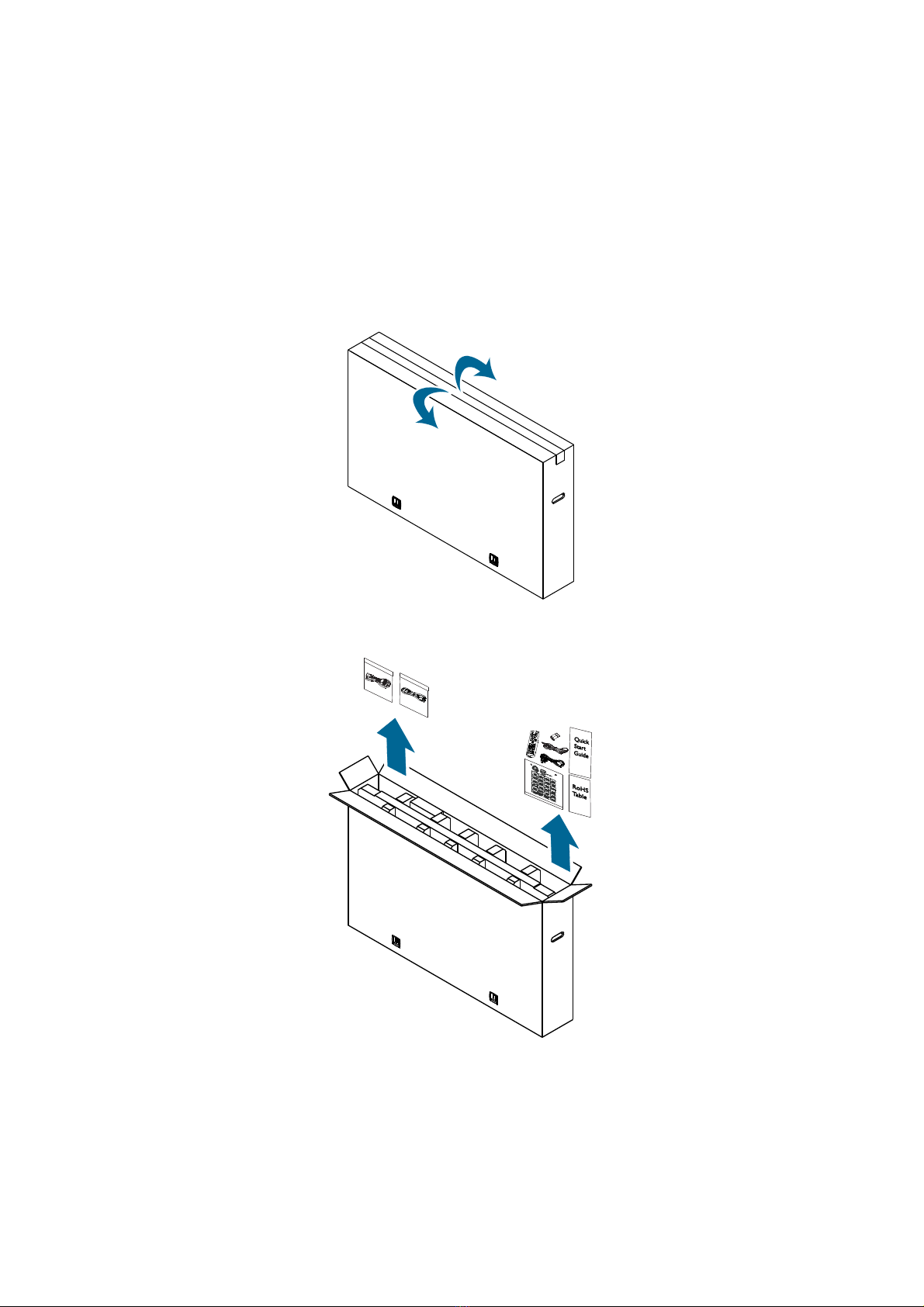
Unpacking the Display
Before unpacking the display, prepare a flat and stable surface near a wall outlet. Set the product
box in an upright position according to the arrow markings on the outside of the product box.
1. Open the product box from the top of the box.
2. Remove the accessories from the top of the EPE foam packaging cushion.
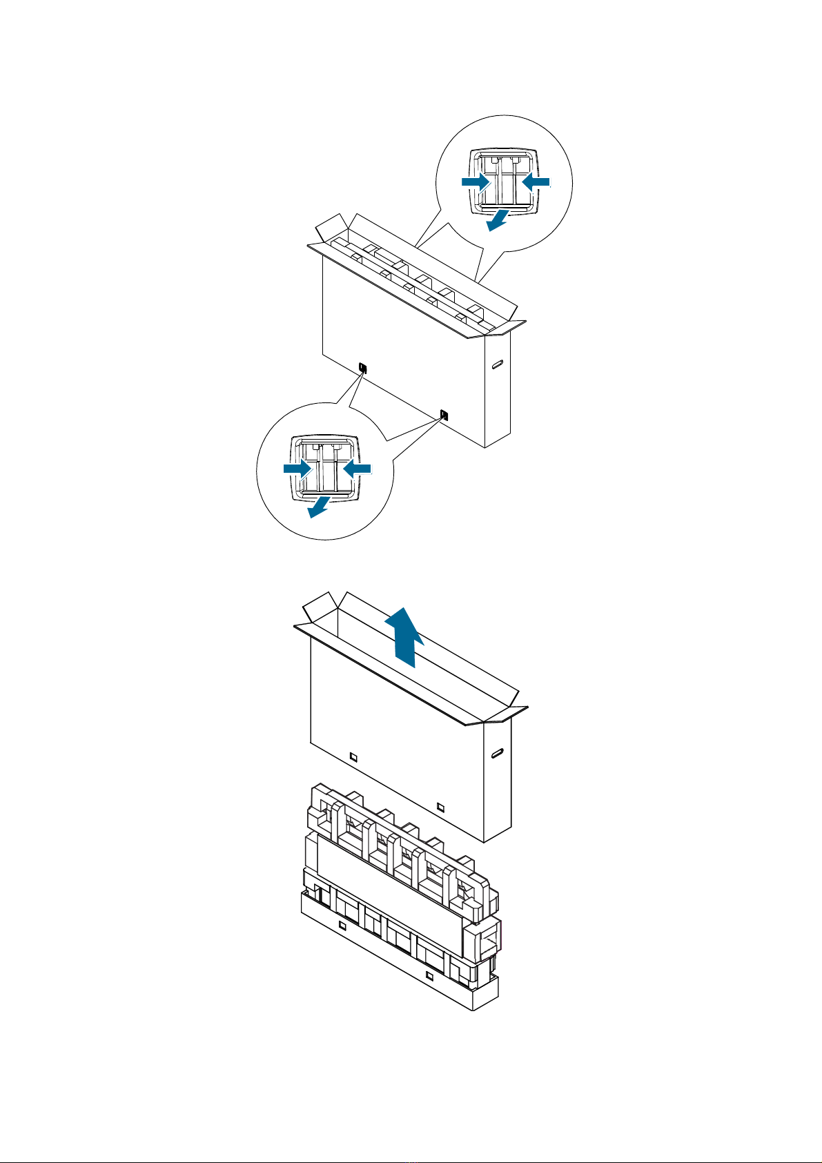
« MOVING THE DISPLAY » | 11
3. Pinch the four clip locks to the unlock position and pull to remove.
4. Remove the upper case from the top of the box.
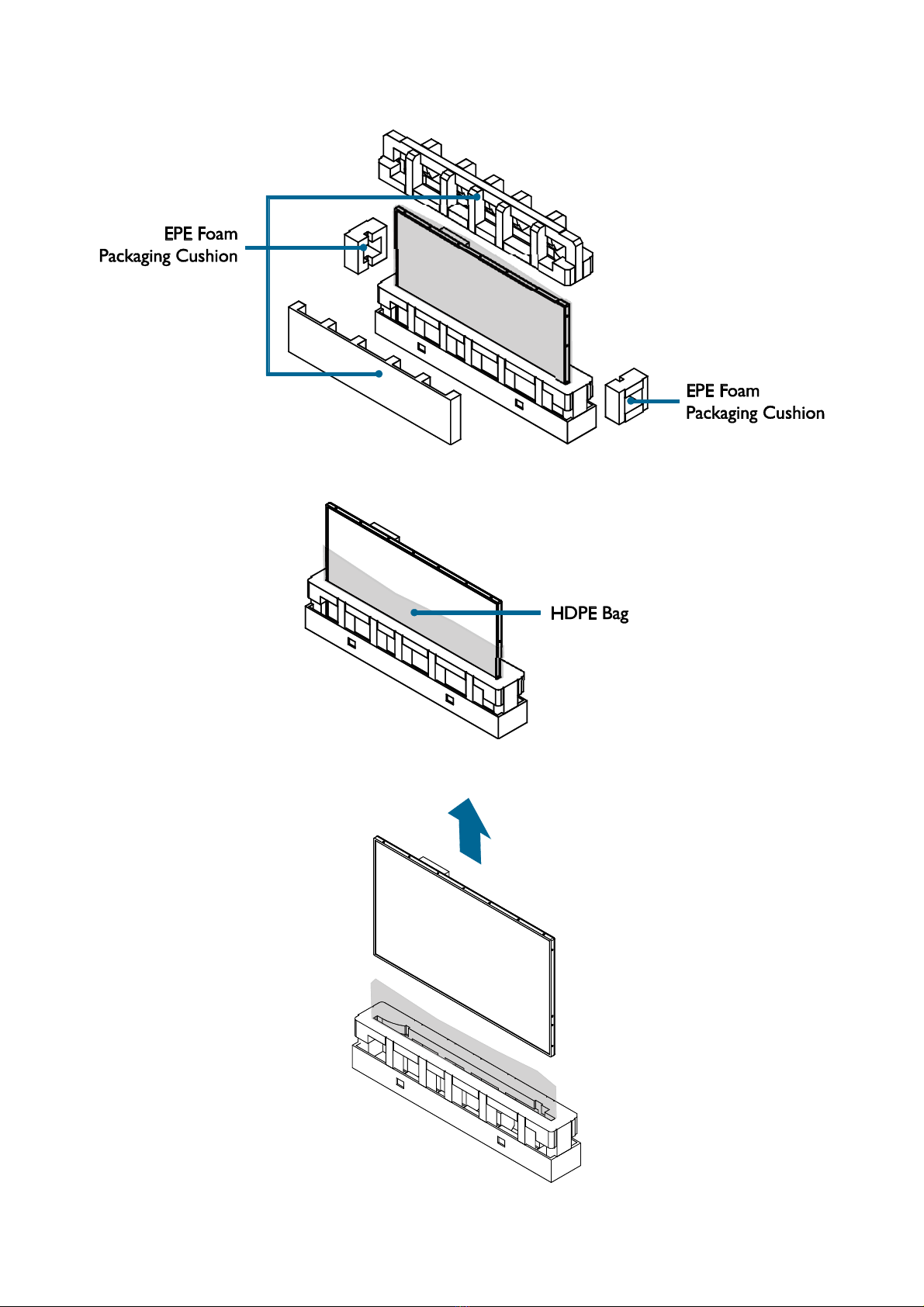
12 | « MOVING THE DISPLAY »
5. Remove the EPE foam packaging cushions.
6. Pull down the HDPE bag around the display.
7. Remove the display from the bottom case.
« MOVING THE DISPLAY » | 13
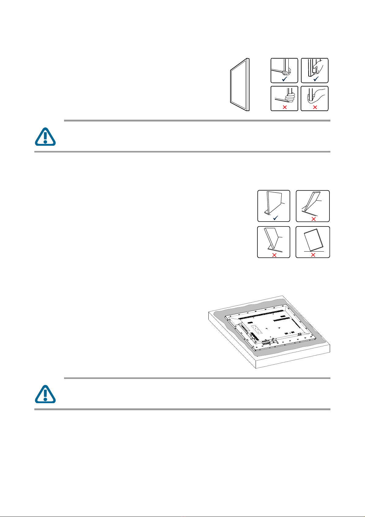
Carrying the Display
When carrying the display, always carry it using both hands
and with the LCD panel facing forward. DO NOT carry
the display while putting pressure on the screen at the
front of the chassis.
CAUTION: Avoid applying force or using sharp objects on the screen or the frame
around the screen at all times.
Placing the Display
When placing the display, always keep the display upright or keep the
screen face down as illustrated in the Setting Down the Display
section. Never tilt the display towards the left, right or balanced on a
single corner of the frame.
Setting Down the Display
When setting the display down, place the screen face
down on a flat and stable surface covered by a protective
sheet and a table cushion as shown in the illustration
provided.
CAUTION: Never press or place anything on the back cover. This may damage the
internal parts of the display.

14 | « MOUNTING THE DISPLAY »
MOUNTING THE DISPLAY
Adjusting Directions
To avoid injuries, follow the installation instructions to safely install the display onto a wall.
It is recommended to allow a certified installation company to conduct the wall mounting
operation.
CAUTION: Dropping the display may cause injuries to people around it.
NOTE: A wall mount may be purchased separately for easier installation.
If you want to use the display vertically or horizontally, adjust the display such that the main power
switch on the back of the display is pointing downward or rightward and the respective arrow on
the rear of the display is pointed upward (as illustrated below). If the display is not mounted in such
a way the display may not function properly.
Horizontal (Landscape)
Vertical (Portrait)
NOTE: Before mounting, make sure there is space to connect your devices. See
“CONNECTING THE DISPLAY” on page 27.
« MOUNTING THE DISPLAY » | 15
Wall Mount Specifications
MOUNTING LOCATION
It is important to install the display in a location that allows adequate ventilation around the display,
so that heat can properly dissipate away from the display and its mounting accessories. If installing
the display onto a ceiling or wall with a mounting bracket, then the ceiling and wall must be strong
enough to support the display and its mounting accessories.
Ventilation Requirements
When mounting in an enclosed space or recessed area, leave adequate room between the display
and the enclosure in order to allow heat to disperse, as shown below.
Make sure to provide air conditioning around the display or adequate ventilation, so that heat can
properly dissipate away from the unit and mounting accessories.
Please note the following:
DO NOT install in locations where a door can knock against the display.
DO NOT install in areas where the display will be subjected to dust and/or strong vibrations.
DO NOT install the display next to the location where the main power supply enters the
building.
DO NOT install the display in an area where people can easily grab and hang onto the display
or its mounting accessories.
16 | « MOUNTING THE DISPLAY »
MOUNTING EQUIPMENT
CAUTION: This display cannot be used or installed without a support stand or a
mounting support accessory.
The display is designed for use with the VESA mounting system. When using mounting accessories
other than those that are approved by the dealer, they must comply with the VESA compatible
(FDMlv1) mounting method. It is recommended to use mounting interfaces that comply with
UL1678 standard in North America.
WALL MOUNTING
For proper installation it is strongly recommended to use a trained, qualified technician.
The back of the display is equipped with four screw-holes with dimensions of VESA mount 400 x
400mm (for 55”/75”) or VESA mount 400 x 600mm (for 65”). Firmly secure a wall mount onto the
display. Use four M6 screws on the 55”displays (maximum length: 20mm, maximum torque:
18 kgf-cm), four M8 screws on the 65”displays (maximum length: 20mm, maximum torque:
20 kgf-cm), and four M6 screws on the 75”displays (maximum length: 10mm, maximum torque:
18 kgf-cm).
NOTE: Refer to the proper installation instructions included with the mounting
equipment.
1. Place the display face-down on a flat, padded surface for safe installation of mounting
accessories.
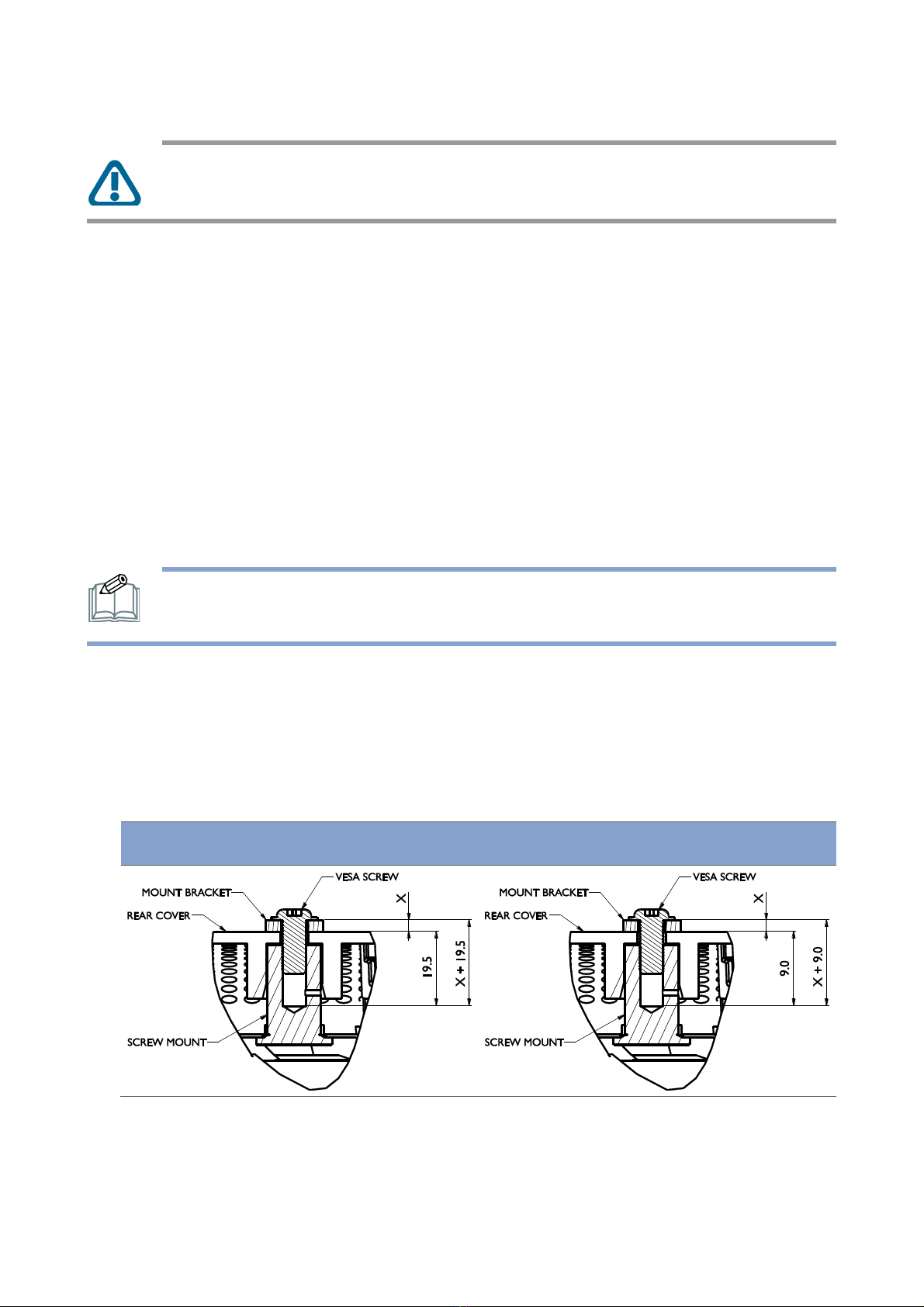
2. For installation, it is recommended to use M6/M8 screws and tighten them securely. Screws
should have a Boss screw thread of at least 15mm (for 55”/65”) or 8mm (for 75”), a
loose-proof spring washer, and a length of 10mm (for 55”/65”) or 6mm (for 75”) longer than
the thickness of the mounting bracket.
55”/65”
75”
(Recommended Torque: <18 kgf.cm). Bracket hole should be under φ8.5mm.

« MOUNTING THE DISPLAY » | 17
55”
65”
75”

18 | « MOUNTING THE DISPLAY »
3. Make sure there is no gap between the display and the bracket.
4. To ensure safe installation, use two or more brackets to mount the display. Mount the display
to at least two points on the installation location.
NOTE:
Be careful to avoid tipping the display over when attaching accessories.
Periodically check for loose screws, gaps, distortions, or other problems that may
occur with the mounting apparatus. If a problem is detected, please refer to qualified
personnel for service.
Regularly check the mounting location for signs of damage or weakness that may
occur over time.
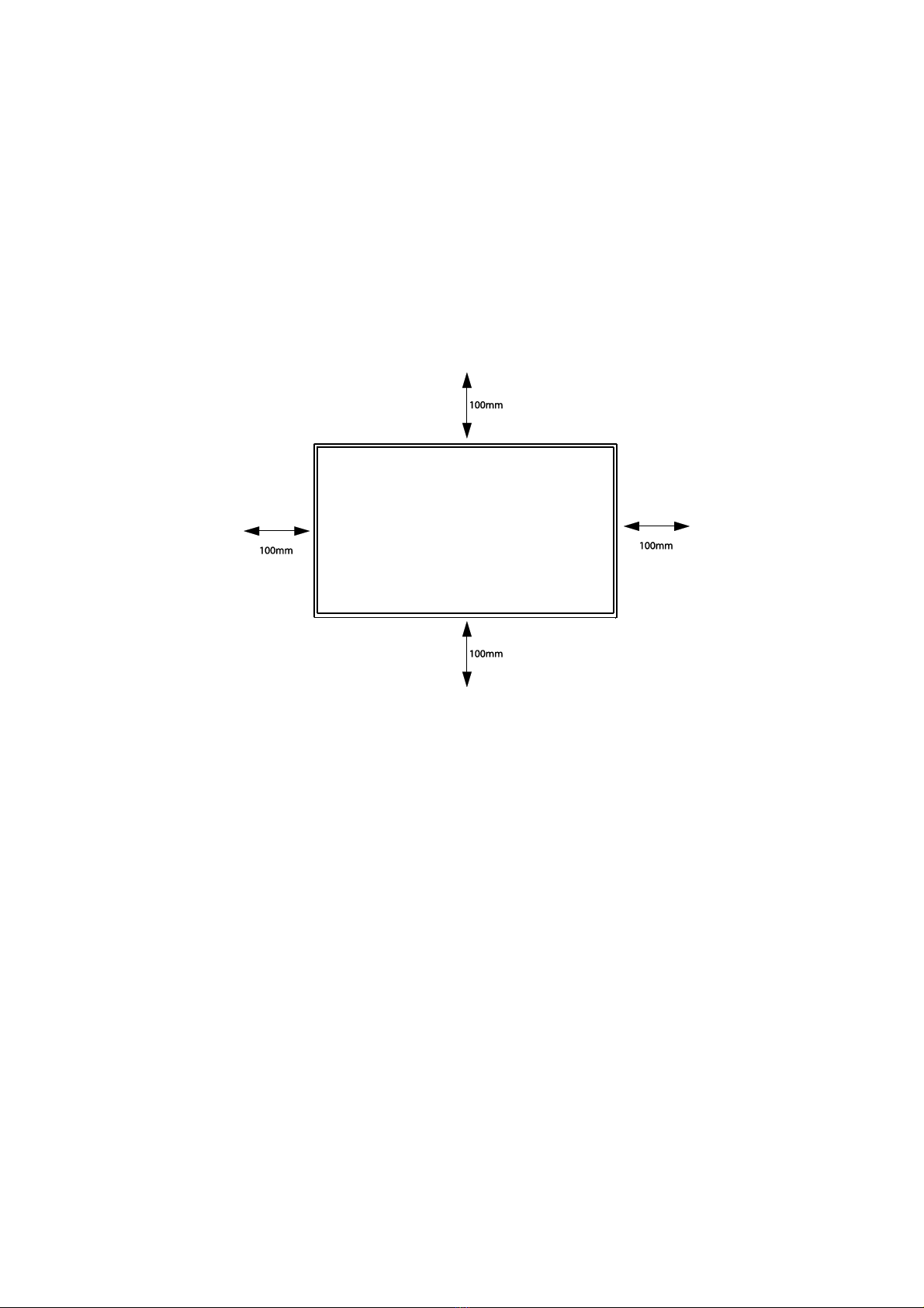
Flat Wall Installation
Installation on a Flat Wall (Minimum Distance: 40mm)
When installing the display on a wall face, there has to be at least 40mm of
space between the display and the wall for ventilation purposes.
The display must be installed in an environment with proper ventilation to
prevent it from overheating. Do not block the ventilation holes on the top,
left, and right sides while keeping the display away from any heat source.
NOTE:
To prevent glare when used in a location with strong sunlight, it is recommended to
add a cover over the display.
For mounting information in French refer to APPENDICE F:
MONTAGE DE L'AFFICHAGE on page 61.
40mm

« MOUNTING THE DISPLAY » | 19
Protection from Overheating
When the display is close to overheating a warning code will show up at the top-right corner of the
screen and the display will automatically behave in the following way:
Warning Code Displayed on Screen
H1
H2
Ambient
Temperature
≥ 43°C
≥ 45°C
Internal
Temperature
(OSD On)
55”
≥ 65°C
55”
≥ 67°C
65”
≥ 72°C
65”
≥ 74°C
75”
≥57°C
75”
≥ 59°C
Behavior/
Adjustment
The BLU brightness will decrease
to a level of about 70%.
The BLU brightness will decrease
to a level of about 10%.
Under these circumstances the user must check and ensure that there is enough space around the
display for heat dissipation.
NOTE: The threshold to trigger an ambient temperature warning code varies slightly
depending on the way the display is set up. For example, for a display with multiple ports
in use, the threshold is 43°C while for a display with only one port in use the threshold
might be higher than 43°C.
Only when the ambient temperature lowers to below 35°C will the BLU brightness return to
100%.
BLU Recovery
Ambient
Temperature
≤ 35°C
Internal
Temperature
(OSD On)
55”
≤ 63°C
65”
≤ 66°C
75”
≤49°C

20 | « SETTING UP THE DISPLAY »
SETTING UP THE DISPLAY
Main Components
The following images and tables show the location of the connectors and other components.
55”/65”
Item
Description
1
Speakers
Emit audio from the display.
2
Air Vents
Disperses heat from the display.
3
Control Buttons
See “Control Buttons” on page 24 for detailed information.
4
SDM-L
Slot used to install a large Intel® Smart Display Module (SDM Large).
For more details see “Installing an SDM Module” on page 31.
5
SDM-S
Slot used to install a small Intel® Smart Display Module (SDM Small).
For more details see “Installing an SDM Module” on page 31.
6
USB
Connects with a flash drive to display digital media or update the
display’s firmware.
NOTE: Use a flash drive with a maximum storage capacity
of 512 GB for FAT32 /NTFS formats.
7
DP IN
Connects with devices transmitting audio/video using the DP
(DisplayPort) interface.
8
HDMI IN1
Connects with devices transmitting audio/video using the HDMI
interface.
9
HDMI IN2
Connects with devices transmitting audio/video using the HDMI
interface.
This manual suits for next models
5
Table of contents
Other SDM Watch manuals


