Seiko S141A Installer manual

- 1 -
PARTS CATALOGUE /TECHNICAL GUIDE
Cal. S141A, S143A
Cal. No.
Item S141A
(x 0.7)The illustrations refer to Cal. S143A.
Module
Module size Outside diameter 49.3 mm between 6 o’clock and 12 o’clock sides
43.0 mm between 3 o’clock and 9 o’clock sides
[SPECIFICATIONS]
S143A
–Casing diameter
Height 8.75 mm
Display medium Nematic Liquid Crystal, FEM (Field Effect Mode)
Liquid crystal driving system 1/4 multiplex driving system
Display system • Stopwatch display (Up to 10 hours)
•Split time/lap time measurement
•Total time measurement/lap time measurement in progress
• Time/calendar display
• Stroke display (Only for Cal. S141A)
Additional mechanism • Memory function: Up to 300 measurements
• Memory capacity indicator
• Confirmation sound for watch operation
• Contrast adjustment function
• Battery life indicator
• Printout function (Only for Cal. S143A)
Regulation system Nil
Measuring gate by quartz tester Any gate can be used.
Battery SEIKO CR2430, Sony CR2430
Battery life is approximately 3 years.
(When the stopwatch is used for 3 hours a day or less)
Voltage: 3.0 V
±0.0006% at normal temperature range (corresponds to a loss/gain
(monthly rate) of less than 15 seconds)
Loss/gain

- 2 -
PARTS CATALOGUE Cal. S141A, S143A
Disassembling procedures Figs. : 1 →17
Reassembling procedures Figs. : 17 →1
Lubricating: Types of oil Oil quantity
SEIKO Watch Oil S-6 Normal quantity
Silicone oil 500,000
➡Please see the remarks on the following pages.
(Lubricating of some parts is shown in “III. REMARKS ON DISASSEMBLING AND REASSEMBLING”)
1 Case back screw
2 Case back
Piezoelectric element
3 Case back
gasket
4 Module
5 7504 620
Jack
(only for Cal. S143A)
Jack nut
(only for Cal. S143A)
Button B
Button C
Button A
Button D
Button spring clip
Button spring
7 0022 922
Circuit block
cover screw
6 Battery
(See the
front page.)
8 4457 974
(for Cal. S141A)
4457 754
(for Cal. S143A)
Circuit block
cover
9 4246 825
Buzzer lead
terminal
10 0353 503
Spring for
switch
conductivity
11 4410 779
Circuit block
case
12 4450 851
Switch lever
13 4000 603
(for Cal. S141A)
4000 872
(for Cal. S143A)
Circuit block
14 4313 825
Connector
15 Liquid crystal
panel
16 4313 826
Switch connector
17 4512 850
Liquid crystal
panel frame

- 3 -
Remarks:
PARTS CATALOGUE Cal. S141A, S143A
TECHNICAL GUIDE
•The explanation here is only for the particular points of Cal. S140A and S143A.
•For repairing, checking and measuring procedures, refer to the “TECHNICAL GUIDE, GENERAL
INSTRUCTIONS”.
I. STRUCTURE OF THE CIRCUIT BLOCK
II. REMARKS ON BATTERY REPLACEMENT
Cal. S141A, S143A
15 Liquid crystal panel
The type of liquid crystal panel is determined based on the design of cases. Check the case number and
refer to the “SEIKO WATCH SERVICE SITE Parts Catalogue” to choose a corresponding liquid crystal
panel.
Cal. S141A Cal. S143A
C-MOS-LSI Input terminal (+)
Input terminal (–)Crystal unit
C-MOS-LSI Input terminal (+)
Input terminal (–)
Jack lead terminal
•Remarks on installing the battery
· Keep the battery level while installing it lest it should
touch the circuit block cover.
· Be careful not to short-circuit the battery connection (–)
and the circuit block cover. If this occurs, the display may
remain blank after the battery is installed.
* If the display remains blank, wait until the battery voltage
returns to the normal level. The normal display will
return.
Example of short circuit
4520 582 (S141)
4520 504 (S143)

- 4 -
TECHNICAL GUIDE Cal. S141A, S143A
•Remarks after installing the battery
After the battery is replaced with a new one, or after
the battery is re-installed following the repairing
procedures, be sure to short-circuit the AC terminal
of the circuit block and the circuit block cover with
conductive tweezers for more than 2 seconds as
illustrated at right to reset the circuit.
▼
III. REMARKS ON DISASSEMBLING AND REASSEMBLING
Use the universal movement holder for disassembling and reassembling.
4 Module (Only for Cal. S143A)
•How to remove
Unsolder them with a soldering iron, soak up the
melted solder completely with a solder wick or the
like, and then, remove the jack lead terminal.
•How to install
Set the jack lead terminal to the jack pin, taking care
not to set it upside down. Then, re-solder them with
the soldering iron.
The jack and the jack lead terminal are soldered together.
Note: When using the soldering iron, take utmost care not to deform or damage the case and other
parts by the heat of the soldering iron.
Case
Liquid crystal panel
Jack lead terminal
Soldered portion
5 Jack
The jack is only available for supply with the nut.
•How to install
To reassemble the jack, set the notch of the jack to the groove of the case.
9 Buzzer lead terminal
•How to remove
Remove the buzzer lead terminal after detaching the circuit block case from
the circuit block.
•How to install
To install the buzzer lead terminal, set the end portion of the buzzer lead
terminal to the groove of the circuit block case, and then, turn the buzzer lead
terminal slightly so that it does not come off.

- 5 -
TECHNICAL GUIDE Cal. S141A, S143A
12 Switch lever
•Setting position and lubricating
Lubricate the switch levers as shown in the illustrations below and set them on the rear of the circuit
block case.
a
Ab
d
A
e
f
c
B
B
Set the switch lever so that the portions
from “a” to “f” are positioned under
the collar of the circuit block.
[ Lubrication ]
“A” portion
“B” portion
15 Liquid crystal panel
16 Switch connector
•How to install
Set the liquid crystal panel and switch connector as
shown in the illustration at right.
Set the stopper of the liquid crystal panel to
the groove of the liquid crystal panel frame.
Set the switch connector with the conductive
portion (black) up.
IV. VALUE CHECKING
•Current consumption
For the whole module : Less than 12 µA (with voltage of 3.0 V supplied from a battery)
For the circuit block alone : Less than 10 µA (with voltage of 3.0 V supplied from a battery)
How to measure the current consumption
While applying the probe of the tester as shown in the illustrations below, reset the circuit with conductive
tweezers for more than 2 seconds. Then, measure the current consumption.
For the whole module For the circuit block alone
Tweezers

- 6 -
TECHNICAL GUIDE Cal. S141A, S143A
•All the segments lit up
1. Press the mode button (button “D”) to show the TIME/CALENDAR mode.
2. Press button “B” to show the TIME/CALENDAR SETTING display.
3. Press buttons “A” and “B” at the same time. All the segments of the display will light up.
4. Check if the displays below appear for the respective watches.
Cal. S141A Cal. S143A
* If the stopwatch is left untouched with all the segments lit up, it will automatically return to the TIME/
CALENDAR mode in 1 to 2 minutes. To return to the TIME/CALENDAR mode manually, press button “D”.
* To measure the time accuracy with the quartz tester, light up all the segments of the display.
Button B Button A
Button D
Button B Button A
Button D
•Connection with the System Printer SP12 (Only for Cal. S143A)
How to connect
* In inserting the plug of the connecting
cord into the jack, check that their
notched portions properly meet with
each other.
Notch
Stopwatch
Cal. S143A System Printer
SP12
Connecting Cord SC-11
A
B
C
D
Jack
Power switch
Print mode
selection switch
Jack

- 7 -
TECHNICAL GUIDE Cal. S141A, S143A
Switch operation of the System Printer SP12
Print mode selection switch : Split time and lap time are printed out while the switch is set at “LAP.
SPLIT”.
Power switch : The switch turns on and off the printer. (When the switch is set to “ON”,
the roll paper will be advanced by one line.)
•Checking the operation of the Stopwatch Cal. S143A and the System Printer SP12
Printout during the measurement
Printout of the stored data
5. Press button “B” repeatedly. With each press of the button, the split/lap number, split time and lap
time will be printed out.
Printout of the elapsed time
1. In the STOPWATCH mode, press button “B” to reset the digits to “00”.
2. Press button “D” to show the TIME/CALENDAR mode.
3.
Press button “A” to start the measurement. The year, month, date and starting time will be printed out.
4. With each press of button “B”, the time and number of measurements are printed out.
* The elapsed time cannot be printed out by pressing button “C”.
* If the digits have not been reset to “00”, the time cannot be printed out.
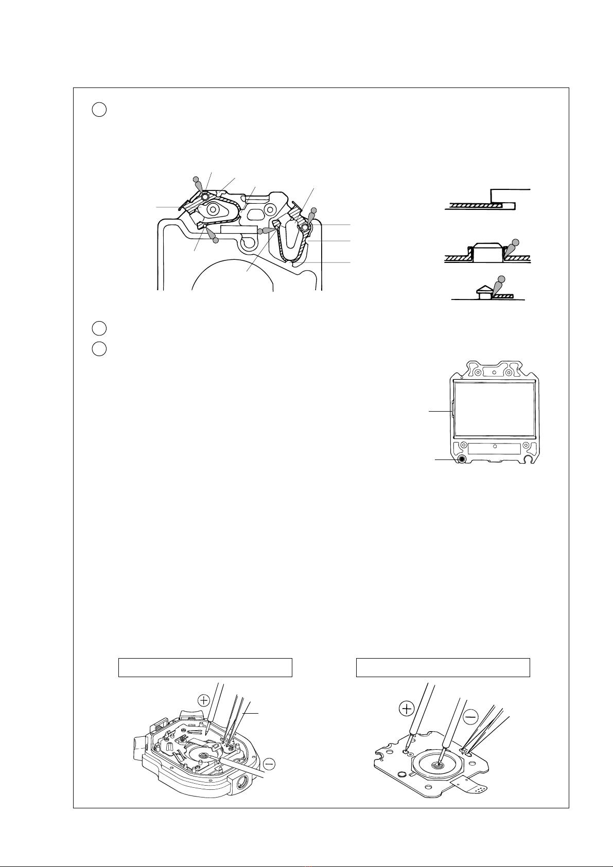
If the measurement data are not printed out properly, check the following points for the cause of failure.
1. Check if the connecting cord (SC-11) is broken, by using the tester.
2. If the batteries of the printer have run down, replace them with new ones.
3. Check if the soldered portion of the jack lead terminal of the stopwatch is damaged to cause short
circuit.
* If the printer will not operate properly after correcting the above conditions, take both the printer and
the stopwatch to a SEIKO SERVICE CENTER for repair.
* Please be informed that the repairs of the System Printer SP12 will be made only at the SEIKO
factory.
1. Turn on the power switch of the printer.
2. Slide the print mode selection switch of the printer to “LAP. SPLIT”.
3. Press button “D” to show the STOPWATCH mode.
4. Press button “A” to start the measurement. The block number, for example, “BLOCK : 1” will be
printed out.
* If the stopwatch is counting, press button “A” to stop the measurement, press button “B” to reset
the digits to “00”, and then press button “A” again to start the measurement.
* Measure the split and lap times without connecting the stopwatch and the printer.
1. Press button “A” to start the measurement.
2. Press button “B” repeatedly to measure split and lap times.
3. Press button “A” to stop the measurement.
4. Connect the stopwatch with the printer, turn on the power switch of the printer, and then, slide the print
mode selection switch of the printer to “LAP. SPLIT”.
5. Press and hold button “C” for 2 to 3 seconds. “PRINT ALL” will be displayed.
6. Release button “C”. All the stored data will automatically be displayed and then printed out
successively.

- 8 -
BUTTONS AND DISPLAYS Cal. S141A
Cal. S141A
[TIME/CALENDAR mode]
Button B (SELECT)
Selection of the digits to be adjusted
Identification number
Button D (CHANGEOVER OF MODES)
With each press of the button, the mode
changes over in the following order.
TOTAL TIME display of
the STOPWATCH mode
LAP TIME IN PROGRESS display
of the STOPWATCH mode
STROKE mode
TIME/CALENDAR mode
➧
Year
Month and date
Time
It is displayed in the 24-hour indication.
TIME/CALENDAR mode indicator
Button A (SET)
Setting the digits to be adjusted
Button C (CONTRAST)
Activation/deactivation of the contrast adjustment function
➧➧➧
[STROKE mode]
Button B (RESET)
Button D (CHANGEOVER OF MODES)
Button A (START/STOP)
Restart and stop of the stroke measure-
ment is repeated by pressing the button.
Button C (MEMORY RECALL)
STROKE mode indicator
Memory number Number of stokes per minute
Button B (LAP/SPLIT, RESET)
With each press of the button after the
measurement is started, split time and
lap time are measured.
By pressing the button to end the
measurement, the new block number
for the next measurement is displayed.
Memory capacity indicator
Indication of the available memory
STOPWATCH mode indicator
Split/lap number
Split time
(Hour, minutes, seconds and 1/100 seconds)
Button A (START/STOP)
Restart and stop of the stopwatch can be
repeated by pressing the button.
Button C (MEMORY RECALL)
Lap time
(Hour, minutes, seconds and 1/100 seconds)
Total time
(Hour, minutes, seconds and 1/100 seconds)
Button D (CHANGEOVER OF MODES)
[STOPWATCH mode]
Block mark
The block mark on the display: the block
memory mode
No block mark on the display: the single
memory mode (in any display mode)
The illustration shows the block mark
appearing on the display.

- 9 -
BUTTONS AND DISPLAYS Cal. S143A
Cal. S143A
[TIME/CALENDAR mode]
Button B (SELECT)
Selection of the digits to be adjusted
Identification number
Button D (CHANGEOVER OF MODES)
With each press of the button, the mode
changes over in the following order.
TOTAL TIME display of
the STOPWATCH mode
LAP TIME IN PROGRESS display
of the STOPWATCH mode
TIME/CALENDAR mode
Year
Month and date
Time
It is displayed in the 24-hour indication.
TIME/CALENDAR mode indicator
Button A (SET)
Setting the digits to be adjusted
Button C (CONTRAST)
Activation/deactivation of the contrast adjustment function
➧➧
Button B (LAP/SPLIT, RESET)
With each press of the button after the
measurement is started, split time and
lap time are measured.
By pressing the button to end the
measurement, the new block number
for the next measurement is displayed.
Memory capacity indicator
Indication of the available memory
STOPWATCH mode indicator
Split/lap number
Split time
(Hour, minutes, seconds and 1/100 seconds)
Button A (START/STOP)
Restart and stop of the stopwatch can be
repeated by pressing the button.
Button C (MEMORY RECALL)
Lap time
(Hour, minutes, seconds and 1/100 seconds)
Total time
(Hour, minutes, seconds and 1/100 seconds)
Button D (CHANGEOVER OF MODES)
[STOPWATCH mode]
➧
2006-9
This manual suits for next models
1
Table of contents
Other Seiko Watch manuals

Seiko
Seiko V195A Quick start guide

Seiko
Seiko Astron 8X53 Assembly instructions

Seiko
Seiko Cal. 8L35 User manual

Seiko
Seiko S810 User manual

Seiko
Seiko SDWE21P1 User manual

Seiko
Seiko 6L35 User manual

Seiko
Seiko ANALOGUE QUARTZ SOLAR V145 User manual

Seiko
Seiko Cal. 7T12 User manual

Seiko
Seiko 2A27 User manual

Seiko
Seiko Cal. 4R15 User manual

Seiko
Seiko 7D Series Owner's manual

Seiko
Seiko Astron SSJ009J User manual

Seiko
Seiko AUTO CALENDAR J User manual

Seiko
Seiko 8V36 User manual

Seiko
Seiko S034 User manual

Seiko
Seiko 6M15 User manual

Seiko
Seiko 5D44 User manual

Seiko
Seiko Conceptual SWR073P User manual

Seiko
Seiko 5T82 User manual

Seiko
Seiko 7K52 User manual