Sea-Bird Electronics SBE 38 User manual
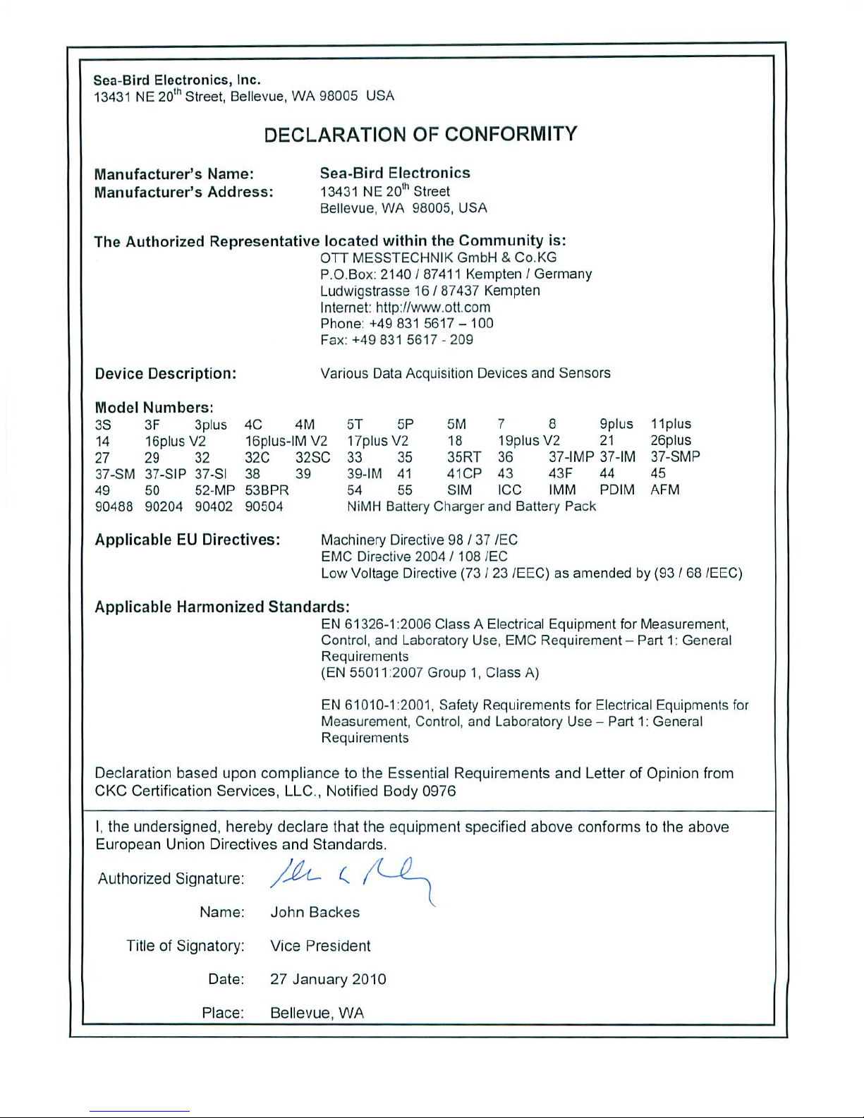
Sea-Bird Electronics, Inc.
13431 NE 20th Street
Bellevue, Washington 98005 USA
Tel: 425/643-9866
Fax:425/643-9954
SBE 38
Digital Thermometer
User Manual, Version 013

This page intentionally left blank.

SEA-BIRD ELECTRONICS, INC.
13431 NE 20th St.
Bellevue, Washington 98005 USA
Phone: (425) 643 9866
Fax: (425) 643 9954
Email: [email protected]
SBE 38 DIGITAL THERMOMETER OPERATING MANUAL
TABLE OF CONTENTS
Manual Generation Date....................................................................................................................................................................................................................................
1
Limited Liability Statement...............................................................................................................................................................................................................................
2
Declaration of Conformity.................................................................................................................................................................................................................................
4
SBE 38 Manual - Version 013...............................................................................................................................................................................................................................
5
SBE 38 Reference Sheet - Version 004......................................................................................................................................................................................................................
38
Calibration Certificates..................................................................................................................................................................................................................................
40
SBE 38 Specification Sheet................................................................................................................................................................................................................................
45
Appnote 42ITS-90 Temperature Scale.......................................................................................................................................................................................................................
47
Appnote 56Interfacing to RS-485 Sensors..................................................................................................................................................................................................................
48
Appnote 57Connector Care.................................................................................................................................................................................................................................
50
Appnote 68USB Ports......................................................................................................................................................................................................................................
53
Appnote 71Desiccant Use and Regeneration.................................................................................................................................................................................................................
54
Dwg 32277ACable Assy, RMG-4FS to DB-9S with Power Leads..................................................................................................................................................................................................
60
dwg 32604B Cable Assy, RMG-4FS to DB-9S with 9V Connector...............................................................................................................................................................................................
61
Warranty..................................................................................................................................................................................................................................................
62
Service Request Form......................................................................................................................................................................................................................................
65

Manual Generation Date: 26 August 2011
1

L I M I T E D L I A B I L I T Y S T A T E M E N T
Extreme care should be exercised when using or servicing this equipment. It should be used or
serviced only by personnel with knowledge of and training in the use and maintenance of
oceanographic electronic equipment.
SEA-BIRD ELECTRONICS, INC. disclaims all product liability risks arising from the use or servicing of
this system. SEA-BIRD ELECTRONICS, INC. has no way of controlling the use of this equipment or of
choosing the personnel to operate it, and therefore cannot take steps to comply with laws pertaining to
product liability, including laws which impose a duty to warn the user of any dangers involved in
operating this equipment. Therefore, acceptance of this system by the customer shall be conclusively
deemed to include a covenant by the customer to defend, indemnify, and hold SEA-BIRD
ELECTRONICS, INC. harmless from all product liability claims arising from the use of servicing of this
system.
2

This page intentionally left blank.
3
4

SBE 38 Digital
Oceanographic
Thermometer
With RS-232 or optional RS-485 Interface
Note: NEW ADDRESS
as of January 2010
User’s Manual
Sea-Bird Electronics, Inc.
13431 NE 20th Street
Bellevue, Washington 98005 USA
Telephone: +1 425-643-9866
Fax: +1 425-643-9954
E-mail: seabird@seabird.com Manual Version #013, 03-23-11
Website: www.seabird.com Firmware Version 1.4 and later
5

2
Limited Liability Statement
Extreme care should be exercised when using or servicing this equipment. It should be used or serviced
only by personnel with knowledge of and training in the use and maintenance of oceanographic
electronic equipment.
SEA-BIRD ELECTRONICS, INC. disclaims all product liability risks arising from the use or servicing
of this system. SEA-BIRD ELECTRONICS, INC. has no way of controlling the use of this equipment
or of choosing the personnel to operate it, and therefore cannot take steps to comply with laws
pertaining to product liability, including laws which impose a duty to warn the user of any dangers
involved in operating this equipment. Therefore, acceptance of this system by the customer shall be
conclusively deemed to include a covenant by the customer to defend, indemnify, and hold SEA-BIRD
ELECTRONICS, INC. harmless from all product liability claims arising from the use or servicing of
this system.
6

Manual revision 013 Table of Contents SBE 38
3
Table of Contents
Section 1: Introduction ....................................................................................4
About this Manual .............................................................................................4
Quick Start .........................................................................................................4
Unpacking SBE 38.............................................................................................5
Section 2: Description of SBE 38 ....................................................................6
System Description ............................................................................................6
Specifications.....................................................................................................7
Dimensions and End Cap Connector .................................................................8
Section 3: Preparing SBE 38 for Deployment ...............................................9
Installing Software .............................................................................................9
Power and Communications Test ......................................................................9
Test Setup ...................................................................................................9
Test ...........................................................................................................10
Section 4: Deploying and Operating RS-232 SBE 38..................................13
Sampling Modes ..............................................................................................13
Polled Sampling........................................................................................13
Continuous Sampling................................................................................14
Baud Rate, Cable Length, and Power ..............................................................15
Command Descriptions....................................................................................17
Data Formats....................................................................................................19
Deployment......................................................................................................19
Recovery ..........................................................................................................20
Section 5: Routine Maintenance and Calibration .......................................21
Corrosion Precautions......................................................................................21
Connector Mating and Maintenance ................................................................21
Sensor Calibration............................................................................................22
Glossary ..........................................................................................................23
Appendix I: Functional Description .............................................................24
Sensor Interface ...............................................................................................24
Settings ............................................................................................................24
Appendix II: Electronics Disassembly/Reassembly ....................................25
Appendix III: RS-485 Interface....................................................................26
Operation Description......................................................................................26
Command Descriptions....................................................................................27
RS-485 Commands...................................................................................27
All Other Commands ................................................................................28
Data Formats....................................................................................................28
Wiring ..............................................................................................................29
Conversion of RS-232 to RS-485 or RS-485 to RS-232..................................29
Appendix IV: RS-232 Command Summary ................................................30
Appendix V: Replacement Parts ..................................................................31
Appendix VI: Manual Revision History ......................................................32
Index................................................................................................................33
7

Manual revision 013 Section 1: Introduction SBE 38
4
Section 1: Introduction
This section includes a Quick Start procedure, and photos of a standard
SBE 38 shipment.
About this Manual
This manual is to be used with the SBE 38 Digital Oceanographic
Thermometer. It is organized to guide the user from installation through
operation and data collection. We’ve included detailed specifications,
command descriptions, maintenance and calibration information, and helpful
notes throughout the manual.
Sea-Bird welcomes suggestions for new features and enhancements of our
products and/or documentation. Please contact us with any comments or
Monday through Friday, 0800 to 1700 Pacific Standard Time (1600 to 0100
Universal Time) in winter and 0800 to 1700 Pacific Daylight Time (1500 to
0000 Universal Time) the rest of the year.
Quick Start
Follow these steps to get a Quick Start using the SBE 38 with a standard
RS-232 interface. The manual provides step-by-step details for performing
each task:
1. Test Power and Communications (see Section 3: Preparing SBE 38
for Deployment).
2. Deploy the SBE 38 (see Section 4: Deploying and Operating RS-232 SBE 38
for a complete description of setup, or see Appendix IV: RS-232 Command
Summary):
A. Establish setup parameters.
B. Check status (DS) and calibration coefficients (DC) to verify setup.
C. Use one of the following sequences to start sampling:
•If AutoRun=N: Send Go to start sampling continuously now, or
TS or TH to take a single sample.
•If AutoRun=Y: Apply power to start sampling
continuously now.
D. Deploy SBE 38.
For an SBE 38 with optional RS-485 interface, see Appendix III: RS-485
Interface for details.
8

Manual revision 013 Section 1: Introduction SBE 38
5
Unpacking SBE 38
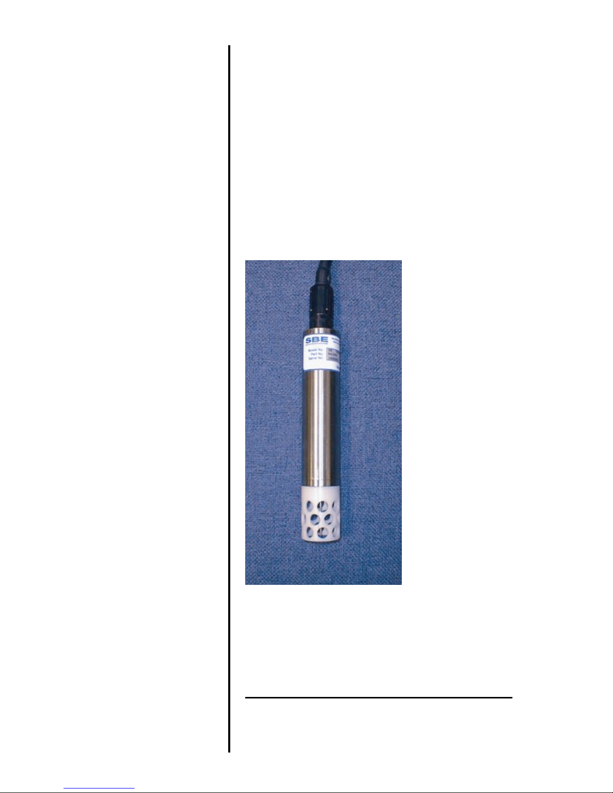
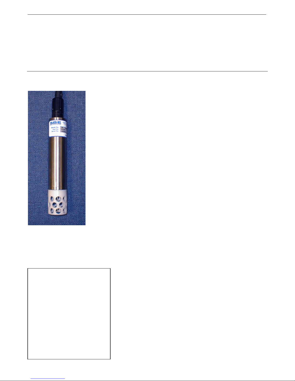
Shown below is a typical SBE 38 shipment.
Software, and Electronic Copies of
Software Manuals and User Manual
SBE 38
I/O Cable with 9V battery snap
connector and 9V battery
User Manual
SBE 38 Digital
Oceanographic
Thermometer
9
Manual revision 013 Section 2: Description of SBE 38 SBE 38
6
Section 2: Description of SBE 38
This section describes the functions and features of the SBE 38, including
specifications and dimensions.
System Description
Sophisticated A/D acquisition electronics, ultra-stable thermistor, and state-of-
the-art calibration provide the standards-level performance of an expensive
AC bridge and platinum thermometer at a small fraction of the cost. The
SBE 38 is unaffected by shock and vibration, has high accuracy and stability,
and is easy to use. It has a rugged, corrosion-proof, 10,500 meter (34,400 foot)
titanium pressure housing. Real-time temperature data is transmitted in ASCII
characters (in °C or raw counts) via an RS-232 or optional RS-485 serial
interface for display or logging by PC or data logger.
The SBE 38’s measurement range is -5 to +35 °C. Absolute accuracy is better
than 0.001 °C (1 mK) and resolution is approximately 0.00025 °C (0.25 mK).
Each sensor includes certification that demonstrates drift of less than 0.001 °C
(1 mK) during a six-month period.
Applications include calibration baths, oceanographic/aquatic research, and
environmental monitoring.
The SBE 38 operates in one of three ways:
•RS-232 (full duplex) with one SBE 38 connected to the interface
•RS-485 (half duplex) with one SBE 38 connected to the interface
•RS-485 (half duplex) with several RS-485 sensors sharing one pair
of wires
On power-up, the SBE 38 reads its EEPROM, which includes calibration
coefficients and other setup information. As programmed, the SBE 38 samples
and transmits temperature continuously, or waits for a command to begin
sampling. Note that for RS-485 applications with several sensors sharing one
pair of wires, the SBE 38 cannot sample continuously.
The SBE 38 is frequently integrated as a remote temperature sensor with one
of our thermosalinograph instruments (SBE 21 Thermosalinograph or SBE 45
MicroTSG), to provide accurate sea surface temperature. See the manuals for
those instruments for integration information.
The SBE 38 is supplied with a powerful Win 2000/XP software package,
SEASOFT V2, which includes:
•SEATERM terminal program for easy communication.
•Seasave V7 real-time data acquisition and SBE Data Processing
post-processing programs –Seasave V7 and SBE Data Processing can be
used to view and process the entire data stream, including data from the
SBE 38, when the SBE 38 is integrated with one of the following -
- SBE 21 or 45 thermosalinograph;
- SBE 16plus, 16plus V2, or 16plus-IM V2 SEACAT C-T Recorder; or
SBE 19plus V2 SEACAT CTD Profiler.
Notes:
•Help files provide detailed
information on the software.
•Separate software manuals on
CD-ROM contain detailed
information on Seasave V7 and
SBE Data Processing.
•Sea-Bird supplies the current
version of our software when you
purchase an instrument. As software
revisions occur, we post the revised
software on our FTP site. See our
website (www.seabird.com) for the
latest software version number, a
description of the software changes,
and instructions for downloading the
software from the FTP site.
10

Manual revision 013 Section 2: Description of SBE 38 SBE 38
7
Specifications
Measurement
Range -5 to +35 °C
Initial Accuracy 1±0.001 °C (1 mK)
Typical Stability 0.001 °C (1 mK) in 6 months, certified
Resolution 0.00025 °C (0.25 mK)
Calibration -1 to +32 °C
Response Time 2500 milliseconds
Self-Heating
Error less than 200 µK
RMS Noise
(at temperature
equivalent of 8.5 °C)
NAvg Noise (
°
C)
1 0.000673
2 0.000408
4 0.000191
8 0.000133
16 0.000081
32 0.000052
Note:
NAvg = number of A/D cycles per sample.
Interval between samples (seconds)
= (0.133 * NAvg) + 0.339
External Power
RS-232 (standard):
8 – 15 VDC at 15 milliamps average
RS-485 half-duplex (optional):
8 – 15 VDC at 10 milliamps average
Materials Titanium pressure case rated at
10,500 meters (34,400 feet)
Weight In water: 0.5 kg (1.2 lbs)
In air: 0.9 kg (2.0 lbs)
Notes:
1NIST-traceable calibration applying over the entire range.
2Time to reach 63% of final value following a step change in temperature.
Note:
If the SBE 38 is sampling data
and the voltage is less than
6.5 volts for 10 consecutive
scans, the SBE 38 halts sampling
and displays a low battery
indication in the data.
11

Manual revision 013 Section 2: Description of SBE 38 SBE 38
8
Dimensions and End Cap Connector
The SBE 38 is available with a 4-pin XSG-4-BCL-HP-SS or optional
MCBH-4MP (WB), TI (3/8” length base, ½-20 thread) (wet-pluggable)
external connector.
Pin Signal
1 Common
2 RS-232 Receive or RS-485 A
3 RS-232 Transmit or RS-485 B
4 Power
12
Manual revision 013 Section 3: Preparing SBE 38 for Deployment SBE 38
9
Section 3:
Preparing SBE 38 for Deployment
This section describes the software installation and the pre-check procedure
for preparing the SBE 38 for deployment.
Installing Software
Sea-Bird recommends the following minimum system requirements for
installing the software: Windows 2000 or later, 500 MHz processor,
256 MB RAM, and 90 MB free disk space for installation. Although
SEASOFT V2 was designed to work with a PC running Win 2000/XP;
extensive testing has not shown any compatibility problems when using the
software with a PC running Windows Vista or Windows 7 (32-bit).
If not already installed, install Sea-Bird software programs on your computer
using the supplied software CD:
1. Insert the CD in your CD drive.
2. Install software: Double click on SeasoftV2_date.exe (date is the date that
version of the software was created). Follow the dialog box directions to
install the software. The installation program allows you to install the
desired components. Install all the components, or just install SEATERM,
Seasave V7, and SBE Data Processing .
The default location for the software is c:\Program Files\Sea-Bird. Within that
folder is a sub-directory for each program.
Power and Communications Test
Test Setup
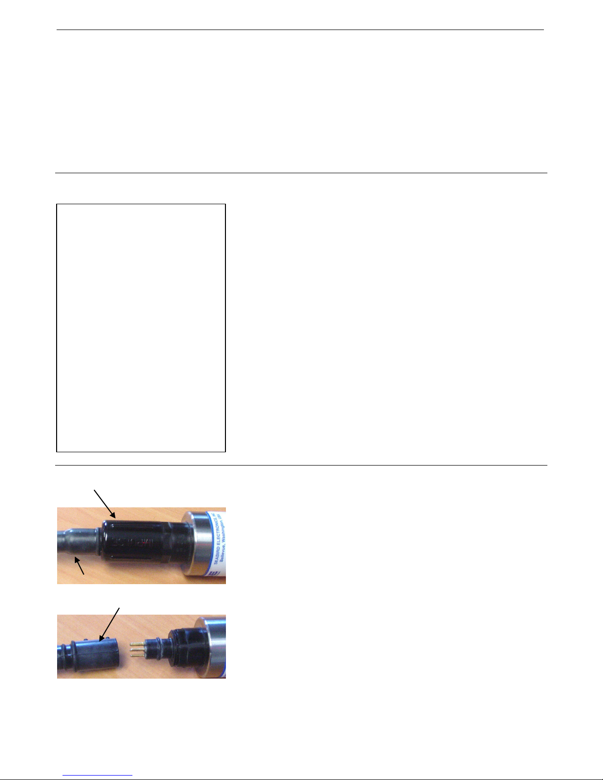
1. If applicable, remove locking sleeve and dummy plug from bulkhead
connector:
A. By hand, unscrew the locking sleeve from the SBE 38’s bulkhead
connector. If you must use a wrench or pliers, be careful not to
loosen the bulkhead connector instead of the locking sleeve.
B. Remove the dummy plug from the SBE 38’s bulkhead connector by
pulling the plug firmly away from the connector.
2. Install the Sea-Bird I/O cable on the SBE 38:
•XSG Connector (shown in photos) - Align the raised bump on the
side of the connector with the large pin (pin 1 - ground) on the
SBE 38.
•MCBH Connector (optional) – Align the pins.
3. Connect the I/O cable connector to your computer’s serial port.
4. Connect the I/O cable battery terminal clip to a 9-volt battery. Note that
the 9-volt battery supplied with the SBE 38 will provide approximately
50 hours of operation.
Cable
Locking
sleeve
Dummy plug
Notes:
•Help files provide detailed
information on the software.
Separate software manuals on the
CD-ROM contain detailed
information on Seasave V7 and
SBE Data Processing.
•It is possible to use the SBE 38
without the SEATERM terminal
program by sending direct
commands from a dumb terminal or
terminal emulator, such as Windows
HyperTerminal.
•Sea-Bird supplies the current
version of our software when you
purchase an instrument. As software
revisions occur, we post the revised
software on our FTP site. See our
website (www.seabird.com) for the
latest software version number, a
description of the software changes,
and instructions for downloading the
software from the FTP site.
13
Manual revision 013 Section 3: Preparing SBE 38 for Deployment SBE 38
10
Test
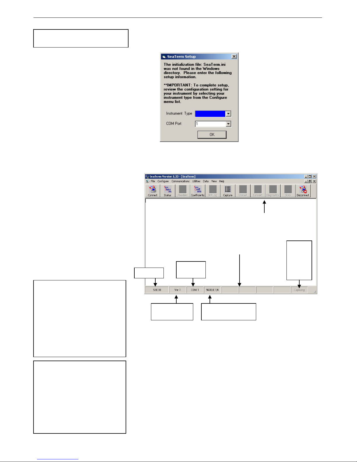
1. Double click on SeaTerm.exe. If this is the first time the program is used,
the setup dialog box may appear:
Select the instrument type (SBE 38) and the computer COM port for
communication with the SBE 38. Click OK.
2. The main screen looks like this:
•Menus – Contains tasks and frequently executed instrument
commands.
•Toolbar – Contains buttons for frequently executed tasks and
instrument commands. All tasks and commands accessed through the
Toolbar are also available in the Menus. To display or hide the
Toolbar, select View Toolbar in the View menu. Grayed out Toolbar
buttons are not applicable.
•Command/Data Echo Area – Echoes a command executed using a
Menu or Toolbar button, as well as the instrument’s response.
Additionally, a command can be manually typed in this area, from the
available commands for the instrument. Note that the instrument must
be awake for it to respond to a command (use Connect on the Toolbar
to wake up the instrument).
•Status bar – Provides status information. To display or hide the Status
bar, select View Status bar in the View menu.
Note:
See SEATERM’s help files.
Note:
There is at least one way, and as
many as three ways, to enter
a command:
•Manually type a command in
Command/Data Echo Area
•Use a menu to automatically
generate a command
•Use a Toolbar button to
automatically generate
a command
Note:
Once the system is configured and
connected (Steps 3 through 5
below), to update the Status bar:
•on the Toolbar, click Status; or
•from the Utilities menu, select
Instrument Status.
SEATERM sends the status
command, which displays in the
Command/Data Echo Area, and
updates the Status bar.
Status bar
Menus
Command/Data Echo Area
Toolbar
Instrument
Computer
COM port
Instrument
EPROM version
Baud rate, data bits,
stop bits, and parity
Capture
to file
status –
grayed
out if not
capturing
SBE 38
14
Manual revision 013 Section 3: Preparing SBE 38 for Deployment SBE 38
11
Following are the Toolbar buttons applicable to the SBE 38:
Toolbar
Button
Description
Equivalent
Command*
Connect
Re-establish communications with SBE 38.
Computer responds with
S>
prompt.
(press Enter
key)
Status
Display instrument setup and status (number of
A/D cycles per sample, sampling status, etc.). DS
Coefficients
Display calibration coefficients.
DC
Capture
Capture instrument responses on screen to file.
File has .cap extension. Press Capture again to
turn off capture. Capture status displays in
Status bar.
—
Disconnect
Free computer COM port used to communicate
with SBE 38. COM port can then be used by
another program.
—
*See Command Descriptions in Section 4: Deploying and Operating
RS-232 SBE 38.
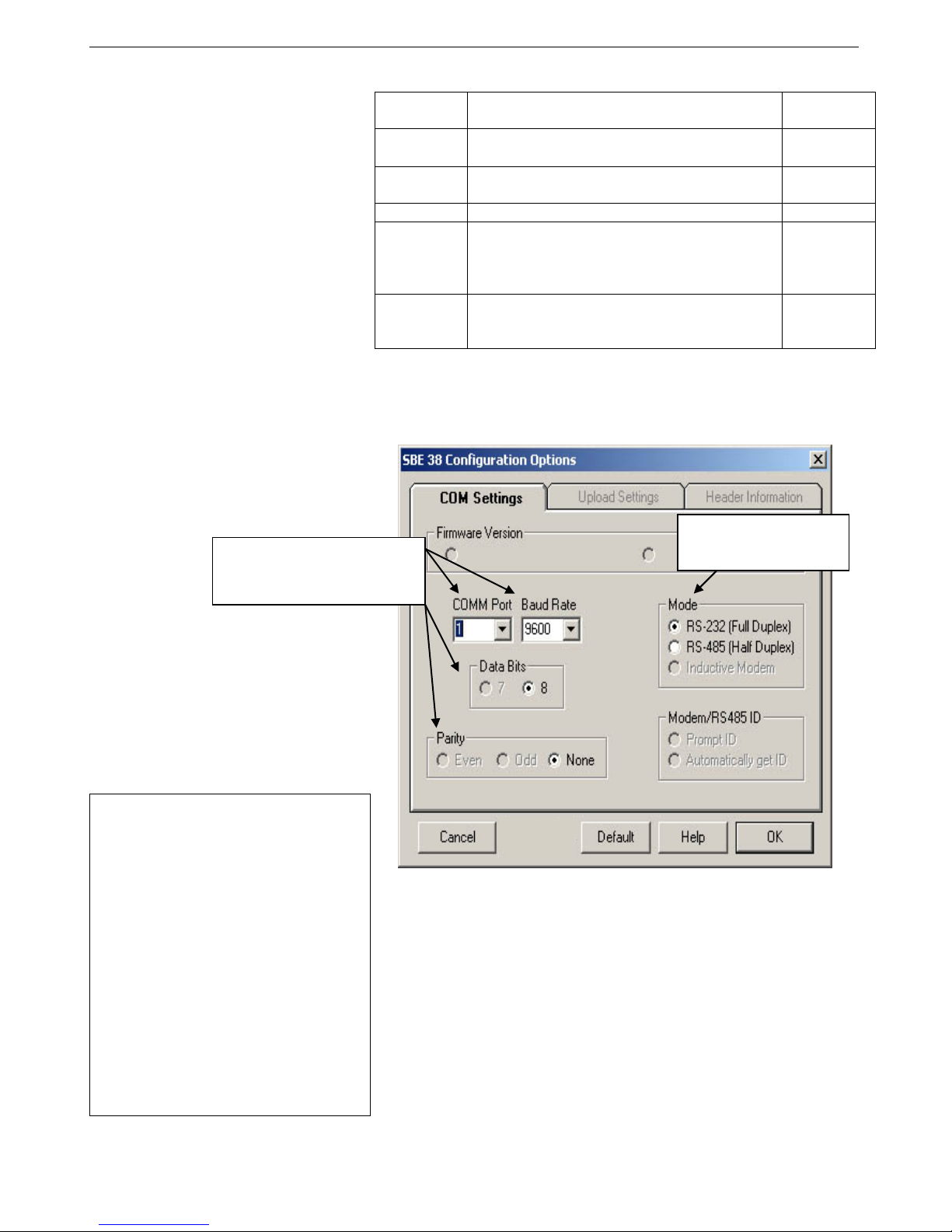
3. In the Configure menu, select SBE 38. The dialog box looks
like this:
Make the selections in the Configuration Options dialog box:
•COMM Port: COM 1 through COM 10, as applicable
•Baud Rate: 9600 (documented on Configuration Sheet)
•Data Bits: 8
•Parity: None
•Mode: RS-232 (Full Duplex) or RS-485 (Half Duplex)
Click OK to save the settings.
Computer COM port, baud rate,
data bits, and parity for
communication between computer
and SBE 38
Interface for communication
between computer and
SBE 38
Notes:
•SEATERM’s baud rate must be the
same as the SBE 38 baud rate (set
with Baud=). Baud= is factory-set to
9600, but can be changed by the user
(see Command Descriptions in
Section 4: Deploying and Operating
RS-232 SBE 38).
•When you click OK, SEATERM saves
the Configuration Options settings to
the SeaTerm.ini file in your Windows
directory. SeaTerm.ini contains the last
saved settings for each instrument.
When you open SEATERM and select
the desired instrument (SBE 38, 39,
etc.) in the Configure menu, the
Configuration Options dialog box
shows the last saved settings for that
instrument.
15

Manual revision 013 Section 3: Preparing SBE 38 for Deployment SBE 38
12
4. In the Communications menu, select Options / Cycle baud
when connecting.
5. Click Connect on the Toolbar. SEATERM tries to connect to the SBE 38
at the baud set in Step 3. If it cannot, it cycles through all other possible
baud rates to try to connect. When it connects, the display looks like this:
SBE 38 V 1.4 S/N 0090 (this line may not appear)
S>
This shows that correct communications between the computer and the
SBE 38 has been established.
If the system does not provide the S> prompt:
•Click Connect again.
•Verify the correct instrument was selected in the Configure menu and
the settings were entered correctly in the Configuration Options
dialog box. Note that the baud rate’s factory setting is documented on
the Configuration Sheet in this manual.
•Check cabling between the computer and the SBE 38.
6. Display SBE 38 status information by clicking Status on the Toolbar. The
display looks like this:
SBE 38 V 1.4 S/N = 0090
NAVG=1
Not sampling data
Automatically start sampling on power up
Default interface is RS-232
7. Command the SBE 38 to take a sample by typing TS and pressing the
Enter key. The display looks like this if the output format was set to
converted data (Format=C) with 4 digits to the right of the decimal place
(Digits=4):
23.7658
where 23.7658 = temperature in degrees Celsius
This number should be reasonable; i.e., room temperature.
The SBE 38 is ready for programming and deployment.
Note:
See Appendix III: RS-485 Interface
for details on sending commands to
an SBE 38 with optional RS-485
interface.
16

Manual revision 013 Section 4: Deploying and Operating RS-232 SBE 38 SBE 38
13
Section 4:
Deploying and Operating RS-232 SBE 38
This section includes:
•system operation description, including example sets of
operation commands
•baud rate, cable length, and power limitations
•detailed command descriptions
•data formats
•instructions for deploying and recovering the SBE 38
Sampling Modes
The SBE 38 has two sampling modes:
•Polled Sampling – take a single sample on command
•Continuous Sampling – sample continuously; start when power is applied
or on command, depending on the setup
Descriptions and examples follow for an SBE 38 with RS-232 Interface. Note
that the SBE 38’s response to each command is not shown in the examples.
Review the sampling modes and the commands described in Command
Descriptions before setting up your system.
Polled Sampling
The SBE 38 takes one sample of data on command. Transmission of data to
the computer is dependent on the particular command used.
Example: (user input in bold)
Apply power and establish communications. Set up to average 4 measurements per sample and output converted
data with 3 digits after decimal place. Command SBE 38 to take a sample and send data to computer.
(Apply power and then click Connect on Toolbar.)
S>NAVG=4
S>FORMAT=C
S>DIGITS=3
S>DS (to verify setup)
S>TS
Note:
See Appendix III: RS-485 Interface
for details on deploying and
operating an SBE 38 with optional
RS-485 interface.
17
Table of contents
Popular Thermometer manuals by other brands


Klein Tools
Klein Tools IR10 instruction manual

Craftsman
Craftsman 50466 owner's manual

Hanna Instruments
Hanna Instruments HI 151-02 instruction manual

Exergen
Exergen TemporalScanner TAT-2000 Series manual

Clas Ohlson
Clas Ohlson ST-9245-300 manual

Sterilize+
Sterilize+ NON TOUCH THERMOMETER quick start guide


