SEA Praha GSM-R4-DIN User manual

GSM-R4-DIN_EN (Version 1.02; 2016-04-06) Page #1 of 5
GSM-R4-DIN, GSM-R4-DINB
1. Introduction
The GSM-R4-DIN and GSM-R4-DINB (
GSM rele4
for short) are designed to be
mounted on a DIN rail into a switchboard.
GSM rele4
can control two
independent electrical circuits in a building e.g. circuit of an accumulator stove and
circuit for garage gate control. The control is made via SMS messages or by ringing.
After installation into an electrical box insert a SIM card of any GSM operator and the
device is ready to operate.
GSM rele4
has 2 galvanically isolated digital outputs with a semiconductor
switch, which can control directly low power circuits up to 230VAC/90mA. It’s possible
to control directly e.g. a thermoregulator circuit of a gas boiler or a coil of one phase
contactor 230V AC. The contact of the contactor can then control either one phase
high power appliance (e.g. electrical radiator) or a coil of three phase contactor of an
accumulation stove.
GSM rele4
has also 2 analog inputs for temperature measuring and 2 digital
inputs which can be activated by a contact from 4V power provided by
GSM rele4
or
by an external voltage 3 to 30V DC.
GSM rele4
has built in two automatic
regulators which use analog inputs from temperature sensors to maintain preset
temperature. The temperature of sensors can be readout via SMS.
There is an internal built in Li-Ion accumulator which enables to send an SMS in
case of a power failure and to restore the output status after a power failure. It’s also
possible to monitor the status of inputs and temperatures via SMS during 230 VAC
power failure.
(1) OUTPUT 3, 4 (Y3, Y4) connectors
(2) Pushbuttons + LED (Y3, Y4)
(3) INPUT 1, 2 (X1, X2) LED
(4) INPUT 1, 2 (X1, X2) connectors
(5) DIN rail holder
(6) Temperature sensors connector (T5, T6)
(7) USB connector (for configuration)
(8)
GSM rele4
operation state LED indicators
(9) 230VAC Power supply connector
(10) SIM card and MicroSD card holder
(11) External GSM antenna connector
( - ) Temperature sensor GSM-C-T2
2. Package Content
1 pc
GSM rele4
(order code GSM-R4-DIN or GSM-R4-DINB)
1 pc GSM antenna ANT05S
1 pc temperature sensor GSM-C-T2 (based on KTY81-210), cable - 1 meter
1 pc cable USB 2.0 A-B, 1.8m (order code HW-11.02.8818)
1 pc connector 5.00 mm
2 pcs connector 3.81 mm
1 pc connector 3.81 mm
1 pc connector 3.81 mm
1 pc screwdriver 2 mm
1 pc printed documentation
3. Installation
1. To operate the
GSM rele4
a SIM card of any GSM operator is necessary. SIM card
must be functional and active. Also some credit is necessary if SIM card is pre-
paid. We recommend to deactivate the PIN code for installation.
2. Insert this prepared SIM card (cut off corner first) into a slot on the side of the
GSM rele4
. The SIM card holder is located in a slot on side of
GSM rele4
(close to
GSM antenna connector). The proper insertion is indicated by a slight mechanical
click noise. To remove the SIM card - press the SIM card in direction into the
GSM rele4
until mechanical click. The SIM card can be the freely removed.
3. Now it’s possible to connect the device to 230V AC power supply. If the power
supply is correct, green LED diode POWER SUPPLY goes on. After about 20
seconds, blue LED diode GSM starts flashing with a period 1 per 3 sec.
4. For the first tests of
GSM rele4
the connection of inputs and outputs is not
important. Please keep in mind that the devices connected to OUTPUTS will be
switched on during tests!
5. To test the
GSM rele4
press the pushbutton bellow OUTPUT 3. The green LED
diode for OUTPUT 3 lights ON. Send an SMS from mobile phone (which will be
mainly used to control the
GSM rele4
) in form 1234 Y3 OFF to the telephone
number of the SIM card inserted into the
GSM rele4
. This will switch off the
plugged appliance. The green status LED for OUTPUT3 goes OFF. Simultaneously,
the device automatically sends a confirmation SMS message on performing the
operation. The password 1234 can be changed later in configuration. The
GSM rele4
reacts on the SMS text message from any telephone as long as the
access password matches. The very first one (the sender of the first valid SMS
message) will be remembered as master and will receive messages about events
on
GSM rele4
. This user can also control OUTPUT 4 by “ringing”on the device.
6. Try “ringing” on device. You can make pulse on OUTPUT 4 for approx. 4 seconds
by calling to
GSM rele4
(with default factory setting). The device hangs up the call
and makes pulse on the OUTPUT 4. This pulse can be used for example for
opening entrance gate. To test this function call from the phone (which was used
to send the first test SMS to switch off the OUTPUT 3). The pulse is indicated by
green LED.
7. Try regulation. You can send SMS in form of 1234 Y3 REG 25 to command the
device to maintain temperature to 25°C. The range of regulation is between 0°C
and +55°C. Regulation can be canceled by SMS with command 1234 Y3 OFF. By
default the regulation of OUTPUT 3 depends on temperature sensor connected to
analog INPUT T5 (OUTPUT 4 depends on INPUT T6).
8. A default factory setting of the
GSM rele4
can be recovered by an SMS in form
1234 FACTORY. Your setting can be then restored from backup configuration of
SeaConfigurator program.
4. Technical specifications
Parameter
Symbol
MIN.
TYP.
MAX.
Unit
Dimensions
Width
Š
71
mm
Height
V
90
mm
Depth
H
58
mm
Power
supply *1)
Voltage
V
180
230
250
V AC
Current
11
30
mA
Digital inputs
INPUT1, INPUT2
Voltage
VIN
3
12
30
V DC
Current
IIN
3,5
mA DC
Digital
outputs
OUTPUT3, OUTPUT4 - Semiconductor switch OPTO-MOS
Voltage
VOUT
5
230
260
(400)
V AC
(V DC)
Current
IOUT
90
(120)
mA AC
(mA DC)
Analog inputs
2 x temperature sensor GSM-C-T2, Accuracy in range 0 to 30°C ... 1°C
Temperature
-
-30
+55
°C
Temperature
Storage
without supply
3 *2)
Months
Operational
tA
-20
+45
°C
Use
GSM rele4
- DIN inside the rack with IP44 or better!!
*1) Use breaker max. 10 A before
GSM rele4
. For power supply 230VAC use lines min.
1 mm2.
*2) The
GSM rele4
has to be connected to 230VAC power supply every 3 months for
24 hours (due to internal accumulator).
5. Hardware
The front panel of the
GSM rele4
contains a set of status indicating LED
diodes located, pushbuttons for local
control of outputs, connectors for
connecting power supply, input signals,
output signals and temperature
sensors.
5.1 Connectors
GSM rele4
enables to connect 2
external digital inputs, 2 external digital
outputs and 2 external temperature
sensors GSM-C-T2 with temperature
range from -30°C to +55°C.
The line length of a connected external
temperature sensor is not limited but
the wire has a certain resistance which
influences the measured temperature (16 means 1 °C).
The recommended type of relay for connection of more appliances is GSM-RELE-OUT.
When using the
GSM rele4
for a gate control by a phone ring, it’s possible to connect
output 3 and COM directly with a pushbutton of the gate control.
Read Technical specifications before connecting external devices! Don’t overload
inputs and outputs.
Examples of connection of
GSM rele4
are placed later in this text.
5.2 Pushbuttons
The
GSM rele4
has two pushbuttons for local control of outputs. Every press of the
pushbutton changes the state of the output.
Before inserting the SIM card into the
GSM rele4
device, we
recommend to turn off setting of the “PIN code”!
Insert the active SIM card (= at least one call was made) to any mobile
telephone and turn off the requirement of setting the PIN. On most mobile
telephones, this option can be found in menu “Setting the telephone
protection”. or “Setup -> Security -> PIN control”.
ATTENTION:
GSM rele4
must be mounted by qualified personnel only!
X2 4VX1
230 VAC
GND
POWER
ERROR
GSM rele4
3 4
ALARM
GSM
1 2
1 2 3 4 5 6
GSM
ANT.
Y3 Y4
T5 T6
1 2 3 4
1 2 1 2 1 2
L1N
EXT
USB
SIM,
uSD
3
1
28
9
6
11
4
7
5
5
10
GSM-R4-DIN_EN (Version 1.02; 2016-04-06) Page #2 of 5
5.3 LED diodes
The front panel of
GSM rele4
contains indication LED diodes POWER, ALARM, GSM,
EXT and LED diodes which indicates status of digital inputs (INPUT1, INPUT2) a
outputs (OUTPUT3, OUTPUT4).
5.4 Battery
GSM rele4
is equipped with backup 3.7 V Li-Ion battery which enables to operate the
GSM rele4
for several hours in normal mode in case of a 230 VAC power failure. (the
battery life time depends on mode of usage). During the battery supply mode the
GSM rele4
the LED POWER blinks at an interval of 1 for 3 seconds.
*) When the battery falls below a certain voltage, the device switches to "Sleeping
mode", in which it can stay up to a month. The
GSM rele4
wakes up of the sleeping
mode, either by applying 230V AC power supply or by change of the logic INPUT 1 or
INPUT 2. *) Not used in this version
5.5 External antenna connector
GSM rele4
is supplied with an external antenna GSM-ANT05S. It is not recommended
to put this type of antenna on metal surface (the signal quality will degrade).
If a
GSM rele4
is used in area with a low GSM signal, it’s possible to use another type
of the antenna with higher gain.
5.6 MicroSD card and data logging
GSM rele4
(version GSM-R4-DIN) can store detailed information of its activities into a
log file on a MicroSD card for later analysis. The MicroSD card reader is located under
the removable cover close to the SIM card reader.
Note: This function requires a license - ask your supplier for details.
6. Configuration
Configuration of the
GSM rele4
can be made in several ways.
6.1
GSM rele
4
- default factory configuration
When the signal on INPUT 3 or INPUT 4 changes, the
GSM rele4
sends an SMS
message to the main users (to the telephone number from which it received the first
valid command). The input signal must be stable for certain time (approx. 1 sec) to
avoid sending unwanted SMS messages in case of interference on the input.
Temperature regulators are set up so that the OUTPUT 3 is regulated by temperature
sensor on INPUT T5 and OUTPUT 4 from the temperature sensor on INPUT T6.
6.2 Configuration of
GSM rele
4
from PC via USB
The configuration (parameter setting) can be done using program SeaConfigurator.
E.g.
GSM rele4
can be set to inform of the 230V AC power failure or restoration via
SMS or by ringing.
SeaConfigurator can be downloaded on the web page:
http://www.seapraha.cz
Fill in the word GSM-R4-DIN or GSM-R3-DINB to the search field.
6.3 Configuration of
GSM rele
4
via SMS
Some parameters of
GSM rele4
can be configured via SMS:
List of configuration SMS commands:
Command
Parameter
Meaning
FACTORY
-
All parameters are setup to factory default.
USER DIS
Phone number e.g.:
+420777777447
A “disabled” flag for the user is set. If and user is
not in the list an error is indicated.
USER CHANGE
Phone numbers
e.g.:
+420777777447
+420123456789
The first phone number in the list is replaced by
the second number. If the first phone number
does not exist in the list or the second is already
in the list an error is indicated.
CODE ADD
Password
e.g.
1234
New user with specified password is added
(password max. 20 digits). If the password
already exists an error is indicated. If the
password already exists and the user is disabled,
the user is activated and no error is indicated.
CODE DIS
Password e.g.:
9876
A “disabled” flag for the user is set. If the user is
not in the list an error is indicated.
CODE CHANGE
Passwords
e.g.
1234 9876
The first password in the list is replaced by the
second password. If the first password does not
exist in the list or the second is already in the list
an error is indicated.
1234 FACTORY … All parameters of
GSM rele4
will be setup up to factory default
1234 USER DIS +420777777497
…the user with phone number +420777777497 is disabled
1234 USER CHANGE +420777777497 +420777777451
…the phone user’s number is changed from +420777777497 to +420777777451
1234 CODE ADD 9876 …the new password 9876 is added
1234 CODE DIS 9876 …the password 9876 is disabled
1234 CODE CHANGE 1234 9876
…the first password 1234 is changed to new second password 9876
7.
GSM rele
4
- Control
7.1 Output control by “ringing”
GSM rele4
is set by the manufacturer to switch ON an OUTPUT 4 for 4 seconds when
any user from the list of users calls to
GSM rele4
phone number. This pulse is useful
for an opening of an entry gate. Test this function by a call to
GSM rele4
from your
mobile phone (it’s important to send a valid command SMS to
GSM rele4
from your
mobile phone if have inserted a “new” SIM card to
GSM rele4
).
GSM rele4
rejects a call and at the same time generates a pulse on an OUTPUT 4.
7.2 Remote control of
GSM rele
4
via SMS
GSM rele4
is controlled via SMS of the GMS network. Text SMS are in form:
<PASSWORD> <COMMAND> [<COMMAND >]
Each command is preceded by Yn, where n is the number of controlled output. If
output is not specified, the OUTPUT 3 (Y3) is used as default. Commands ON and
Y3 ON and Y3ON has the same meaning.
Example:
1234 Y3 ON …an appliance connected to OUTPUT 3 will be switched on,
confirmation message will be sent back
1234 Y4 OFF NOBACK …an appliance connected to OUTPUT 4 will be switched off,
NO confirmation message will be sent back
Password (access code)
Password is a main security item for
GSM rele4
control. Command SMS are accepted
from any phone number. It means anybody who knows the password and the phone
number can control the
GSM rele4
. The password is a string of digits (1 to 20) which
must be on the beginning of any command SMS. Otherwise the SMS will be ignored. A
text before the password is automatically ignored. It is useful when command SMS are
sent from Internet GSM gates.
Factory setting of a password is:
1234
LED
COLOR
Meaning
Dark
Light
Blink 1 per 3sec
1:1
EXT
orange
-
-
-
-
SUPPLY
green
Device
switched off
Supplied
from
230VAC
Supplied from
battery,
NO 230VAC
-
ERROR
red
Standard
operation
GSM error
-
uSD card
error
ALARM
red
Function
“Alarm”
NOT active
Any sensor
activated
ALARM!
Function
“Alarm”
active
Function
“Alarm”
preparation
GSM
blue
no GSM signal
Other GSM
error
operational
Fast:
Connecting
to GSM
Slow:
SIM card
problem
INPUT1
INPUT2
green
Input not
activated
Input is
activated
-
-
OUTPUT3
OUTPUT4
green
Output
switched off
Output
switched on
Inverse blinking
during
regulation
mode
-

GSM-R4-DIN_EN (Version 1.02; 2016-04-06) Page #3 of 5
Command
This part of a message specifies a requested action. See the following table for
available commands.
GSM rele4
commands are not a case sensitive, it’s possible to
use upper letters as well as lower letters.
Command
Parameter
Meaning
Y3 ON
-
An OUTPUT 3 will be switched on.
(Use Y4 ON for OUTPUT 4)
ON
-
This command acts in exactly the same way as
command ON3
Y3 OFF
3 or 4
An OUTPUT 3 will be switched off.
(Use V4 OFF for OUTPUT 4)
OFF
This command acts in exactly the same way as
command OFF3
Y3 PULSE
Y3 RESET
4
Generates 4 sec pulse on OUTPUT 3
Generates 4 sec reset on OUTPUT 3
PULSE
RESET
These commands act in exactly the same way as
command PULSE3 / RESET3.
REG
0 to 55
Setting of requested temperature and starts
regulation mode.
STATE
-
Request of status SMS (state of inputs, outputs,
temperatures, signal quality and credit).
Tip:
It’s possible to use more commands in one SMS. Commands are separated by a
space (see an example).
Examples:
1234 ON … an appliance connected to OUTPUT3 will be switched on
1234 Y3 ON … an appliance connected to OUTPUT3 will be switched on
1234 Y4 ON … an appliance connected to OUTPUT4 will be switched off
1234 Y4 PULSE 5 … an OUTPUT 4 will be switched on and then after 5 seconds
will be switched off (Notes: if an output is already switched on, it will be just switched
off after 5 seconds)
1234 Y4 REG 5 … requested temperature for the function temperature
regulation of OUTPUT 4 will be set to + 5°C
an example of more commands in one SMS:
1234 Y3 OFF Y4 REG 25 … An OUTPUT 3 will be switched off and the requested
temperature will be set to 25°C
Confirmation
If a command message contains a valid password (access code) the
GSM rele4
returns
a confirmation message which informs if a command was accepted (see chapter Status
SMS). If you don’t want a confirmation message (e. g. when sending a command SMS
from the Internet GSM gates) add a command “NOBACK”.
Command
Meaning
NOBACK
No confirmation SMS will be sent
Example:
1234 Y3 ON NOBACK … an appliance connected to OUTPUT3 will be
switched on. NO status message will be sent back
7.3 Local control using pushbuttons
GSM rele4
has 2 pushbuttons for local control of outputs (see. Chapter 5.2)
7.4 Status SMS message
Whenever the command SMS contains valid password the
GSM rele4
send back Status
message.
Parameter Credit is sent only in case of pre-paid SIM cards. If the actual value of
Credit cannot be readout from operator, the last known value is listed in parentheses
e.g. Credit=(243.15 Kc).
Example of status SMS
Explanation
Base station: Y3 REG 25/27'C OK;
Device name:
Command confirmation: Y3 REG27
X1=ON
INPUT 1 state
X2=ON
INPUT 2 state
Y3=ON(REG 25/27'C)
OUTPUT 3 state
Y4=OFF
OUTPUT 4 state
T5=25'C
INPUT T5 actual temperature
T6=26'C
INPUT T6 actual temperature
Power=Failure
Power supply from 230VAC / (from battery)
Signal=38%
GSM signal level
Credit=243.15 Kc
Credit on pre-paid SIM card
7.5 Remote Control via the application for OS
Android
The application for OS Android called SeaControl is used for control and monitoring
of GSM RELAY, you can download it for free. For detailed information and downloading
the application, go to www.seapraha.cz and write GSM-CONTROL into the searchbox.
This application communicates with a GSM relay via SMS.
8. Warranty
General warranty period is 12 months after purchase, when eventual malfunction
device will be repaired free of charge in SEA company while shipping to SEA is paid by
customer and SEA pays for shipping back to customer. For SW there is 24 months
warranty under following conditions:
Both CPU and PC software is sold “as is”. The software was created by the best
software engineers in SEA and was carefully tested both in SEA and also by SEA
customers using GSM applications products made in SEA. In spite of making all
possible to get error free software it can happen, that the software in CPU or PC
programming SW or their mutual interaction has some error under some specific
conditions. If such error is found and the description of the problem
including configuration file is sent by E-mail to SEA ltd., the error is
removed free of charge and SEA will send new SW by E-mail to
customer.
SEA ltd. has NO RESPONSIBILITY for any damage, lost, costs and
any other problems direct or inducted, caused by such SW error, by
eventual device malfunction from any reason or by undelivered SMS
from the device.
CE Declaration of conformity
in accordance with the Radio and Telecommunications Terminal Equipment Directive 1999/5/EC (R&TTE) and Directive
2011/65/EU (ROHS).
We SEA, spol. s r.o., Dolnoměcholupská 1537/21, CZ 102 00 Praha 10, Czech Republic, ID: 47117931 (manufacturer)
declare under our sole responsibility, that product device for remote control and monitoring type GSM-R4-DIN
is in conformity with the following standards:
health and safety: EN 60 950-1:2005+A1:2009 EN 60 950-1:2006+A11:2009+A1:2010+A12:2011
EMC: ETSI EN 301 489-1 ETSI EN 301 489-7 v1.3.1
radio frequency: EN 301 511 v 9.0.2
The last two digits of year in which the CE marking was affixed:
14
Place of issue: Praha Name: Ing. Mario Vejlupek
Date of issue: 18.12.2014 Grade: Technical director
GSM-R4-DIN_EN (Version 1.02; 2016-04-06) Page #4 of 5
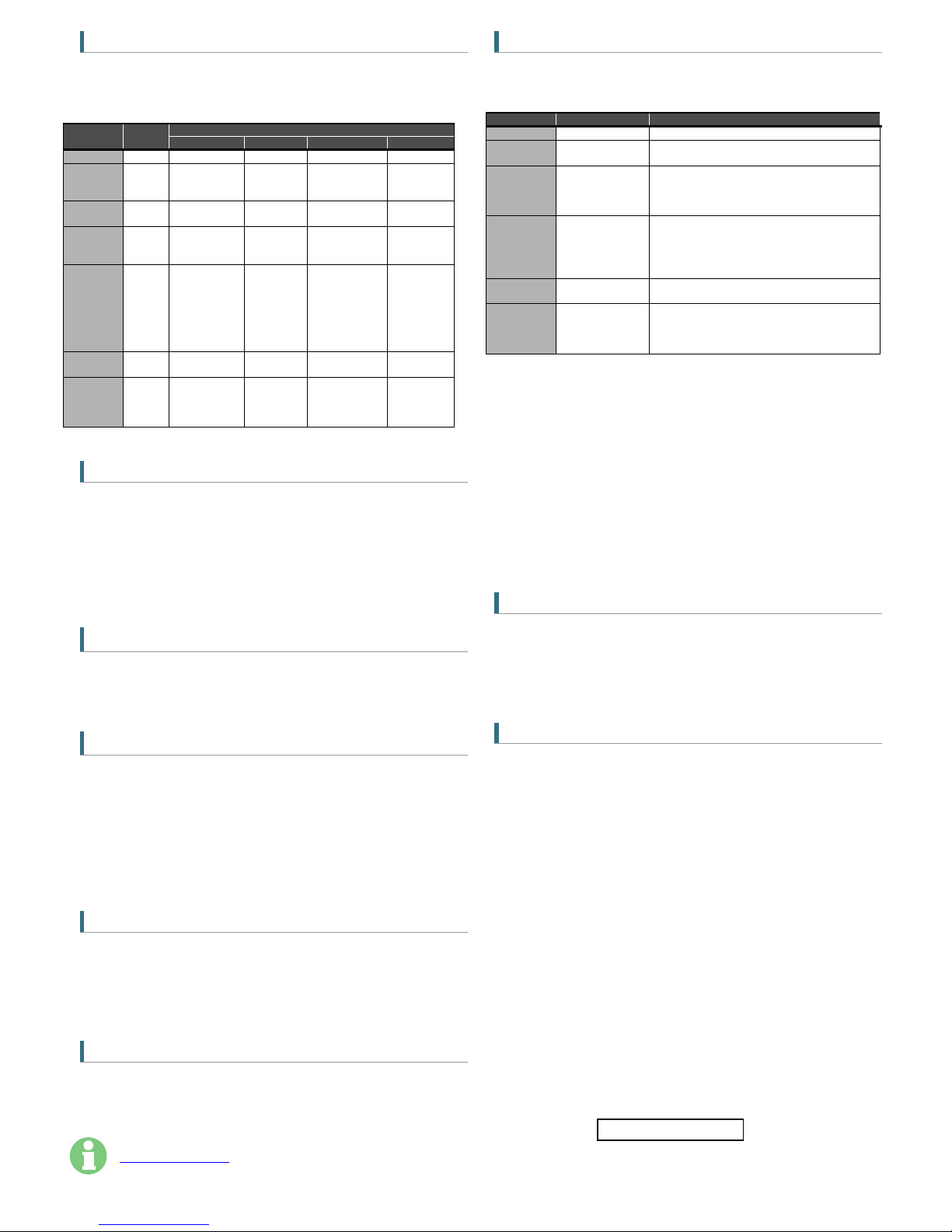
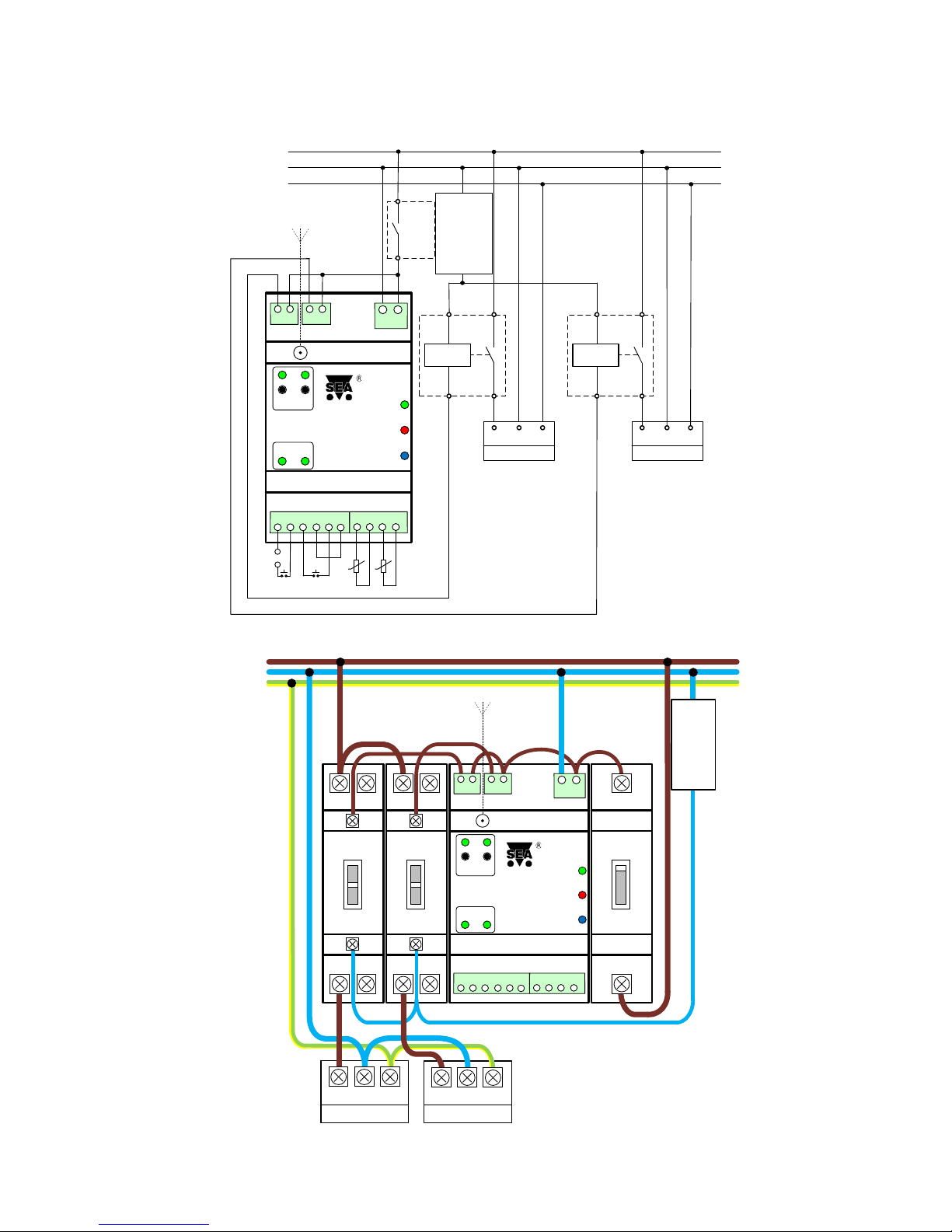
9. Examples of connection
An example of usage
GSM rele4
. With two power outputs are controlled two electrical appliances such as heating and boiler with contactors, digital inputs detect voltage on
switching / opening a door contact and two analog inputs T5, T6 measure temperatures.
The schematics calculate with usage of the “Load Management Signal”. Logic input No. 1 is activated by supplying an external 12V DC logic input and input 2 uses internal 4V DC
and connects directly to the terminal door contact. The 2 analog inputs T5, T6 connect the temperature sensors. Outputs of the
GSM rele4
control contactors of heater and boiler.
VF
1 2 3 4 5 61 2 3 4
1 21 2
NAPÁJENÍ
GSM
GSM RELÉ 2 - DIN
VÝSTUP
VSTUP
1 2
3 4
1 2 3
4V t1 t2
Contactor
1
230V AC PE
N
L
Contactor
2
L N PE
BOILER
L
1 2 3 4 5 61 2 3 4
POWER
GSM RELE4 - DIN
OUTPUT
3 4
T5 T6
1
1 21 2 1
ALARM
GSM
INPUT
1 2
GSM
Breaker
21
ττ Tempe-
rature
sensors
External
supply
12V DC
+
Y3 NL
Antenna
L N PE
HEATING
HDO*)
Signal
from Load
Manage-
ment
Y4
X1 ┴X2
+
-
Electrical schematics
VF
L N PE
HEATING
L N PEPE
BOILER
1 2 3 4 5 61 2 3 4
230V AC PE
N
L
POWER
GSM RELE 4 - DIN
OUTPUT
3 4
T5 T6
BREAKER
1
1 21 2 1
CONTACTOR
I
O
AUTO
I
O
ALARM
GSM
INPUT
1 2
CONTACTOR
I
O
AUTO
HDO
21
V1aV1b 4V
V2b
V2a GND
V3aV3b V4aV4b NL
GSM
Antenna
HDO
*)
Signal
from
Load
Manage-
ment
Wiring

GSM-R4-DIN_EN (Version 1.02; 2016-04-06) Page #5 of 5
10. Frequently Asked Questions (FAQ)
What is necessary to use the
GSM rele4
Good quality GSM signal in a place where
GSM rele
4
will be used (at least 2 bars on your mobile phone)
Sufficient credit on a pre-paid SIM card
No phone call redirection
The user has to know to operate his mobile phone (PIN usage deactivation)
Note: Users who knows to operate older version of GSM RELAY version 2 can use older SMS command form: E.g. 1234 ON3 OFF4
Problem description
Possible reason
Solution
LED GSM (blue ) flashes 1:1 (slow)
SIM card is not functional
New SIM card is not
activated yet
Low credit on a pre-paid
SIM card
Test the SIM card in your mobile phone. Try to make a call and receive a call from another mobile phone.
Try to send a receive SMS message.
Switch off using PIN on a SIM card. Cancel all call redirection for a SIM card. (Ask your mobile operator
for help if necessary)
New SIM card has to be activated. (Ask your mobile operator for help if necessary)
Check credit on a pre-paid SIM card
(Ask your mobile operator for help if necessary)
LED GSM (blue) is off (dark)
LED ERROR (red) is on
(lights permanently)
Weak/poor GSM signal
Test the SIM card in your mobile phone. The mobile phone should show the signal level at least 2 bars
The pulse on an output is not generated
based on incoming ring signal (e. g. for
a gate opening)
The incoming phone calls
for a SIM card are
redirected
Cancel all phone call redirections for the SIM card
The temperature from an external
temperature sensor is wrong
Too long lines to an
external temperature
sensor
The accuracy of temperature depends on a line length to an external temperature sensor (16 Ohms
means 1°C). Use thicker wires to temperature sensor
This manual suits for next models
1
Table of contents
Popular Other manuals by other brands

Aion Electronics
Aion Electronics ANTIPODE manual

Dometic
Dometic MagicSafe MSG150 Installation and operating manual

Gardena
Gardena 1266 operating instructions

Superwinch
Superwinch SI Series Electric user manual

Schweitzer Engineering
Schweitzer Engineering SEL-300G quick start guide

BORLA
BORLA 60605 installation guide

Radica Games
Radica Games Air Force I-COMBAT 71039 instruction manual

RFL Electronics
RFL Electronics RFL 9300 instruction manual

Datalogic
Datalogic DLR-BT001 Series Product reference guide

Fourtec
Fourtec MicroLite quick start guide

Brant Radiant Heaters
Brant Radiant Heaters Patio-Pal PH Series Installation, operation, maintenance and parts manual

Chauvet
Chauvet Panel user manual


