Sea Tel Cosel 150W User manual


Procedure, Field Replacement, Cosel 150W Power Supply Kit
Page1of6
Document No
135263 Rev B
Copyright © Sea Tel, Inc 2011 - The information contained in this document is proprietary to Sea
Tel, Inc.. This document may not be reproduced or distributed in any form without prior written
consent of Sea Tel, Inc.
1. BriefSummary:
TroubleshootingdocumentfordiagnosingafaultwithandreplacingtheCosel150Wpowersupplyunit.
2. Checklist:
VerifyACVoltageispresententeringthepowersupply
VerifyDCVoltageispresentexitingthepowersupply
3. TheoryofOperation:
TheCosel150Wpowersupplyisswitchmode&willconverteither110VACor220VACinto24VDC.Thiscomponentis
universallyusedintheDAC‐2202,XX97&XX06pedestalpowersupplies,XX09&XX10PCU’s&NJRC24VBUCPower
suppliesmeaningonlyasingleunitisneededasasparetocoverawiderangeofapplications.
4. Troubleshooting:
1.Measuretheinputvoltageintothepowersupplyonthe2pins
totherightoftheconnectionblock,110‐240voltsACshouldbe
present.IfnoACvoltageispresentverifytheunitisswitchedon.
Ifthereisstillnovoltagepresenttroubleshootthesource.
2.Nowmeasuretheoutputvoltagefromthepowersupplyonthe
2pinstotheleftoftheconnectionblock,theoutputshouldbe
24VDC.
IftheunitsACinputhasbeenverified&the24VDCisnotpresent,thepowersupplyisdefective&needstobereplaced.
Ifthepowersupplyisoutputtingthe24VDCconsistentlythenthepowersupplyisoperational&theproblemlies
elsewhere(possiblefailurewiththePCU,DACmotherboardorharnessconnection).

Procedure, Field Replacement, Cosel 150W Power Supply Kit
Page2of6
Document No
135263 Rev B
Copyright © Sea Tel, Inc 2011 - The information contained in this document is proprietary to Sea
Tel, Inc.. This document may not be reproduced or distributed in any form without prior written
consent of Sea Tel, Inc.
5. ReplacingtheDAC‐2202PowerSupply:
5.1. Tools.
#1PhillipsScrewdriver
Loctite242
5.2. Procedure.
ProcedureforreplacingtheDAC‐2202powersupply,SeaTelkitpartnumber:135341(powersupplypartnumber:
125343‐6).
*Caution:DisconnectthevesselsACVoltagetotheDAC
priortoperformingthebelowprocedure.
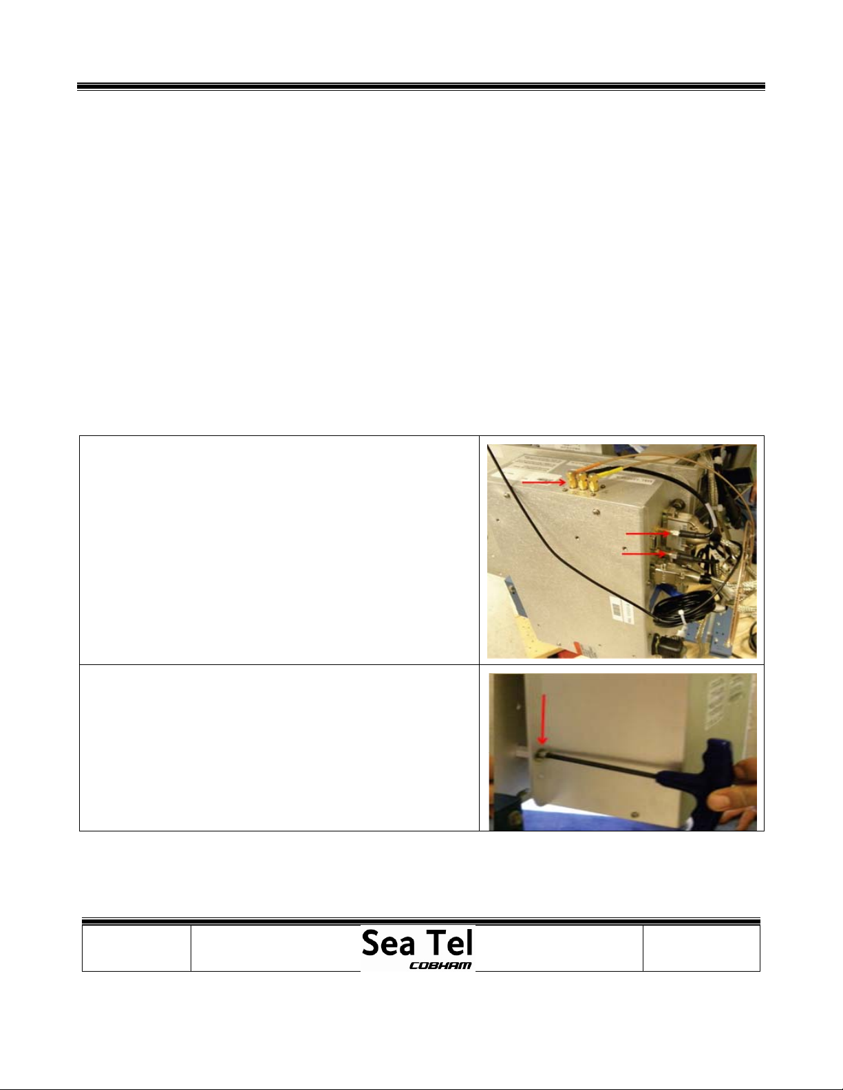
1.Usinga#1Phillipsscrewdriverundothe6screwsretaining
theDAClid&removeit.Savethehardwareforfutureuse.
2.NotetheorientationoftheAC&DCcablesonboththe
powersupplyunit&theswitch.
3.DisconnecttheACpowercablesfromthepowerswitch.
4.TurntheDACassemblyover&usinga#1Phillips
screwdriverremovethetwoscrewssecuringthepower
supplytothebaseoftheDACshell.

Procedure, Field Replacement, Cosel 150W Power Supply Kit
Page3of6
Document No
135263 Rev B
Copyright © Sea Tel, Inc 2011 - The information contained in this document is proprietary to Sea
Tel, Inc.. This document may not be reproduced or distributed in any form without prior written
consent of Sea Tel, Inc.
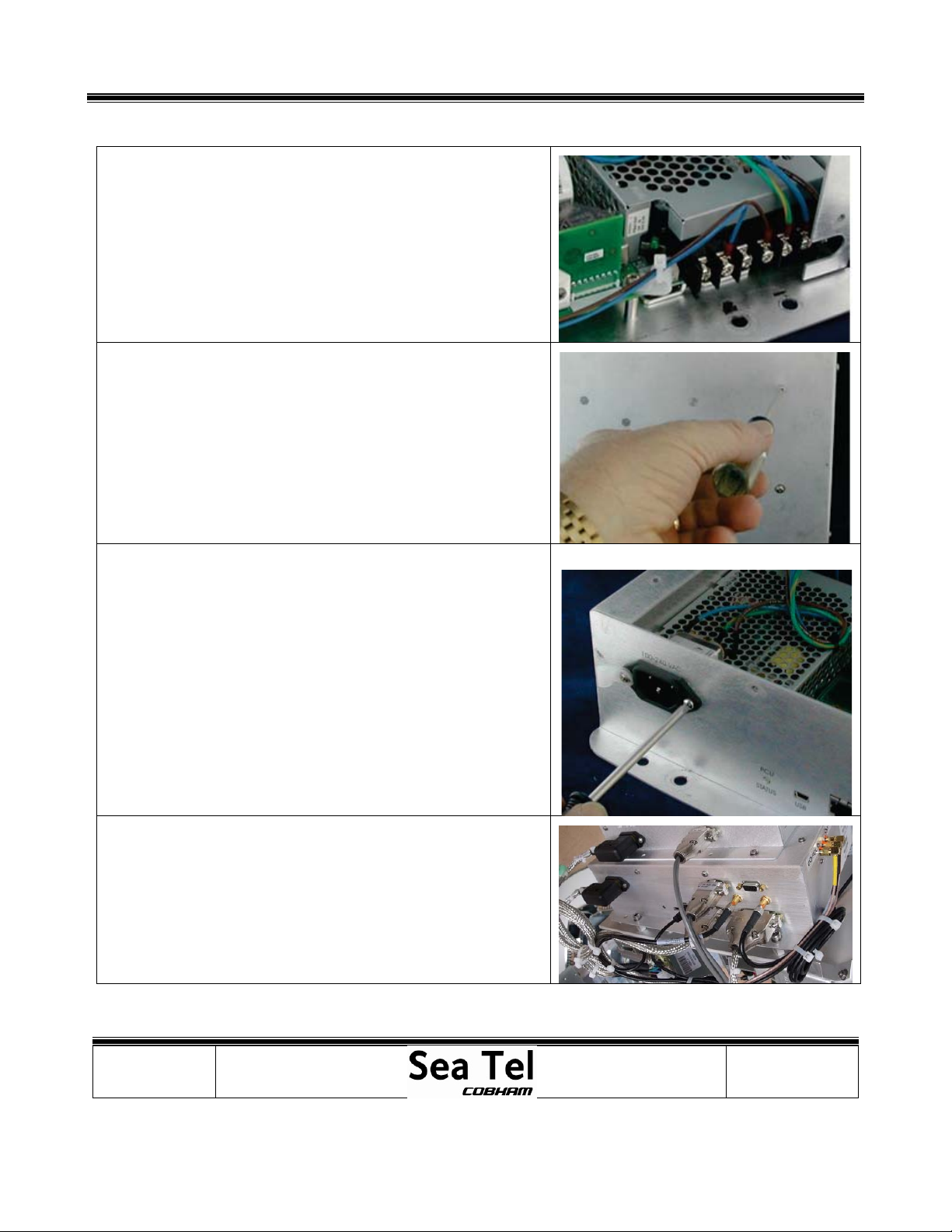
5.TurntheDACthecorrectwayup&removethetwoscrews
securingthepowersupplytothesideoftheDACshell.
6.Raisethepowerssupplyunittoallowclearance&remove
thecover,thenremovetheDCpowercables.
7.NowremovetheACcablesfromthedefectivepower
supply&connectthemtothereplacementunit.
8.ConnecttheDCcablestothepowersupplyasshownon
theright.
9.Nowinstallthe4screwstosecurethepowersupplyinto
theDACshell.Installtheplasticcoverovertheterminal
connectionsandreconnecttheACcablestothepower
switchasshownontheright.
10.ReinstalltheDAClid&securewiththe6screwsremoved
inthefirststep,applyLoctite242tothethreads.
Procedure, Field Replacement, Cosel 150W Power Supply Kit
Page4of6
Document No
135263 Rev B
Copyright © Sea Tel, Inc 2011 - The information contained in this document is proprietary to Sea
Tel, Inc.. This document may not be reproduced or distributed in any form without prior written
consent of Sea Tel, Inc.
6. ReplacingtheXX09andXX10PedestalPowerSupply:
6.1. Tools.
5/16”(8mm)Wrench/Spanner
2mmFlatBlade(Terminal)Screwdriver
Snips/Cutters
3/16”(5mm)AllenWrench/Key
#1PhillipsScrewdrivers
CableTies/TieWraps
Loctite242
6.2. Procedure.
ProcedureforreplacingtheXX09Pedestalpowersupplyunit,SeaTelpartnumber:125343‐6.ThePCUwillhavetobe
removedfromtheequipmentframetoreplacethepowersupply.
6.3. RemovingthePCU.
*CAUTION:Powerdownthepedestalbeforefollowingthis
procedure.
1.Usinga5/16”(8mm)wrenchremovethe3coaxcablesfromthe
switchassemblymountedinthePCU.
2.Usinga5/16”(8mm)wrenchremovethe2coaxcablesfromthe
400MHzmodemPCB(takingnoteofwheretheSMAconnectors
needtobereconnected).
3.Usinga2mmflatbladescrewdriver,removetheD‐Sub
connectors.
4.UnplugtheGPScable.
5.Usingcutterscutthelargecabletieonthepowercordconnector
anddisconnectthepowercord.
6.Usinga3/16”(5mm)Allenwrench,removethe4capheadscrews
thatmountthePCUtotheequipmentframe.Retainthesescrews
forfutureuse.
7.WiththePCUremovedfromtheequipmentframe,refertothe
followingprocedureregardingremovingthecoverfromthe
assembly.

Procedure, Field Replacement, Cosel 150W Power Supply Kit
Page5of6
Document No
135263 Rev B
Copyright © Sea Tel, Inc 2011 - The information contained in this document is proprietary to Sea
Tel, Inc.. This document may not be reproduced or distributed in any form without prior written
consent of Sea Tel, Inc.
6.4. RemovingthePCUCover.
1.Usinga#1Phillipsscrewdriver,
removethe2Phillipsscrewsinthelip
edgeabovetheconnectors.
2.Removethe4Phillipsscrewsonthe
topofthePCU.
3.Removethe2Phillipsscrewsonthe
backsideofthePCU.
4.Retainallofthescrewsforfutureuse.
5.RemovethecoverofthePCU
Procedure, Field Replacement, Cosel 150W Power Supply Kit
Page6of6
Document No
135263 Rev B
Copyright © Sea Tel, Inc 2011 - The information contained in this document is proprietary to Sea
Tel, Inc.. This document may not be reproduced or distributed in any form without prior written
consent of Sea Tel, Inc.
6.5. ReplacingtheXX09andXX10PedestalPowerSupply.
1.DisconnectthePowerSupplyWires
LargeBlue–A/C(N)
LargeBrown–A/C(L)
Greenw/Yellowstripe–FG
SmallBrown(GND)–V‐
NC
SmallBlue(+24VDC)‐V+
NC
2.FromthebottomofthePCU,usea#1Phillipsscrewdriverto
removethe2PhillipsscrewsthatmountthePowerSupplyinsidethe
PCU.Retainthesescrewsforfutureuse.
3.FromtheoutsideofthePCU,removethe2Phillipsscrewsthat
mountthePowerreceptacle.Retainthesescrewsforfutureuse.
4.Removethereceptacle.
5.RemovethedefectivePowerSupply.
6.InstallthereplacementPowerSupply.
7.ApplyLoctite242tothe2PhillipsscrewsandmountthePower
SupplyintothePCU.
8.ApplyLoctite242tothe2PhillipsscrewsandreinstallthePower
receptacleintothePCU.
9.ReconnectthePowerSupplyWiresasshownabove.
10.Ifallrepairworkisnowcompleted,reinstallthePCUcoverand
thePCUtotheequipmentframe.
11.SecurethepowercableintothePCUA/Csocketusingacabletie.
Table of contents
Popular Power Supply manuals by other brands

Ultra Products
Ultra Products ULT31840 Features

TDK-Lambda
TDK-Lambda GH10-150 Product Safety & Installation Manual

Global Specialties
Global Specialties 1310 instruction manual

Sharkoon
Sharkoon WPM Bronze 400 manual

Stahl
Stahl ISpac 9143/10-065-150 0 Series operating instructions

Fisher Scientific
Fisher Scientific Midi300V/4 instruction manual

PROLiNK
PROLiNK PPS70 Specifications

Matsusada Precision
Matsusada Precision DOS Series instruction manual

Xantrex
Xantrex XPower Powerpack 400 Plus, 400 R owner's guide

Altronix
Altronix SMP7 quick start guide

Paradyne
Paradyne 496-15149 installation instructions

Extron electronics
Extron electronics PS Series Specification sheet


