Seabreeze WTS32 User manual
950-0160revB February 2, 2012
WTS32
Wireless Thermostat
and Receiver
Installation /
Operation
Manual

______________________________________________________WTS32 Wireless Thermostat
950-0160revB February 2, 2012
i
TABLE OF CONTENTS
Thermostat (transmitter)………………………………………………………………………………………………………………….. 1
LCD Display……………………………………………………………………………………………………………………………….. 2
Key Functions……………………………………………………………………………………………………………………………... 3
Receiver (controller)………………………………………………………………………………………………………………………. 4
Features……………………………………………………………………………………………………………………………………. 5
Systems…….……………………………………………………………………………………………………………………………… 6
Specifications………………..……………………………………………………………………………….……………………………. 8
Wiring Schematics for Conventional Systems…………………………………………………………….…………………………… 10
Wiring Schematics for Heat Pump Systems…………………………………………………………………………………………… 14
Installation…………………………………………………………………………………………………………………………………. 16
Charging the Thermostat………………………………………………………………………………………………………………… 16
Mounting Transmitter and Receiver…………………………………………………………………………………………………….. 17
Standard Terminal Outputs………………………………………………………………………………………………………………. 19
Heat Pump Terminal Outputs……………………………………………………………………………………………………………. 20
Receiver Wiring Cover Installation………………………………………………………………………………………………………. 21
Outdoor Sensor Wiring……………………………………………………………………………………………………………………. 22
Sea Breeze PTAC Receiver Installation………………………………………………………………………………………………… 25
Matching Thermostat to Receiver……………………………………………………………………………………………………….. 26
Configuration Menu……………………………………………………………………………………………………………………….. 27
Programming……………………………………………………………………………………………………………………………….. 34
Setting Clock and Day………………………………………………………………………………………..……………………………. 36
Temporary Manual Override………………………………………………………………………………………………………………. 37
Scheduled Override ……………..………………………………………………………………………………………………………… 38
Permanent Override…………..……………………………………………………………………………………………………………. 38

______________________________________________________WTS32 Wireless Thermostat
950-0160revB February 2, 2012
ii
Auto Changeover….………………………………………………………………………………………………………………………… 39
Filter Monitor……….………………………………………………………………………………………………………………………… 39
Auto Recovery…………………………………………………………………………………………………………………………..…… 40
Keypad Lock…………………………………………………………………………………………………………………………………. 40
Error Mode…………………………………………………………………………………………………………………………………. 41
Low Battery Warning……………………………………………………………………………………………………………………… 41
Operation…………………………………………………………………………………………………………………………………… 42
Standby Mode……………………………………………………………………………………………………………………………… 42
Temperature Range……………………………………………………………………………………………………………………….. 42
Compressor Protection……………………………………………………………………………………………………………………. 42
Fan Operation………………………………………………………………………………………………………………………………. 42
Heating System…………………………………………………………………………………………………………………………….. 43
Cooling System…………………………………………………………………………………………………………………………….. 43
Emergency System –Heat Pumps Systems Only……………………………………………………………………………………… 44
Testing……………………………………………………………………………………………………………………………………….. 44
Troubleshooting…………………………………………………………………………………………………………………………….. 45
FCC Statement……………………………………………………………………………………………………………………………… 47
Warranty……………………………………………………………………………………………………………………………………… 48
Technical Support……………………………………………………………………………………………………………………………. 49
PARTS INCLUDED: Wireless Thermostat, Receiver, Charging Cable, Transformer (115 VAC), Mounting Hardware,
Warranty Card, Installation/Operation Manual.
______________________________________________________WTS32 Wireless Thermostat
950-0160revB February 2, 2012
1
Thermostat (Transmitter) Model - 4350015
The following time and temperature settings are pre-
programmed into the thermostat.
Temperature in ˚F (˚C)
Program
Number
Time
Heat
Cool
1
6:00 am
68˚F(20˚C)
78˚F(26˚C)
2
8:00 am
60˚F(16˚C)
85˚F(29˚C)
3
4:00 pm
68˚F(20˚C)
78˚F(26˚C)
4
10:00 pm
60˚F(16˚C)
82˚F(28˚C)
The Sea Breeze wireless set –WTS32 is
designed to control room temperature in an
industrial, commercial or residential environment.
It includes a (4350015) Wireless Thermostat and
a (4350016) Receiver (controller). Wireless data
communication between the thermostat and
receiver enables temperature control without the
expense and inconvenience of installing wiring.
and other feature
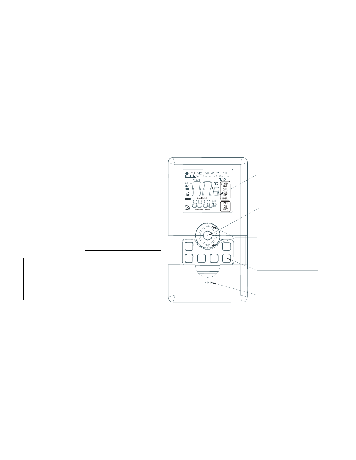
LCD Display: Shows
time, day, temperature,
information as required.
functions.
time, program, and configuration
and decreasing selections in the
setting. Also used for increasing
change the temperature
Up and Down Key: Press to
and functions buttons. (see page 3)
Soft touch programming
to open, exposing buttons.
Front Cover: Slide cover down
Press to activate temporary economy
“PE”function (see page 39).

______________________________________________________WTS32 Wireless Thermostat
950-0160revB February 2, 2012
2
LCD Display
Days of Week
Period Running
Compressor Delay
Cooling On
Heating On
AUX On
Filter Change
Recovery
Setpoint Temperature
Keypad Lock
Battery Charge State
Overrides Program For Set Period
Overrides Program Until Reset
Mode System Is Running In
Mode Fan Is Running In
Clock
Setpoint / Room Temperature
°C indication
°F indication
Displays When Transmitting
LCD Display
Heat or Cool During Programming
HEAT
COOL
Wait
Cool On
AUX
Heat On
FILTER
AM
Room Temperature
______________________________________________________WTS32 Wireless Thermostat
950-0160revB February 2, 2012
3
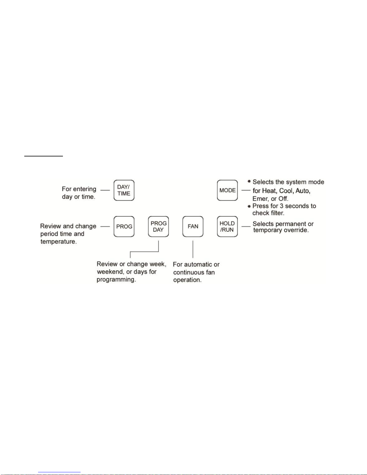
Key Functions
______________________________________________________WTS32 Wireless Thermostat
950-0160revB February 2, 2012
4
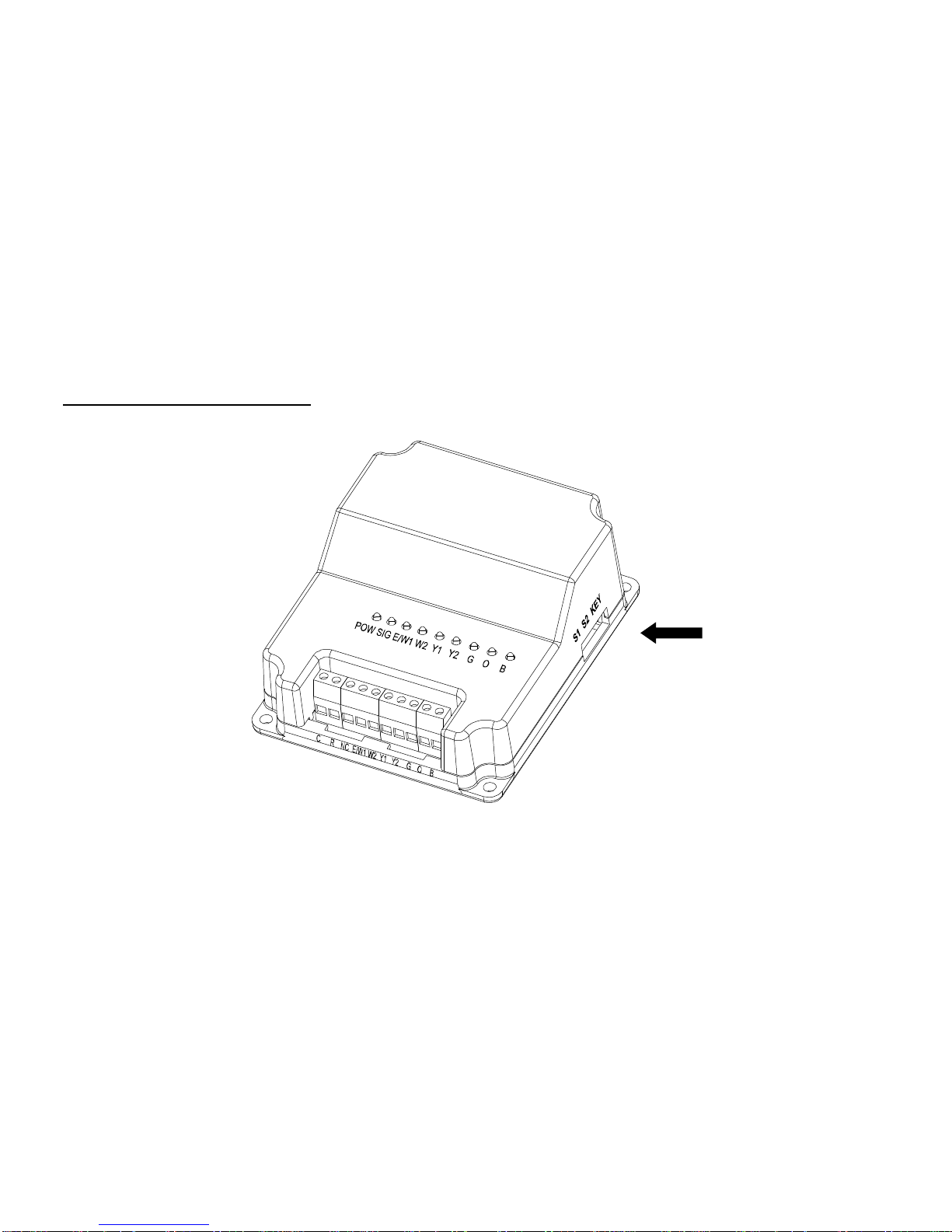
Receiver (controller) Model 4350016
•Press to match to thermostat. SIG
LED will illuminate. When signal is
received from thermostat SIG LED will
flash then turn off. Other LEDs will
illuminate when signal is received from
thermostat.
•Outdoor sensor terminals.
•Outdoor sensor part number 4350012.

______________________________________________________WTS32 Wireless Thermostat
950-0160revB February 2, 2012
5
Features
Programming (armchair): 5+2, 5+1+1 or 7 day.
Programmable or non-programmable (selectable).
Temperature range: Heating 41˚F to 95˚F / Cooling 45˚F to 99˚F.
Thermostat power: Lithium battery (USB charging cable included).
Real time clock: 12 or 24 hours.
System selection (up to 3 heat / 2 cool).
˚F or ˚C selectable.
Intelligent recovery.
Differential selection.
Compressor delay.
Auto changeover.
Transmits up to 300 feet.
Low battery warning.
Filter reminder.
Program override (hold).
Keypad lock.
Backlight (selectable on or off).
Table stand.
Quick wall mount (removable).
Temporary economy setting.
Key pad lock out.
Outdoor compressor lock out (use sensor P/N 435-0012) .

______________________________________________________WTS32 Wireless Thermostat
950-0160revB February 2, 2012
6
Systems
Conventional System
Heat only
Cool only
1 stage cooling / 1 stage heating
2 stage cooling / 2 stage heating
Heat Pump System
1 stage cooling / 2 stage heating
2 stage cooling / 3 stage heating

______________________________________________________WTS32 Wireless Thermostat
950-0160revB February 2, 2012
7
Heat Pump (No Aux. or Emergency Heat)
Yes
Heat Pump (with Aux. or Emergency Heat)
Yes
Standard Heat & Cooling Systems
Yes
Two Stage Heat & Two Stage Cool
Yes
Standard Heat Only Systems
Yes
Millivolt Heat Only Systems–Floor or Wall
Furnaces
Yes
Standard Central Air Conditioning
Yes
Gas or Oil Heat
Yes
Electric Furnace
Yes
Hydronic (Hot Water) Zone Heat-2 Wires
Yes
Hydronic (Hot Water) Zone Heat–3 Wires
No
CAUTION! - This thermostat will NOT control 110/220 Volt systems.
CAUTION! - Before leaving on vacation or an extended absence, check to see if the battery is fully charged. If the
battery charge goes low enough the thermostat will cease to transmit. If the receiver does not receive a signal within 30
minutes it will turn off and there will be no heating or cooling. One solution is to leave the thermostat plugged into the
power supply (PN 4350017). Transmitter will operate while charging.
IMPORTANT! –If using a Heat Pump System with fossil fuel as AUX Heat, an external fossil fuel kit or outdoor sensor
must be installed and CONFIGURATION STEP 11 (STAGES) must be set to CO.

______________________________________________________WTS32 Wireless Thermostat
950-0160revB February 2, 2012
8
Specifications
Transmitter Technical Data (Thermostat)
Power
Lithium Battery, rechargeable
Working environment
32°F~120°F
Moisture
0~95%RH(non-condensing)
Shell
Fire retardant PC ABS
Dimension
5.31”x3.74”x0.98”in (HxWxD)
Communication interface
Wireless
Wireless carrier wave frequency
433 MHz
Communication baud rate
10 kbps
Wireless channels
1~ 6 channels
Communication distance
Beeline distance 300ft (100m) in the field (The
distance will be shorter through walls and floors.)
Note: “PE”function (see page 39)

______________________________________________________WTS32 Wireless Thermostat
950-0160revB February 2, 2012
9
Receiver Technical Data (Controller)
Power
AC24V±10%,50/60Hz
Working environment
32°F~120°F
Moisture
0~95%RH(non-condensing)
Shell
Fire retardant PC ABS
Dimension
4.5x3.8x1.8 in (HxWxD)
Connection interface
Each terminal capable of accepting 2 x 18 AWG
solid copper wires.
Wireless carrier wave frequency
433 MHz
Communication baud rate
10 kbps
Wireless channels
1~6 channels
Communication distance
Beeline distance 300ft (100m) in the field (The
distance will be shorter through walls and floors.)
______________________________________________________WTS32 Wireless Thermostat
950-0160revB February 2, 2012
10
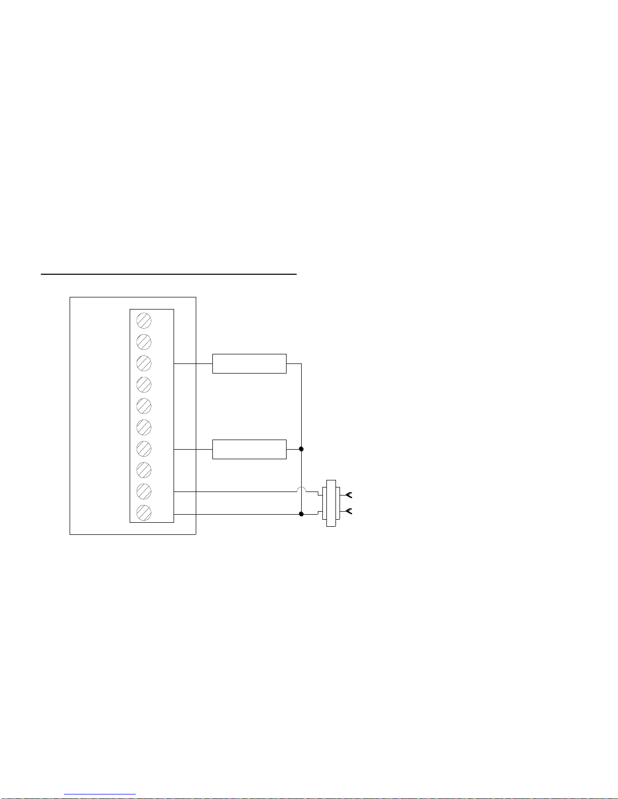
Wiring Schematics for Conventional Systems - Heat Only
Receiver
(Controller ) O
B
G
Y2
Y1
W2
E/W1
NC
R
C
HEAT RELAY
24 VAC
FAN RELAY
______________________________________________________WTS32 Wireless Thermostat
950-0160revB February 2, 2012
11
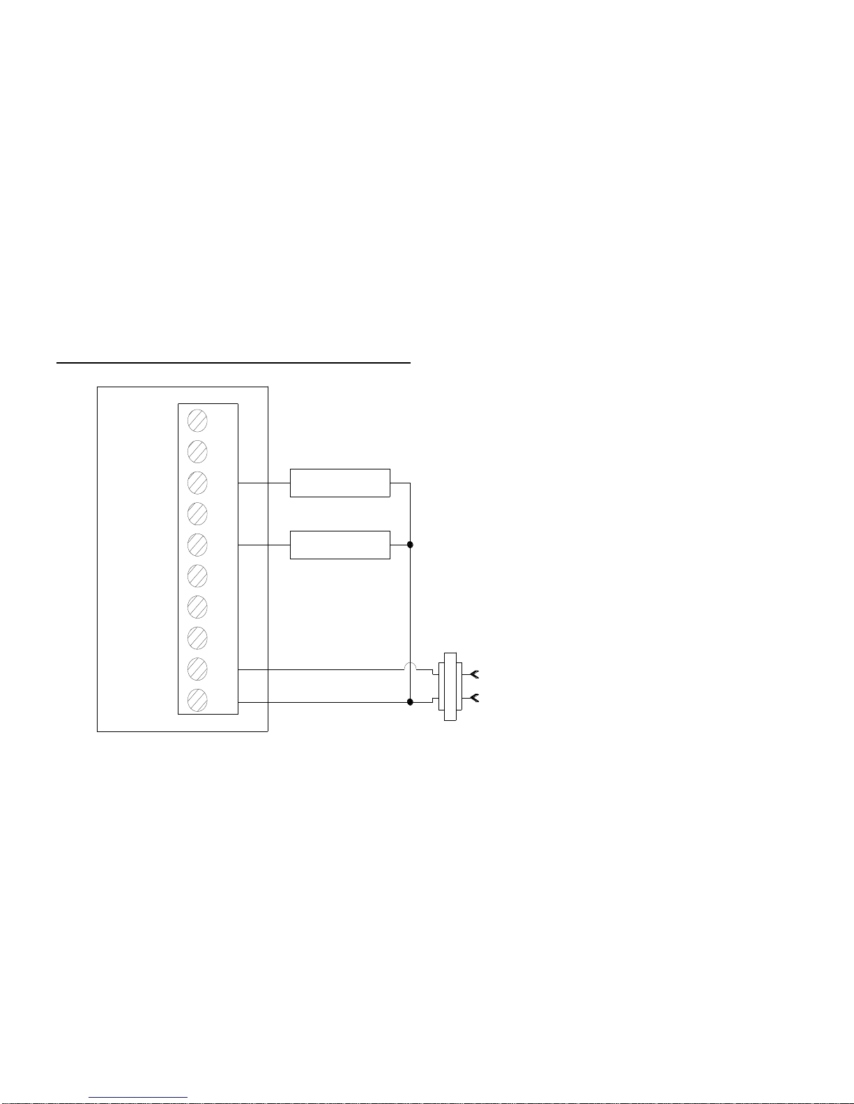
Wiring Schematics for Conventional Systems - Cool Only
COOL RELAY
Receiver
(Controller ) O
B
G
Y2
Y1
W2
E/W1
NC
R
C24 VAC
FAN RELAY
______________________________________________________WTS32 Wireless Thermostat
950-0160revB February 2, 2012
12
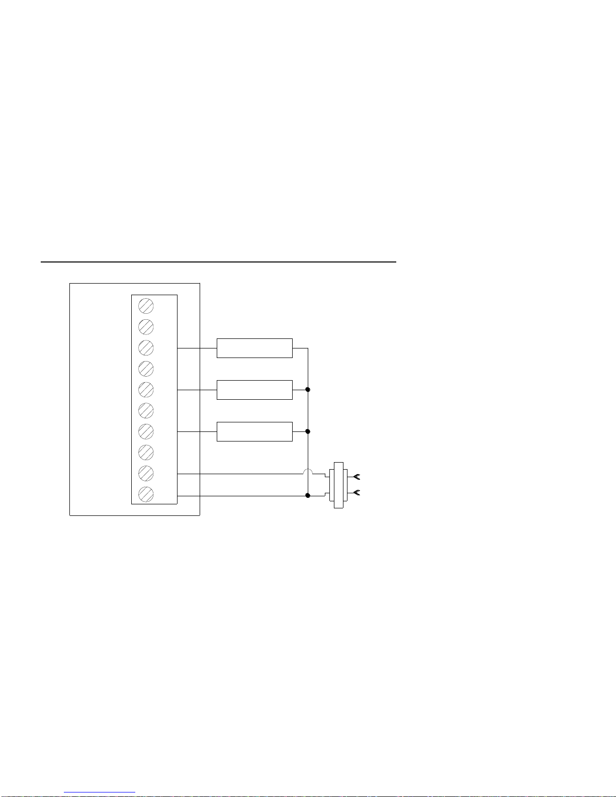
Wiring Schematics for Conventional Systems - 1 stage cooling / 1 stage heating
Receiver
(Controller ) O
B
G
Y2
Y1
W2
E/W1
NC
R
C
FAN RELAY
24 VAC
COOL RELAY
HEAT RELAY
NOTE:
When two transformers are in the system,
the smaller transformer must be eliminated
and 24 VAC power must be supplied to the
receiver. The UL approved transformer
remaining in the system must be capable of
handling both systems (cooling and heating).
______________________________________________________WTS32 Wireless Thermostat
950-0160revB February 2, 2012
13
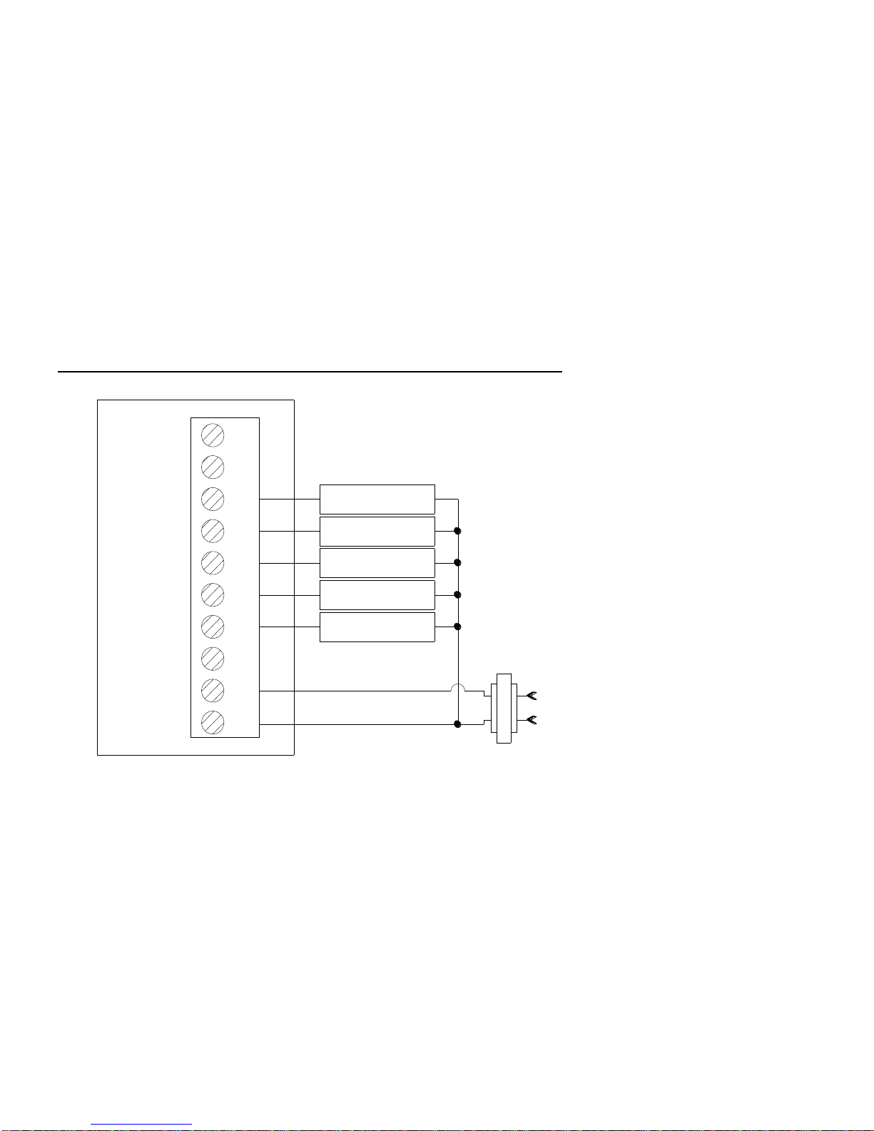
Wiring Schematics for Conventional Systems - 2 stage cooling / 2 stage heating
COOL RELAY
HEAT RELAY
COOL RELAY
HEAT RELAY
Receiver
(Controller ) O
B
G
Y2
Y1
W2
E/W1
NC
R
C
FAN RELAY
24 VAC
NOTE:
When two transformers are in the system,
the smaller transformer must be eliminated
and 24 VAC power must be supplied to the
receiver. The UL approved transformer
remaining in the system must be capable of
handling both systems (cooling and heating).

______________________________________________________WTS32 Wireless Thermostat
950-0160revB February 2, 2012
14
Wiring Schematics for Heat Pump Systems -1 stage cooling / 2 stage heating
IMPORTANT! –If using a Heat Pump
System with fossil fuel as AUX Heat,
an external fossil fuel kit or outdoor
sensor must be installed and
CONFIGURATION STEP 11
(STAGES) must be set to CO.
COMPRESSOR
EMER
HEAT(AUX )
REVERSING VALVE
S1
S2
Receiver
(Controller ) O
B
G
Y2
Y1
W2
E/W1
NC
R
C24 VAC
FAN RELAY
OUTDOOR SENSER
(P/N 435-0012)

______________________________________________________WTS32 Wireless Thermostat
950-0160revB February 2, 2012
15
Wiring Schematics for Heat Pump Systems - 2 stage cooling / 3 stage heating
IMPORTANT! –If using a Heat Pump
System with fossil fuel as AUX Heat,
an external fossil fuel kit or outdoor
sensor must be installed and
CONFIGURATION STEP 11
(STAGES) must be set to CO.
COMPRESSOR 1
EMER
HEAT(AUX )
COMPRESSOR 2
S1
S2
OUTDOOR SENSER
(P/N 435-0012)
Receiver
(Controller ) O
B
G
Y2
Y1
W2
E/W1
NC
R
C24 VAC
FAN RELAY
REVERSING VALVE

______________________________________________________WTS32 Wireless Thermostat
950-0160revB February 2, 2012
16
Installation
Charging the Thermostat
The thermostat is supplied with a replaceable lithium ion battery. The battery can be charged through a USB cable (included)
connected to a PC or an optional power supply (PN 4350017). During the charging process the battery icon will flash on and off.
With minimal usage the lithium battery will last about 12 months before it needs recharging (Lithium ion battery PN 4350018).
The lithium ion battery has a life expectancy of 8-10 years.
Note:
1) The lithium battery should be charged for 12 hours the first 3 times it is charged to properly condition the battery.
2) Transmitter will operate while charging.
3) A fully charged battery will operate for one year under normal usage.
4) “PE”function, see page 39.
CAUTION! - Before leaving on vacation or an extended absence, check to see if the battery is fully charged. If the
battery charge goes low enough the thermostat will cease to transmit. If the receiver does not receive a signal within 30
minutes it will turn off and there will be no heating or cooling.
120 VAC power
supply (PN 4350017).
Plug USB cable into
power supply to
charge battery. No
need for computer.

______________________________________________________WTS32 Wireless Thermostat
950-0160revB February 2, 2012
17
Mounting Transmitter and Receiver
Transmitter
Tools required:
Screws and wall anchors are included for mounting the thermostat.
To install the thermostat you should have the following tools and materials.
■Slotted screwdriver ■Phillips screwdriver ■Hammer ■Electric drill and 3/16”drill bit
1) Gently pry off the round metal mounting bracket on the back of the thermostat.
2) Attach the mounting bracket to the wall using the screws and wall anchors included.
3) Align the thermostat to the bracket and push together.
The transmitter can be quickly removed from the wall mount and turn to table standing.
Table of contents
Other Seabreeze Thermostat manuals


Popular Thermostat manuals by other brands

TOTALINE
TOTALINE Deluxe 1H/1C operating manual

Honeywell
Honeywell E529.RF installation guide

Siemens
Siemens BRTRF operating instructions

HAI
HAI OMNISTAT RC-122BZ installation instructions

Toptech
Toptech True Comfort IIII TT-S-955 operating manual

Horstmann
Horstmann ChannelPlus H47XL Series 2 User operating instructions


Honeywell Home
Honeywell Home FocusPRO RTH6580WF quick start guide

Siemens
Siemens RDG200KN Basic documentation

Uponor
Uponor Ecoflex Supra Standard ETN4 Installation and operation manual

Daikin
Daikin MT 180 Installation and maintenance manual

SST
SST LumiSmart 25 quick start guide

Microsol
Microsol FLT ADVANCED user manual