Seagull EP PC-9 User manual
Kit features.
• Ready-made—minimalassembly&finishingrequired.
• Ready-coveredcovering.
• Photo-illustratedstep-by-stepAssemblyManual.
MadeinVietnam.
Specifications
WingSpan-------------------------------49.6in------------------126cm.
WingArea-----------------------------454.2sqin----------29.3sqdm.
Weight-----------------------------------1.9-2.6lbs -------850-1200g.
Length------------------------------------ 37.7in-------------------95.7cm.
Radio-------------------------------4channelwith4sub-microservos.
Motorsize-------------------------------HimarkOutrunnerC3522-990.
Need to Complete
Speed Control: SJ Conquest 35 or 45 amp.
RecommendedBattery3-cell 11.1V 2200mAh to 3200mAhLi-Po.
ASSEMBLY MANUAL
MS:X8
PC9-EP.Instruction Manual.
2
INTRODUCTION.
Thank you for choosing the EP-PC9 ARTF by SEAGULL EP. The EP-PC9 was designed with the
intermediate/advancedsportflyer inmind.It isa semiscale airplane whichis easy to flyandquick
toassemble.Theairframeisconventionallybuiltusing balsa, plywood to make it stronger thanthe
averageARTF,yetthedesignallowstheaeroplanetobekeptlight.Youwillfindthatmostofthework
has been done for you already.Flying the EP-PC9 is simply a joy.
This instruction manual is designed to help you build a great flying aeroplane. Please read this
manualthoroughlybeforestartingassemblyofyour EP-PC9.Usethepartslistingbelowtoidentify
all parts.
WARNING.
Please be aware that this aeroplane is not a toy and if assembled or used incorrectly it is
capable of causing injury to people or property. WHEN YOU FLY THIS AEROPLANE YOU
ASSUME ALL RISK & RESPONSIBILITY.
If you are inexperienced with basic R/C flight we strongly recommend you contact your R/C
supplierandjoinyourlocalR/CModelFlyingClub.R/CModelFlyingClubsofferavarietyoftraining
proceduresdesignedtohelp thenewpilotonhiswaytosuccessful R/C flight.Theywillalsobeable
to advise on any insurance and safety regulations that may apply.
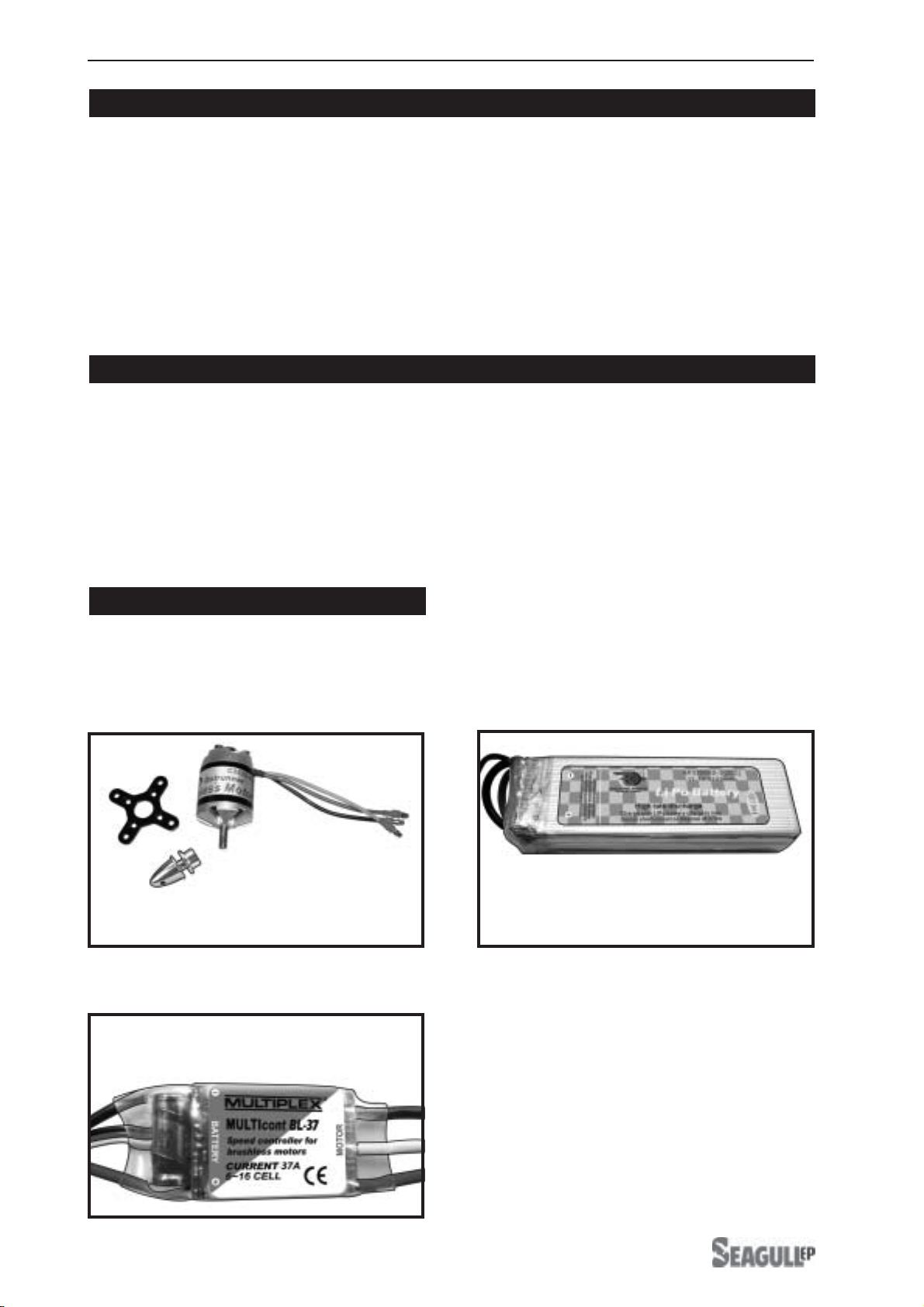
ADDITIONAL ITEMS REQUIRED.
! Motor: Himark outrunner
C3522-990
!Radio with four sub-micro servos.! Speed control: 35A to 45A.
!Battery: Awesome Power battery
11.1V 2200 mAh - 11.1V 3200 mAh.
Himark outrunner
C3522-990.
Speed control:
SJ Conquest 35 or 45 amp.
Awesome Power battery
11.1V 2200 mAh - 11.1V 3200 mAh.
www.seagullmodels.com
3
NOTE: To avoid scratching your new aero-
planewesuggestthatyoucoveryour
workbench with an old towel. Keep a
couple of jars or bowls handy to hold
the small parts after you open the
bags.
Pleasetrialfitallparts.Makesureyou
have the correct parts and that they
fit and are aligned properly before
gluing! This will ensure proper as-
sembly as the EP PC9 is made from
natural materials and minor adjust-
ments may have to be made.
The paint and plastic parts used in
this kit are fuel proof. However, they
arenottolerantofmanyharshchemi-
cals including the following: paint
thinner, cyano-acrylate glue accel-
erator,cyanoacrylategluede-bonder
andacetone.Donotletthesechemi-
calscome in contact with the colours
onthecoveringandtheplasticparts.
TOOLS & SUPPLIES NEEDED.
!Thick cyanoacrylate glue.
!30 minute epoxy.
!5 minute epoxy.
!Hand or electric drill.
!Assorted drill bits.
!Modellingknife.
!Straight edge ruler.
!2mm ball driver.
!Phillips head screwdriver.
!220 grit sandpaper.
!90° square or builder’s triangle.
!Wire cutters.
!Masking tape & T-pins.
!Thread-lock.
!Paper towels.
Please contact Horizon Hobby for product support and technical assistance at 877-
504-0233. ReplacementpartsareavailablefromyourlocaldealerorthroughHorizon
Hobby.
HORIZON HOBBY DISTRIBUTIONS INC
4105FieldstoneRd, Champaign, IL 61822- USA
FOR USA MARKET ONLY.
Horizon Hobby, Inc. guarantees this kit to be free from defects in both material and workmanship
at the date of purchase. This warranty does not cover any parts damage by use or modification.
In no case shall Horizon Hobby’s liability exceed the original cost of the purchased kit. Further,
Horizon Hobby reserves the right to change or modify this warranty without notice. In that
Horizon Hobby has no control over the final assembly or material used for the final assembly,
no liability shall be assumed nor accepted for any damage resulting from the use by the user
of the final user-assembled product. By the act of using the user-assembled product, the user
accepts all resulting liability.
Once assembly of the model has been started, you must contact Horizon Hobby, Inc. directly
regarding any warranty question that you have. Please do not contact your local hobby shop
regarding warranty issues, even if that is where you purchased it. This will enable Horizon to
better answer your questions and service you in the event that you may need any assistance.
If the buyer is not prepared to accept the liability associated with the use of this product, the
buyer is advised to return this kit immediately in new and unused condition to the place of
purchase.
Horizon Hobby
4105 Fieldstone Road
Champaign, Illinois 61822
(217)355-9511
PC9-EP.Instruction Manual.
4
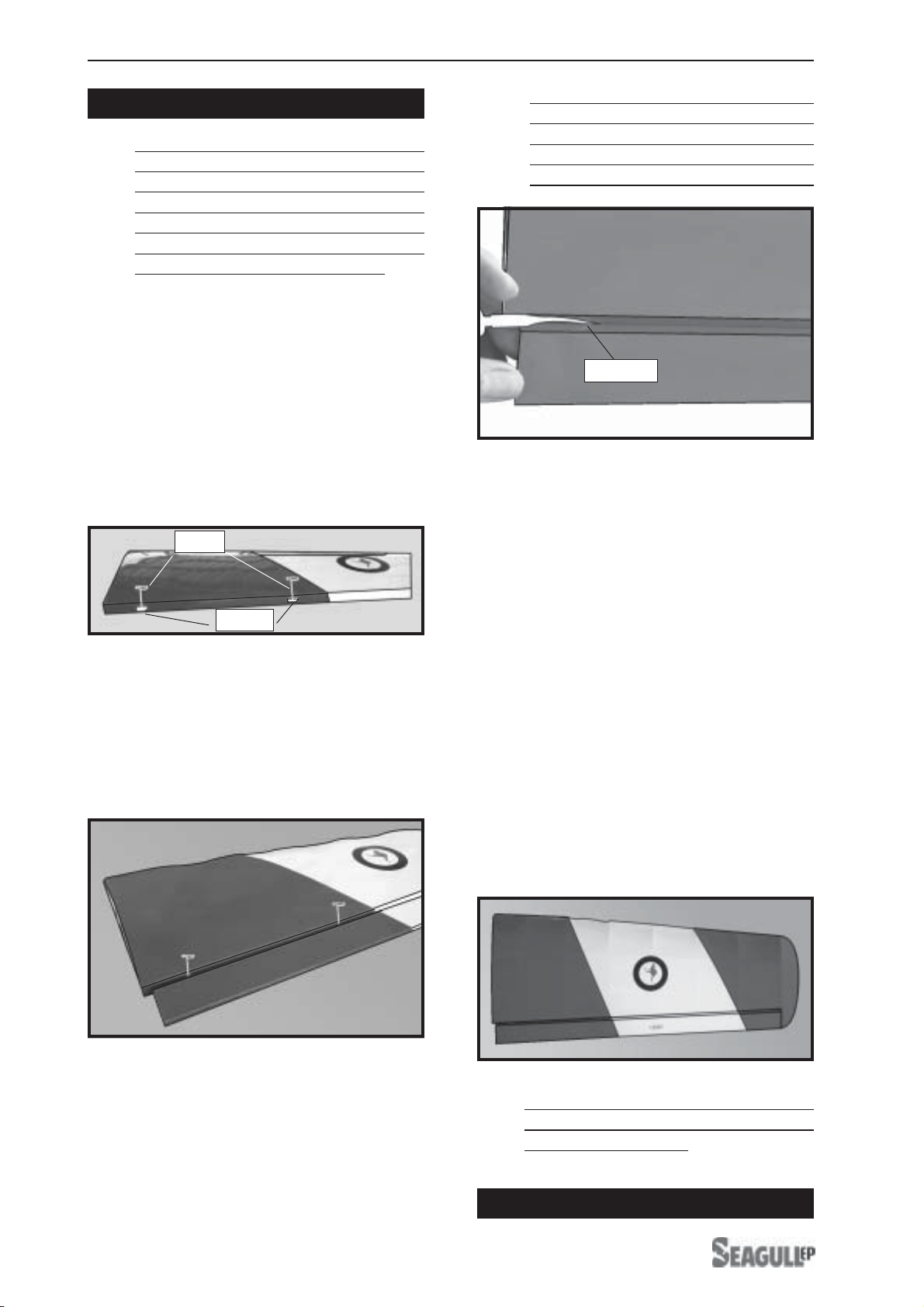
!1) Carefully remove the aileron from one
of the wing panels. Note the position of the
hinges.
!2)Removeeachhingefromthe wing panel
and aileron and place a T-pin in the center of
each hinge. Slide each hinge into the wing
panel until the T-pin is snug against the wing
panel. This will help ensure an equal amount
ofhingeisoneithersideofthehingelinewhen
the aileron is mounted to the aileron.
HINGING THE AILERONS.
!3) Slide the wing panel on the aileron until
there is only a slight gap. The hinge is now
centered on the wing panel and aileron.
Remove the T-pins and snug the aileron
against the wing panel.A gap of 1/64” or less
shouldbemaintained between thewing panel
andaileron.
!4)Deflect the aileron and completely
saturate each hinge with thin C/A glue. The
aileronsfrontsurfaceshouldlightlycontactthe
wing during this procedure. Ideally, when the
!7) Repeat this process with the other wing
panel, securely hinging the aileron in place.
!5)Turnthe wingpanel over and deflectthe
aileron in the opposite direction from the
opposite side. Apply thin C/A glue to each
hinge,makingsure thattheC/Apenetratesinto
both the aileron and wing panel.
!6) Using C/A remover/debonder and a
papertowel,remove any excess C/Agluethat
may have accumulated on the wing or in the
aileronhinge area.
hinges are glued in place, a 1/64” gap or less
will be maintained throughout the lengh of the
aileron to the wing panel hinge line. HINGING THE ELEVATOR.
!8)Afterboth ailerons are securely hinged,
firmly grasp the wing panel and aileron to
make sure the hinges are securely glued and
cannot be pulled out. Do this by carefully
applying medium pressure, trying to separate
the aileron from the wing panel. Use caution
not to crush the wing structure.
The control surfaces, including the
ailerons, elevators, and rudder, are
prehinged with hinges installed, but the
hinges are not glued in place. It is
imperativethat you properlyadhere the
hingesin place perthe steps thatfollow
using a high-quality thin C/A glue.
Note:
The hinge is constructed of a special
material that allows the C/A to wick or
penetrateanddistributethroughoutthe
hinge, securely bonding it to the wood
structureofthe wing panelandaileron.
Note:
Work the aileron up and down several
times to “work in” the hinges and check
for proper movement.
Note:
T-pin.
Hinge.
C/Aglue.
www.seagullmodels.com
5
Glue the elevator hinges in place using the
same tectniques used to hinge the ailerons.
HINGING THE RUDDER.
Glue the rudder hinges in place using the
same tectniques used to hinge the ailerons.
3x10mm.
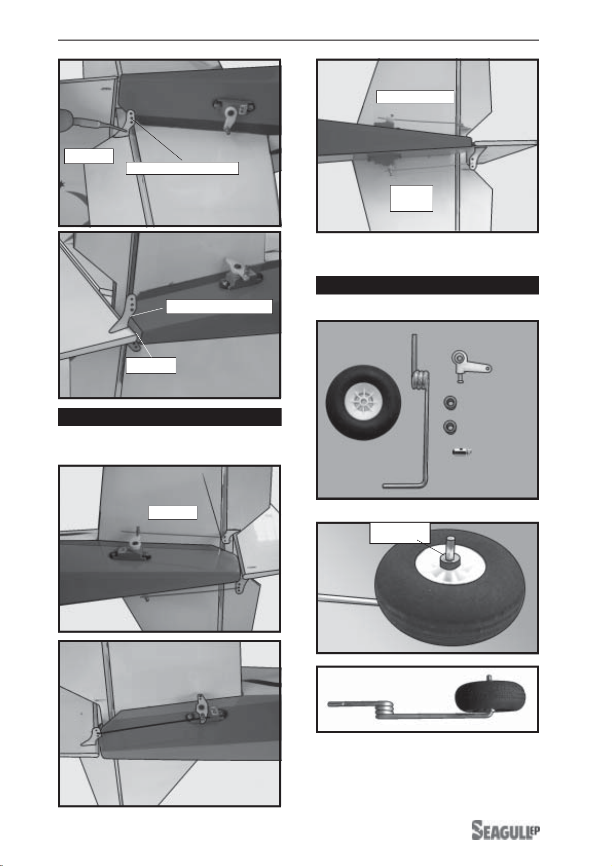
INSTALLING THE MAIN GEAR WIRES.
Assemble and mounting the wheel as
shown in the following pictures.
!2) Using a modeling knife, remove the
covering from over the two main gear mount-
ing slots located in the bottom of the wing.
!3) Insert the 90º bend of one main gear
wire into the predrilled hole in one mounting
slot.
!4) The landing gear wire is held in place
using two nylon landing gear straps and four
2mm x 12mm wood screws.
Gear mounting slot.
Wing bottom.
Landing gear wire.
Landinggear.
Plywood coloa.
C/a glue
AILERON SERVOS-LINKAGES.
! 1) Install the metal connector onto servo
arm as same as picture below.
!2) Turn the wing panel right side up. Using
amodelingknife,removethecovering at servo
tray.
Attach the thread to the servo lead and
carefully thread it though the wing.
! 3)Secure the servos with the screws pro-
vided with your radio system.
!6) Reinstall the gear wire and install the
straps using the four 2 x 12mm wood screws.
Tighten the screws completely to secure the
gear wire in place.
Install the rubber grommets and brass collets
onto the aileron servo. Test fit the servo into
the aileron servo mount.
Attach the micro control connector to the
servo arms. Be sure to use the lock tie but it
could free rotation .
Lock tie.
! 4) Insert aileroncontrolhorn to the aileron.
as same as picture below.
2 x 12mm.
Landing gear wire.
Because the size of servos differ, you
mayneedto adjustthesizeoftheprecutopen-
ing in the mount. The notch in the sides of
themountallowtheservoleadtopassthrough.
Control horn.
Wing bottom.
Aileroncontrolhorn slot.
Control horn.
Because the size of servos differ, you
mayneedtoadjustthesizeoftheprecutopen-
ing in the mount. The notch in the sides of the
mount allow the servo lead to pass through.
Pushrod wire.
Control horn.
Repeat the procedure for orther wing
haft.
!1) Locate and cut out the covering film
fromthe servo holes inboth sides offuselage.
FUSELAGE SERVO INSTALLATION.
INSTALLING THE SWITCH.
Installtheswitch into the precutholein the
side, in the fuselage.
!3)Secure the servoswith the screws pro-
vided with your radio system.
!2) Installthe rubber grommetsand brass
collets onto the elevator servo. Test fit the
servo into the elevator servo mount.
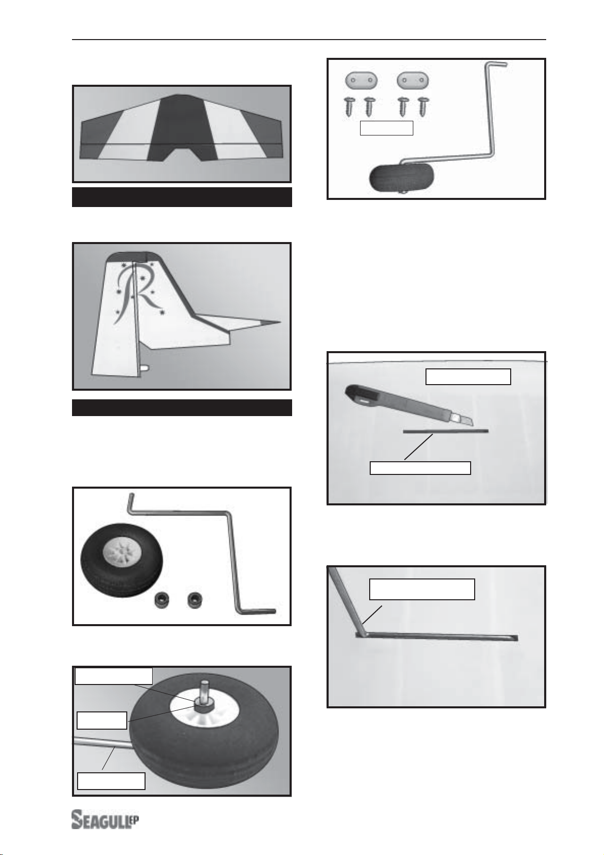
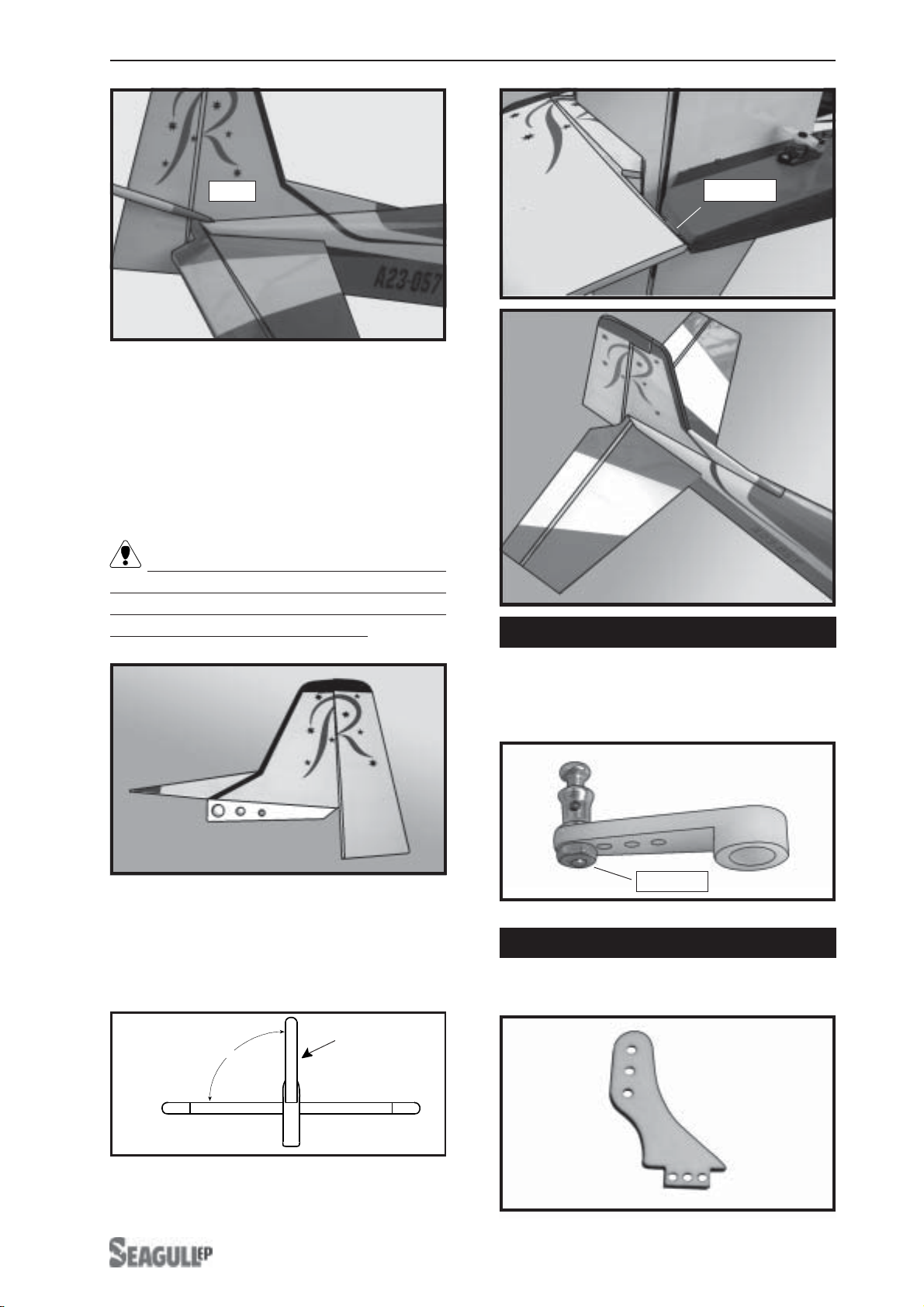
HORIZONTALSTABILIZER.
!1) Using a ruler and a pen, locate the
centerlineofthehorizontalstabilizer,atthetrail-
ing edge, and place a mark. Use a triangle
and extend this mark, from back to front,
across the top of the stabilizer. Also extend
thismark down theback of thetrailing edge of
the stabilizer.
C/Aglue.
Control horn.
!2)Usinga modelingknife,carefullyremove
thecoveringatmounting slot of horizontalsta-
bilizer ( both side of fuselage).
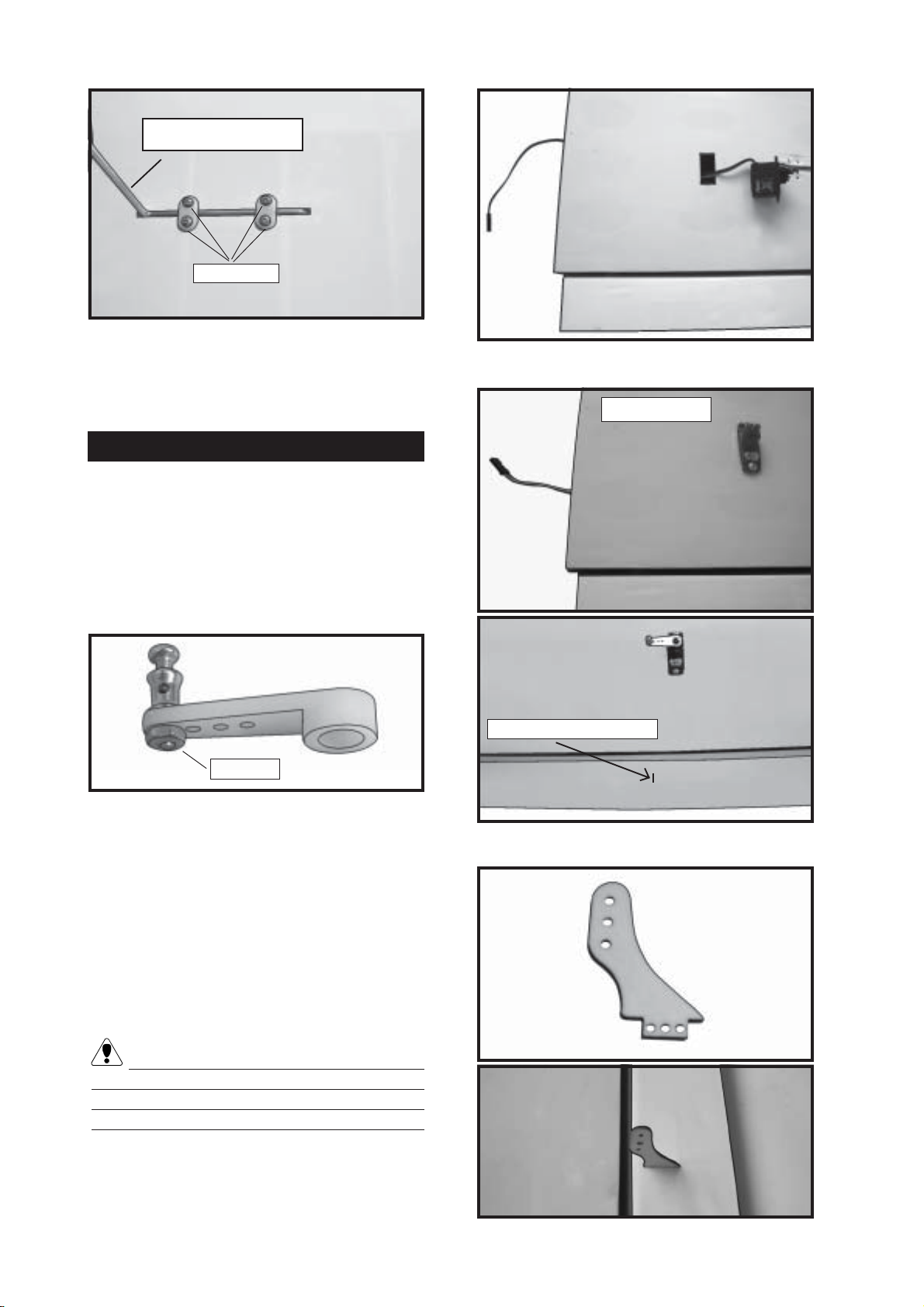
! 3) Slide the stabilizer into place in the pre-
cut slot in the rear of the fuselage. The stabi-
lizer should be pushed firmly against the front
of the slot.
Rightside.
Remove covering.
Elevator servo.
Rightside.
Center line.
Left side.
Rudder servo.
Switch.
PC9-EP.Instruction Manual.
8
!1) Using a modeling knife, remove the
covering from over the precut hinge slot cut
intothelowerrearportionofthefuselage. This
slot accepts the lower rudder hinge.
!3) While holding the vertical stabilizer
firmly in place, use a pen and draw a line on
each side of the vertical stabilizer where it
meets the top of the fuselage.
!2) Slidethe vertical stabilizerinto the slot
in the top of the fuselage. The rear edge of
thestabilizer shouldbeflushwiththerearedge
of the fuselage and the lower rudder hinge
should engage the precut hinge slot in the
lowerfuselage. The bottom edgeof the stabi-
lizer should also be firmly pushed against the
top of the horizontal stabilizer.
! 4) With the stabilizer held firmly in place,
use a pen and draw lines onto the stabilizer
where it and the fuselage sides meet. Do this
on both the right and left sides and top and
bottom of the stabilizer.
! 5) Remove the stabilizer. Using the lines
youjust drew asa guide, carefullyremove the
covering from between them using a model-
ingknife.
! 6) When you are sure that everything is
alignedcorrectly,apply C/Aglueto the top and
bottom of the stabilizer mounting area and to
the stabilizer mounting platform sides.
VERTICAL STABILIZER INSTALLATION.
When cuttingthrough the coveringto re-
moveit, cut with only enough pressure to only
cut through the covering itself. Cutting into
the balsa structure may weaken it.
Pen.
Removecovering. Hingeslot.
Hinge.
www.seagullmodels.com
9
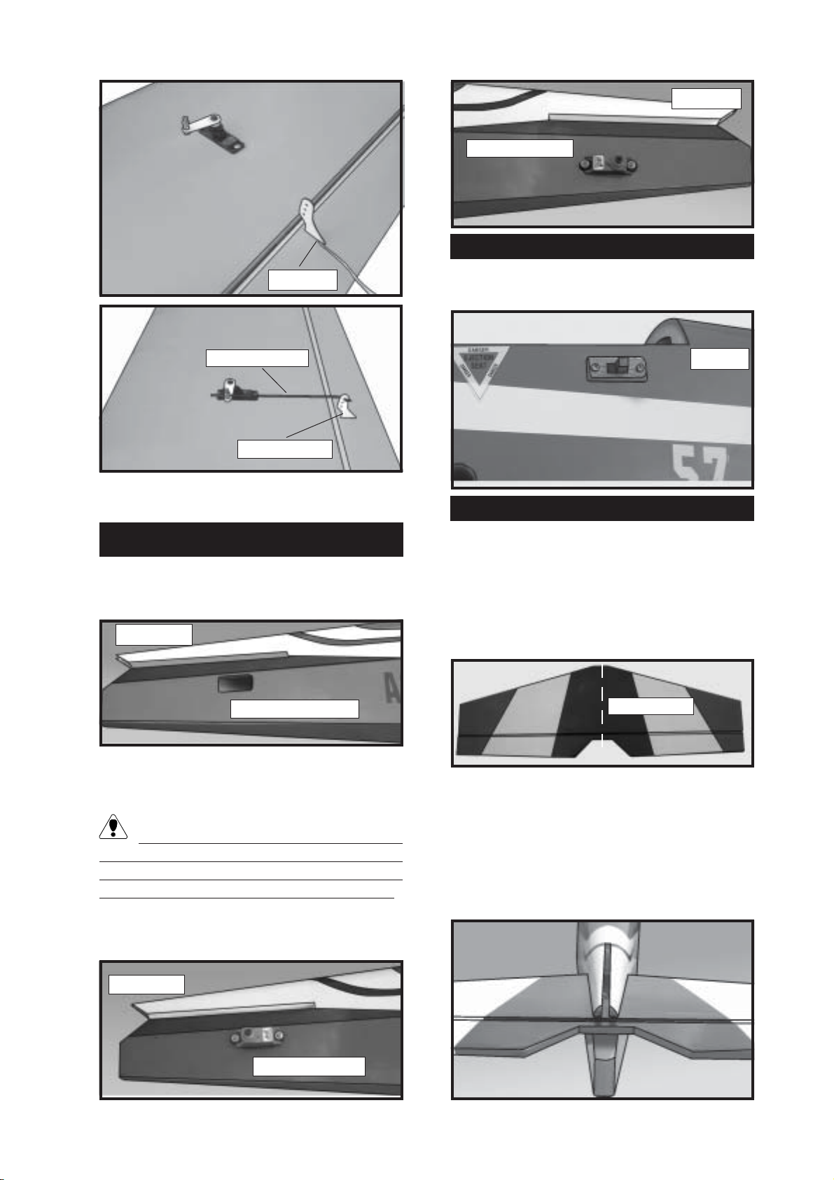
!5) Slide the vertical stabilizer back in
place. Using a triangle, check to ensure that
thevertical stabilizer isaligned 90º tothe hori-
zontal stabilizer.
90º
Vertical
Stabilizer.
Horizontal
Stabilizer.
!4) Remove the stabilizer. Using a mod-
eling knife, remove the covering from below
the lines you drew. Also remove the covering
from the bottom edge of the stabilizer and the
bottomandtopedgesofthefillerblock. Leave
the covering in place on the sides of the filler
block.
When cutting through the covering to re-
moveit, cutwith only enough pressure to only
cut through the covering itself. Cutting into
the balsa structure may weaken it.
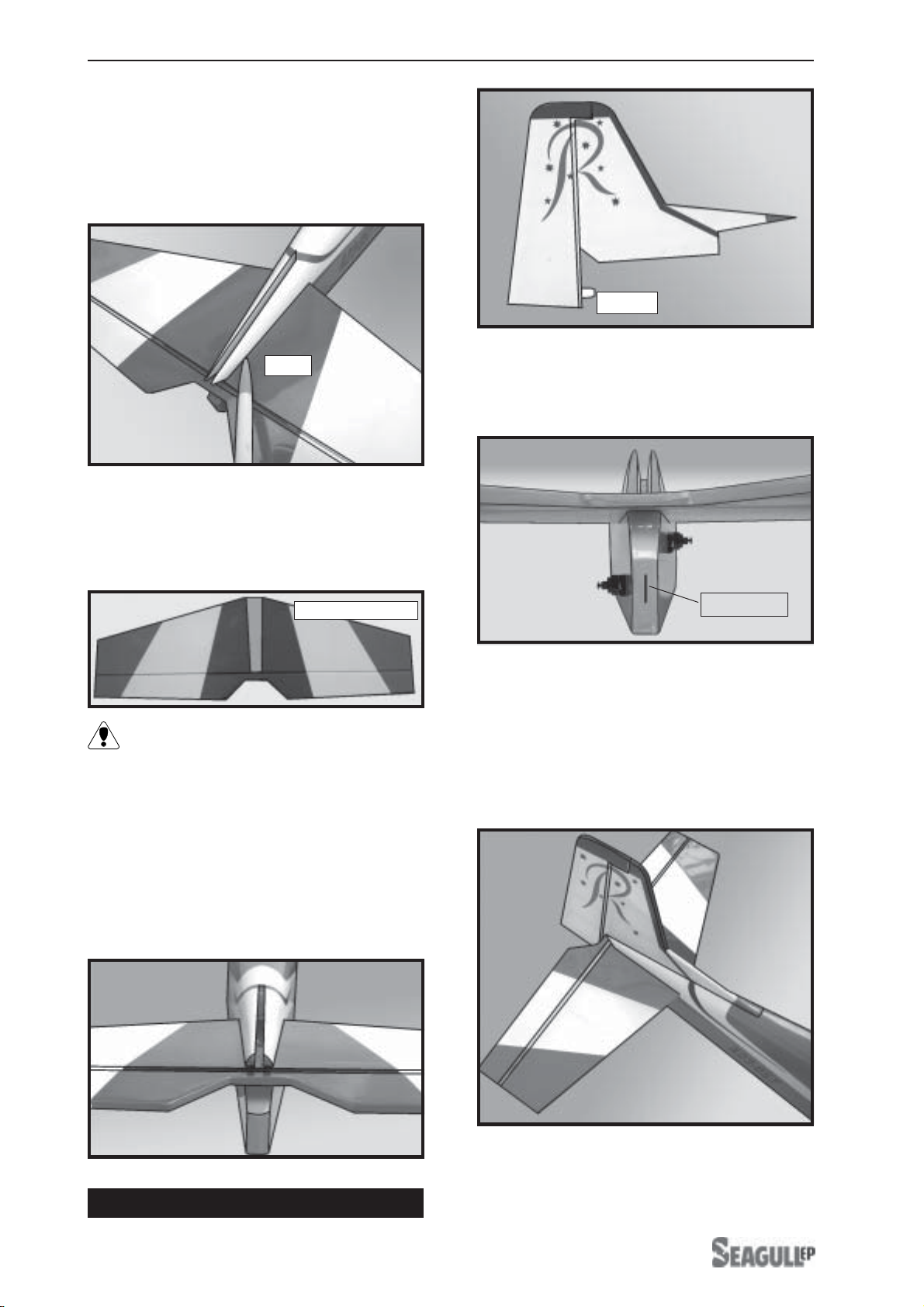
! 6) When you are sure that everything is
aligned correctly, apply C/Aglue to fix them.
Attach the micro control connector to the
servo arms. Be sure to use the lock tie but it
could free rotation .
SERVO ARM INSTALLATION.
Lock tie.
Control horn install as same as method of
aileron wing. See pictures below.
CONTROL HORN INSTALLATION.
Pen.
Removecovering.
C/Aglue.
PC9-EP.Instruction Manual.
10
Pushrod install as same as method of
pushrod wing. See pictures below.
PUSHROD INSTALLATION.
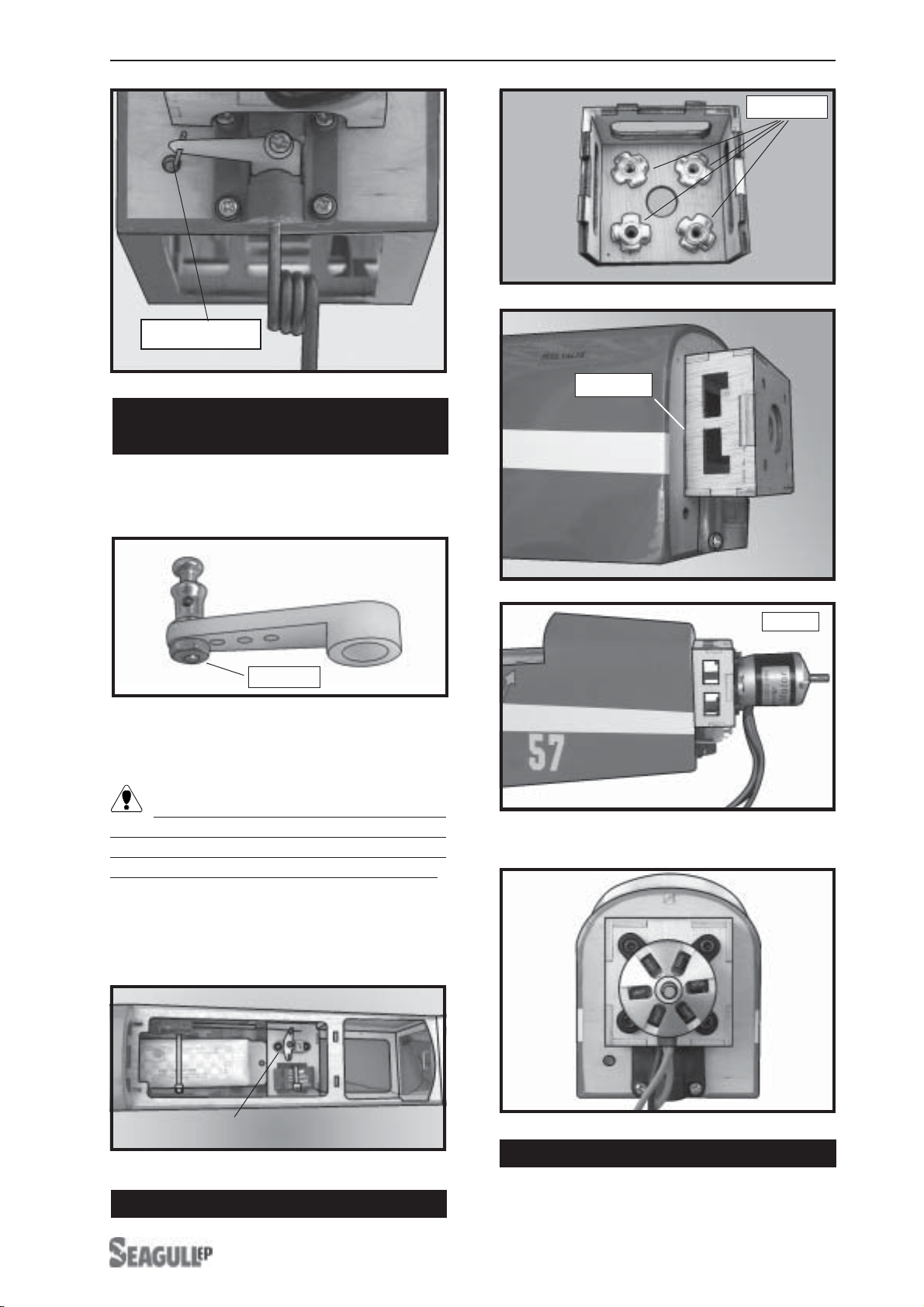
NOSE GEAR INSTALLATION.
Adjust the nose gear steering arm until the
arm is parallel with the fire wall.
Install the pushrod wire as shown.
C/Aglue. Elevator control horn.
Pushrod. C/a glue
Elevator servo.
Rudder
servo.
C/Aglue.
Rudder control horn.
www.seagullmodels.com
11
INSTALLING THE STEERING ARM
SERVO.
Lock tie.
Attach the micro control connector to the
servo arms. Be sure to use the lock tie but it
could free rotation .
!1) Installthe rubber grommetsand brass
collets onto the stearing servo. Test fit the
servo into the stearing servo mount.
!2)Secure the servoswith the screws pro-
vided with your radio system.
Because the size of servos differ, you
mayneedtoadjustthesizeoftheprecutopen-
ing in the mount. The notch in the sides of the
mount allow the servo lead to pass through.
INSTALLING ELECTRIC MOTOR.
Blindnut.
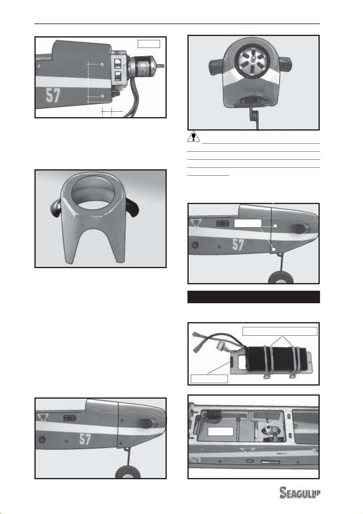
COWLING INSTALLATION.
!1) Using a pen to mark the points follow-
ing the instruction below.
pushrod wire
C/Aglue.
Motor.
Stearing servo.
PC9-EP.Instruction Manual.
12
!4) Slide the cowl back over the motor.
!2) Slide the fiberglass cowl over the en-
gineandlineupthe back edge of thecowlwith
themarks you madeon the fuselagethen trim
and cut.
INSTALLING THE BATTERY-RECEIVER.
See pictures below.
Battery tray
Tie wrap or rubber band.
The propeller should not touch any part
of the spinner cone. If it does, use a sharp
modeling knife and carefully trim away the
spinner cone where the propeller comes in
contact with it.
!3) While keeping the back edge of the
cowl flush with the marks, align the front of
thecowl with the crankshaftof the motor. The
front of the cowl should be positioned so the
crankshaft is in nearly the middle of the cowl
opening.Usethe spinner backplateasaguide.
Hold the cowl firmly in place using pieces of
masking tape.
!5) Secure the cowl with the screw pro-
vide with hardware.
Motor.
5.2cm
0.8cm
1cm
2x8mm.
Battery.

www.seagullmodels.com
13
Insert two wing panels as pictures below:
ATTACHMENT WING-FUSELAGE.
Attach the aluminium tube into fuselage.
!1) It is critical that your airplane be bal-
anced correctly. Improper balance will cause
yourplanetolose control and crash. Thecen-
ter of gravity is locate 5.5-6.5cm back from
theleadingedge ofthewing,measuredatwing
tip.
BALANCING.
!2) If the nose of the plane falls, the plane
is nose heavy. To correct this first move the
battery pack further back in the fuselage. If
this is not possible or does not correct it, stick
small amounts of lead weight on the fuselage
sides under the horizontal stabilizer. If the tail
of the plane falls, the plane is tail heavy. To
correctthis,movethe battery and receiverfor-
ward orif this is not possible, stick weight onto
the firewall. When balanced correctly, the air-
plane should sit level or slightly nose down
when you lift it up with your fingers.
!1) We highly recommend setting up the
EP-PC9 using the control throws listed atright.
We have listed control throws for both Low
Rate (initial test flying/sport flying) and High
Rate (aerobatic flying).
CONTROL THROWS.
INITIAL FLYING/SPORT FLYING
Ailerons: 3/8” up 3/8” down
Elevator: 3/8 ” up 3/8” down
Rudder: 1/2” right 1/2” left
AEROBATIC FLYING
Ailerons: 1/2”up 1/2”down
Elevator: 5/8”up 5/8” down
Rudder: 1” right 1”left
Do not use the aerobatic settings for
initial test flying or sport flying.
! 3) When the elevator, rudder and aileron
control surfaces are centered, use a ruler and
check the amount of the control throw in each
surface. The control throws should be
measured at the widest point of each sur-
face!
!2) Turn on the radio system,and with the
trim tabs on the transmitter in neutral, center
the control surfaces by making adjustments
totheclevisesoradjustableservoconnectors.
The servo arms should be centered also.
! 4) By moving the position of the adjust-
able control horn out from the control surface,
you will decrease the amount of throw of that
control surface. Moving the adjustable con-
trol horn toward the control surface will in-
crease the amount of throw.

PC9-EP.Instruction Manual.
14
FLIGHT PREPARATION.
! A) Check the operation and direction of
the elevator, rudder, ailerons and throttle.
! B) Plug in your radio system per the
manufacturer's instructions and turn every-
thingon.
! E)Check the throttle.
! D) Check the rudder. Looking from be-
hindthe airplane,move therudder stickto the
right. Theruddershouldmove to the right. If it
does not, flip the servo reversing switch on
your transmitter to change the direction.
! C) Check the elevator first. Pull back on
theelevator stick. The elevatorhalves should
move up. If it they do not, flip the servo re-
versing switch on your transmitter to change
the direction.
! F) From behind the airplane, look at the
aileronontherightwinghalf. Movetheaileron
sticktotheright. The right aileronshouldmove
upandthe other aileron shouldmovedown. If
it does not, flip the servo reversing switch on
your transmitter to change the direction.
!5) If your radio transmitter is equipped
withdualrate switches doublecheck that they
are on the low rate setting for your first few
flights.
!6) Check to ensure the control surfaces
are moving the proper amount for both low
and high rate settings.
!8) Properly balancethe propeller. Anout
of balance propeller will cause excessive vi-
bration which could lead to engine and/or air-
frame failure.
We wish you many safe and enjoyable
flights with your EP-PC9.
!7) Check the receiver antenna. It should
be fully extended and not coiled up inside the
fuselage.
PREFLIGHT CHECK.
!1) Completely charge your transmitter
and receiver batteries before your first day of
flying.
!2) Check every bolt and every glue joint
intheEP-PC9 to ensure that everything is tight
and well bonded.
!3) Double check the balance of the air-
plane. Do this with the fuel tank empty.
!4) Check thecontrol surfaces. All should
move in the correct direction and not bind in
any way.
Table of contents
Other Seagull EP Toy manuals

Popular Toy manuals by other brands

GREAT PLANES
GREAT PLANES Spirit 100 Instruction book

JAWBONES
JAWBONES The Buildable Art System Assembly instructions

Huffy
Huffy BOLTZ owner's manual

Redcat Racing
Redcat Racing Caldera XB 10E instruction manual

Nine Eagles
Nine Eagles NE C 210A instruction manual

Canon
Canon Creative Park Church of the Transfiguration Assembly instructions


 manual")
