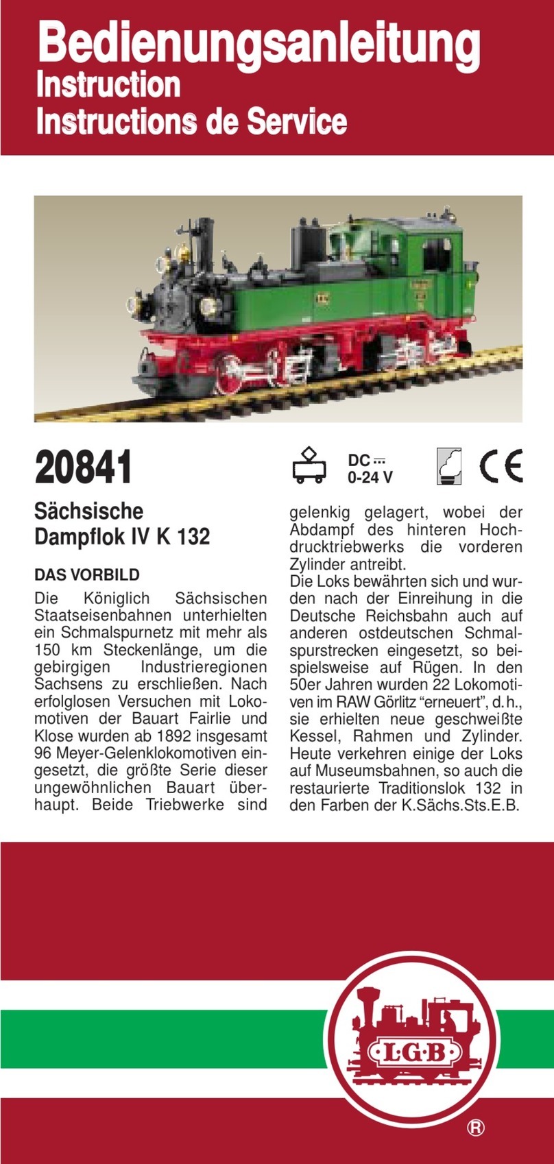
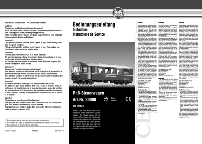
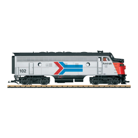
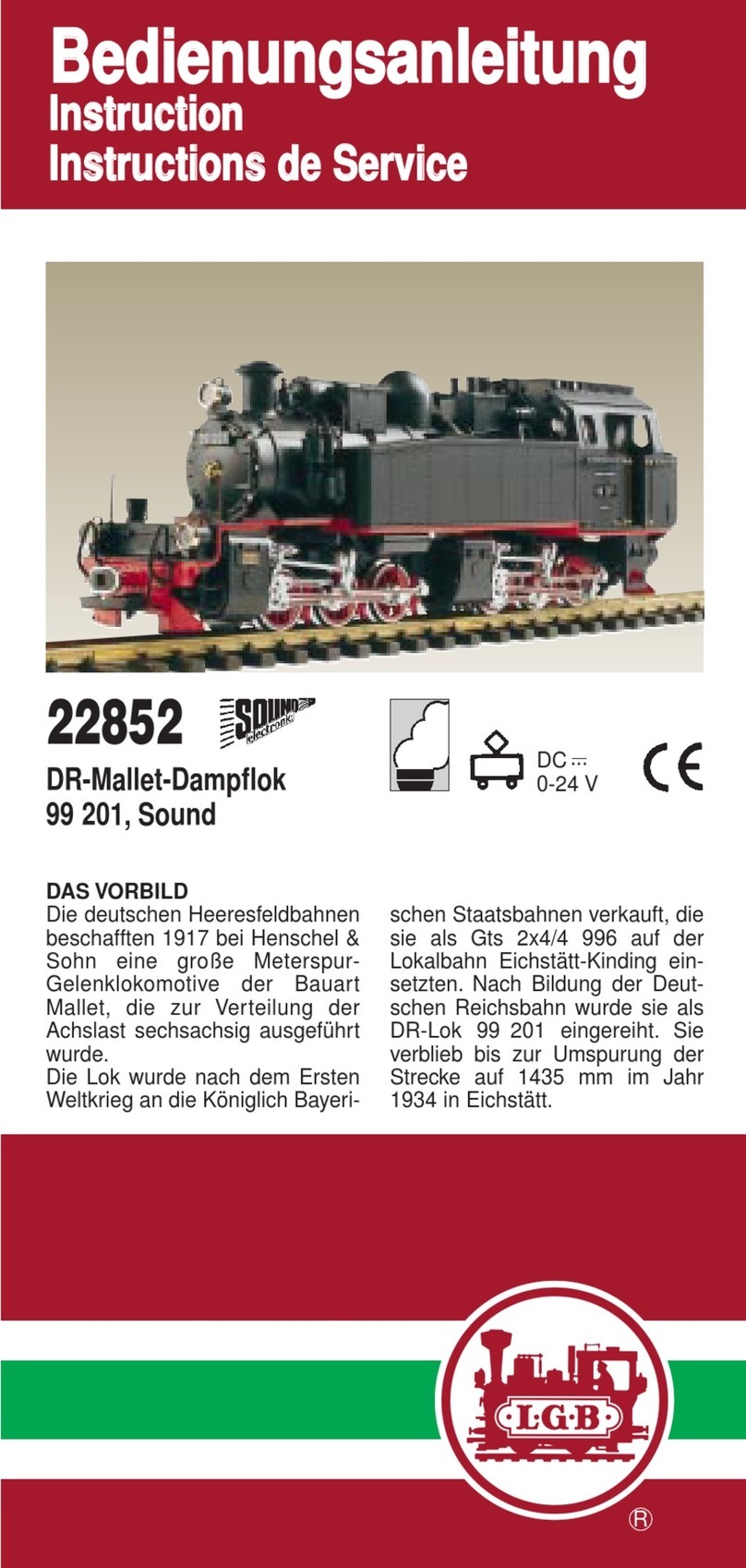
LGB Stainz 72308 User manual

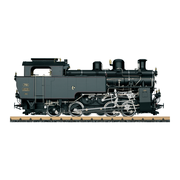
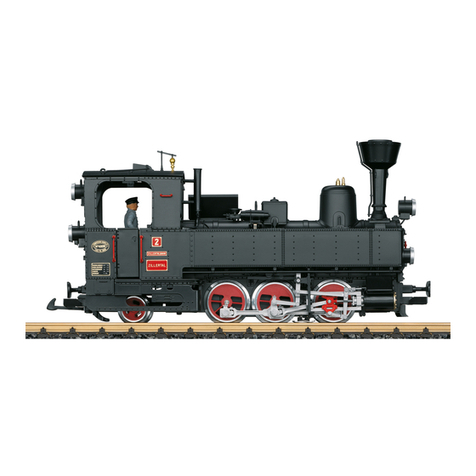
Model of the „Stainz“ steam locomotive
72308
CAUTION - ELECTRIC TRAIN
N0T RECOMMENDED FOR CHILDREN UNDER 15 YEARS OF AGE. AS
WITH ALL ELECTRIC PRODUCTS; PRECAUTIONS SHOULD BE OBSER-
VED DURING HANDLING AND USE TO PREVENT ELECTRIC SHOCK.
TRANSFORMER RATINGS-INPUT: 120 VAC, 60 HZ:
OUTPUT: SEE SIDE PANEL

2

3
Table of Contents: Page
Safety Notes 4
Important Notes 4
Functions 4
Information about operation 4
Service and maintenance 5
Figures 12
Spare parts 13
Indice del contenuto: Pagina
Avvertenze per la sicurezza 10
Avvertenze importanti 10
Funzioni 10
Avvertenze per ilfunzionamento 10
Manutenzione ed assistere 11
Figures 12
Pezzi di ricambio 13
Sommaire : Page
Remarques importantes sur la sécurité 6
Information importante 6
Fonctionnement 6
Remarques sur l’exploitation 6
Entretien et maintien 7
Images 12
Pièces de rechange 13
Indice de contenido: Página
Aviso de seguridad 8
Notas importantes 8
Funciones 8
Instrucciones de uso 8
El mantenimiento 9
Figuras 12
Recambios 13

4
Safety Notes
• This model may only be used with the operating system designed for it.
• Use only switched mode power supply units and transformers that are designed
for your local power system.
• This locomotive must never be supplied with power from more than one power pack.
• Pay close attention to the safety notes in the instructions for your operating system.
• Not for children under the age of 15.
• WARNING! Sharp edges and points required for operation.
Important Notes
• The operating instructions are a component part of the product and must therefore
be kept in a safe place as well as included with the product, if the latter is given to
someone else.
• Please see your authorized LGB dealer for repairs or spare parts.
• The warranty card included with this product specifies the warranty conditions.
• Disposing: www.maerklin.com/en/imprint.html
Functions
• This model is designed for operation on LGB two-rail DC systems with conventio-
nal LGB DC train controllers or power packs (DC, 0 – 24 volts).
• Interface connector for installation of a decoder (Märklin 60972).
General Note to Avoid Electromagnetic Interference:
A permanent, flawless wheel-rail contact is required in order to guarantee operation
for which a model is designed.
Do not make any changes to current-conducting parts.
Mode of Operation Switch
This model has a three-way power control switch mounted inside the cab (Fig. 1).
Pos. 0 All power off
Pos. 1 Power to lights and smoke generator
Pos. 2 Power to lights, smoke generator and motor
Smoke Generator
This model is equipped with a smoke generator. A small supply of LGB Smoke and
Cleaning Fluid is included with this model. For best operation, fill the generator half-
way with fluid. If the generator is overfilled, it will not convert the fluid into smoke.
Attention! Never touch the heating element in the center of the smoke generator. It is
hot and fragile.
Multi-Train System
This model has a direct decoder interface. For Multi-Train System operation. Remove
the plug on the decoder interface and connect the decoder (55027).
We recommend to have the decoder mounted by the LGB factory service station.
When a decoder is integrated in the locomotive, the power control switch ist obso-
lete.

5
SERVICE
Lubrication
The axle bearings and the side rod bearings should be lubricated occasionally with a
small amount of Märklin-Oil (7149).
Replacing the light bulbs (E130 023)
Front lantern: Carefully pull the cable and light bulb out of the lantern. Replace the
bulb. Reassemble.
Rear lantern: Carefully pry the lens away from the lantern. Using tweezers, remove
and replace the bulb. Reassemble.
Cab light: Using tweezers, remove and replace the bulb.
Replacing the smoke generator
• Pull the safety cover out of the smoke stack.
• Use pliers or tweezers to pull the old smoke generator out of the stack (Fig. 2).
• Cut the wires to the old generator and attach them to the replacement generator.
• Insulate the connections and push the replacement generator into the stack (Fig. 3).
• Reassemble.
Replacing the traction tire (E126 174)
• Remove the two hex head screws that attach the side rods to the rear wheels.
• Remove the side rods from the rear wheels.
• Use a small, straight-blade screwdriver to replace the traction tire: Pry the old
traction tire out of the wheel groove.
• Gently insert the new traction tire into the wheel groove.
• Make sure that the traction tire is seated properly in the wheel groove.

6
Remarques importantes sur la sécurité
• La locomotive ne peut être utilisée qu‘avec le système d‘exploitation indiqué.
• Utiliser uniquement des convertisseurs et transformateurs correspondant à la
tension du secteur local.
• La locomotive ne peut être alimentée en courant que par une seule source de
courant.
• Veuillez impérativement respecter les remarques sur la sécurité décrites dans le
mode d’emploi de votre système d’exploitation.
• Ne convient pas aux enfants de moins de 15 ans.
• ATTENTION! Pointes et bords coupants lors du fonctionnement du produit.
Information importante
• La notice d‘utilisation fait partie intégrante du produit ; elle doit donc être conser-
vée et, le cas échéant, transmise avec le produit.
• Pour toute réparation ou remplacement de pièces, adressez-vous à votre
détaillant-spécialiste LGB.
• Garantie légale et garantie contractuelle conformément au certificat de garantie
ci-joint.
• Elimination : www.maerklin.com/en/imprint.html
Fonctionnement
• Le modèle est prévu pour être exploité sur des systèmes deux rails c.c. LGB avec
des pupitres de commandes LGB classiques en courant continu (DC, 0 – 24 V).
• Interface pour le montage d’un décodeur (Märklin 60972).
Indication d‘ordre général pour éviter les interférences électromagnétiques:
La garantie de l‘exploitation normale nécessite un contact roue-rail permanent et
irréprochable.
Ne procédez à aucune modification sur des éléments conducteurs de courant.
Commutateur de mode d’exploitation
Le poste de conduite de cette locomotive dispose d’un sélecteur de modes de service
à trois positions (Img. 1).
Pos. 0 Alimentation coupée
Pos. 1 Éclairage et générateur de vapeur sont allumés
Pos. 2 Moteur de la locomotive, éclairage et générateur de vapeur sont allumés
Générateur de fumée
Ce modèle est équipé d’un générateur de fumée. Une petite quantité de liquide
fumigène dégraissant LGB est fournie avec le modèle réduit. Pour obtenir de meilleurs
résultats, remplir à moitié le générateur de produit, s’il est trop plein, le générateur ne
pourra transformer le liquide en fumée.
Attention ! Ne jamais toucher l’élément chauffant situé à la partie centrale du généra-
teur de fumée car il est chaud et fragile.
Système multitrain
Ce modèle est équipé d’une interface directe pour décodeur (55027). Enlever le capu-
chon de l’interface et raccorder le décodeur.
Nous recommandons de confier l‘installation du dècodeur à un Centre d‘entretien
LGB autorisé.
Si la locomotive est équipée d‘un décodeur, le sélecteur de modes opératoires
n‘assure aucune fonction.

7
ENTRETIEN
Lubrification
Les coussinets des essieux et les articulations des bielles sont à graisser par inter-
valles, quelques gouttes d‘huile Märklin (7149).
Remplacement des ampoules (E130 023)
Feu avant : Tirer sur le câble avec précaution pour sortir l’ampoule de la lanterne.
Remplacer l’ampoule. Remonter le tout.
Feu arrière : Sortir avec précaution la lentille de la lanterne. À l’aide de pincettes,
enlever et remplacer l’ampoule. Remonter le tout.
Éclairage de la cabine : Enlever et remplacer l’ampoule en utilisant des pincettes.
Remplacement du générateur de fumée
• Enlever le couvercle de sécurité de la cheminée.
• Utiliser des pinces ou des pincettes pour extraire le vieux générateur de fumée de
la cheminée (Img. 2).
• Couper les fils du vieux générateur de fumée et les raccorder au nouveau généra-
teur.
• Isoler les connexions électriques et enfoncer le nouveau générateur de fumée
dans la cheminée (Img. 3).
• Remonter le tout.
Remplacement du pneu de traction (E126 174)
• Enlever les deux vis à tête hexagonale de fixation des bielles d’accouplement aux
roues arrière.
• Déposer les bielles d’accouplement des roues arrière.
• À l’aide d’un petit tournevis à lame droite : Sortir avec précaution le vieux pneu de
la gorge de la roue.
• Placer avec précaution le pneu neuf dans la gorge de la roue.
• S’assurer que le pneu de traction est bien assis dans la gorge de la roue.

8
Aviso de seguridad
• Está permitido emplear el modelo en miniatura únicamente con un sistema opera-
tivo previsto para tal fin.
• Emplear únicamente fuentes de alimentación conmutadas y transformadores que
se ajusten a la tensión de red local.
• Está permitido alimentar eléctricamente el modelo en miniatura únicamente desde
una fuente de potencia.
• Siempre tenga presentes las advertencias de seguridad recogidas en las instruc-
ciones de empleo de su sistema operativo.
• No apto para niños menores de 15 años.
• ¡ATENCIÓN! El equipo, debido a sus características funcionales, presenta cantos
y puntas cortantes.
Notas importantes
• Las instrucciones de empleo forman parte integrante del producto y, por este
motivo, deben conservarse y entregarse al nuevo comprador en el caso de venta
del producto.
• Para reparaciones o recambios, por favor diríjase a su distribuidor profesional de LGB.
• Responsabilidad y garantía conforme al documento de garantía que se adjunta.
• Eliminación: www.maerklin.com/en/imprint.html
Funciones
• El modelo en miniatura se ha previsto para su empleo en sistemas de corriente
continua de dos conductores LGB con consolas de mando de corriente continua
LGB convencionales (DC, 0 – 24 V).
• Interfaz para montaje de un decoder (Märklin 60972).
Consejo general para evitar las interferencias electromagnéticas:
Para garantizar un funcionamiento según las previsiones se requiere un contacto
rueda-carril de los vehículos permanente sin anomalías.
No realice ninguna modificación en piezas conductoras de la corriente.
Selector de modo de funcionamiento
En la cabina de conducción de esta locomotora existe un selector de modo de
funcionamiento de tres posiciones (Fig. 1).
Pos. 0 Locomotora estacionada sin corriente
Pos. 1 A iluminación así como el generador de vapor están encendidos
Pos. 2 El motor de la locomotora está conectado y el alumbrado/la iluminación
así como el generador de vapor están encendidos
Generador de vapor
El modelo en miniatura está equipado con un generador de vapor. Se adjunta un
estuche con líquido de vapor y líquido de limpieza LGB. Llenar la chimenea de líquido
de vapor y de limpieza LGB solo hasta la mitad. Si se utiliza una cantidad excesiva de
líquido, éste no puede evaporarse.
¡Atención! No tocar la resistencia calefactora en el centro del generador de vapor.
Está muy caliente y es frágil.
Sistema multitren
El modelo en miniatura está equipado con una interfaz de decoder para enchufar
un decoder (55027). En la interfaz de decoder hay un puente. Retirar el puente y, en
su lugar, conectar el decoder. Recomendamos encargar el montaje del decoder al
departamento de servicio de LGB.
Si el decoder está integrado en la locomotora, el selector de modo de funcionamiento
no tiene función alguna.

9
ELMANTENIMIENTO
Lubricación
Lubricar de vez en cuando con sendas gotas de aceite Märklin (7149) los cojinetes de
ejes y los cojinetes del varillaje.
Sustitución de las lámparas de incandescencia (E130 023)
Lámpara (delante): extraer con cuidado del farol la lámpara de incandescencia
tirando del cable hacia fuera. Sustituir la lámpara de incandescencia. Reensamblar
el modelo en miniatura.
Lámpara (atrás): apalancar con cuidado y extraer el cristal del farol. Extraer del por-
talámparas con unas pinzas la lámpara de incandescencia enchufada. Insertar una
lámpara de incandescencia nueva. Reensamblar el modelo en miniatura.
Iluminación interior: extraer la lámpara de incandescencia con unas pinzas fuera del
portalámparas. Enchufar una lámpara de incandescencia nueva.
Sustitución del generador de vapor
• Retirar la tapa de la chimenea.
• Sacar fuera de la chimenea el generador de vapor dañado (inserto de chimenea)
utilizando para ello unos alicates puntiagudos o unas pinzas (Fig. 2).
• Seccionar el cable.
• Interconectar el cable al nuevo generador de vapor. Para ello torsionar y aislar los
extremos pelados del cable (Fig. 3).
• Insertar el generador de vapor nuevo en la chimenea.
• Reensamblar el modelo en miniatura.
Sustitución del aro de adherencia (E126 174)
• Extraer los tornillos hexagonales con los cuales están sujetas las bielas de aco-
plamiento en las ruedas motrices traseras. Retirar las bielas de acoplamiento.
• Desmontar el aro de adherencia antiguo con un pequeño destornillador de hoja
plana: apalancar y extraer fuera de la acanaladura (ranura) de la rueda motriz el
aro de adherencia antiguo.
• Colocar con precaución el nuevo aro de adherencia sobre la rueda e insertarlo en
la acanaladura (ranura) de la rueda motriz.
• Asegurarse de que el aro de adherencia quede correctamente encajado.

10
Avvertenze di sicurezza
• Tale modello deve venire impiegato solamente con un sistema di esercizio destina-
to a questo scopo.
• Si impieghino soltanto alimentatori “switching” da rete e trasformatori che corris-
pondano alla Vostra tensione di rete locale.
• Tale modello deve venire alimentato soltanto da parte di una sola sorgente di
potenza.
• Vogliate attenerVi incondizionatamente alle avvertenze di sicurezza nelle istruzioni
di impiego del Vostro sistema di esercizio.
• Non adatto per bambini sotto i 15 anni.
• ATTENZIONE! Spigoli e punte acuminati per esigenze di funzionamento.
Avvertenze importanti
• Le istruzioni di impiego costituiscono parte integrante del prodotto e devono
pertanto venire conservate, nonché consegnate in dotazione in caso di ulteriore
cessione del prodotto.
• Per riparazioni oppure parti di ricambio Vi preghiamo di rivolgerVi al Vostro rivendi-
tore specialista LGB.
• Prestazioni di garanzia e garanzia in conformità all’accluso certificato di garanzia.
• Smaltimento: www.maerklin.com/en/imprint.html
Funzioni
• Tale modello è previsto per l’esercizio su sistemi in corrente continua a due rotaie
LGB con i preesistenti quadri di comando LGB a corrente continua (DC, 0 – 24 V).
• Interfaccia per l’installazione di un Decoder (Märklin 60972).
Avvertenza generale per la prevenzione di disturbi elettromagnetici:
Per garantire l’esercizio conforme alla destinazione è necessario un contatto ruota-
rotaia dei rotabili permanente, esente da interruzioni.
Non eseguite alcuna modificazione ai componenti conduttori di corrente.
Commutatore del tipo di esercizio
Nella cabina di guida di questa locomotiva è applicato un commutatore del tipo di
esercizio a tre posizioni (Figure 1).
Posiz. 0 Locomotiva accantonata senza corrente
Posiz. 1 Illuminazione e generatore di vapore sono attivati
Posiz. 2 Motore della locomotiva, illuminazione e generatore di vapore sono attivati
Generatore di vapore
Tale modello è equipaggiato con un generatore di vapore.
È acclusa una confezione di prova con liquido vaporizzabile LGB e liquido di pulizia.
Riempire il fumaiolo solo sino a metà con tale liquido. Qualora venga impiegato troppo
liquido, questo non può produrre vapore.
Attenzione! Non toccare l’elemento riscaldante al centro del generatore di vapore.
Esso è caldo e fragile.
Sistema per numerosi treni
Tale modello è equipaggiato con un’interfaccia da Decoder per l’inserimento del
Decoder (55027). Su tale interfaccia da Decoder si trova un ponticello. Rimuovere tale
ponticello e collegare il Decoder in luogo di questo. Noi consigliamo di fare installare
il Decoder nel reparto assistenza LGB.
Quando tale Decoder è installato nella locomotiva, il commutatore del tipo di eserci-
zio è privo di funzionalità.

11
MANUTENZIONE
Lubrificazione
Sollevare i cuscinetti degli assi e i cuscinetti dei biellismi e oliare di nuovo con una
goccia di olio Märklin (7149) per ciascuno.
Sostituzione delle lampadine (E130 023)
Lampadina (anteriore): Facendo attenzione al cavetto estrarre la lampadina dal
fanale. Sostituire la lampadina. Montare nuovamente il modello.
Lampadina (posteriore): Sollevare con cautela il vetro dal fanale. Con una pinzetta
estrarre dallo zoccolo la lampadina innestata. Innestare una nuova lampadina. Mon-
tare nuovamente il modello.
Illuminazione interna: Con una pinzetta estrarre la lampadina dallo zoccolo. In-
nestare una lampadina nuova.
Sostituzione del generatore di vapore
• Rimuovere la copertura dal fumaiolo.
• Estrarre dal fumaiolo il generatore di vapore danneggiato (inserto del fumaiolo)
con una pinza appuntita oppure una pinzetta (Figure 2).
• Tagliare il cavetto.
• Collegare il cavetto con il nuovo generatore di vapore. Nel far questo, intrecciare
le terminazioni dei cavetti private dell’isolamento e poi isolarle (Figure 3).
• Far scorrere il nuovo generatore di vapore nel fumaiolo.
• Montare nuovamente il modello.
Sostituzione delle cerchiature di aderenza (E126 174)
• Rimuovere le viti esagonali con le quali le bielle di accoppiamento sono fissate
sulle ruote motrici posteriori. Staccare le bielle di accoppiamento.
• Con un piccolo cacciavite piatto rimuovere la vecchia cerchiatura di aderenza:
sollevare la vecchia cerchiatura di aderenza fuori dalla scanalatura (solco) nella
ruota motrice.
• Far scorrere con cautela la nuova cerchiatura di aderenza sopra la ruota e inserir-
la nella scanalatura (solco) della ruota.
• Verificare che la cerchiatura di aderenza sia alloggiata correttamente.

12
Fig. 1, Power control switch
Img. 1, Modes d‘exploitation
Fig. 1, Selector de modo de funcionamiento
Figure 1, Commutatore del tipo di esercizio
0 1 2
Fig. 2 & 3, Replacing the smoke unit
Img. 2 & 3, Remplacement du générateur de fumée
Fig. 2 & 3, Sustitución del generador de vapor
Figura 2 & 3, Sostituzione del generatore di vapore

13
2
23
23
23
1
8
8
4
8
8
1
23
24
22
8
3
7
21
22
21
21
6
5
5
20
21
21
Details der Darstellung
können von dem Modell
abweichen.

14
21
921
21
23
21
10
21
23
12
12
23
21
9
11
11
27
26
27
26
20
19
20
18
28
28
14
26
17
25
13
25
16
26
15
Details der Darstellung
können von dem Modell
abweichen.

15
1 Kobelschornstein E259 994
2 Lampe vorne E358 559
3 Lampe hinten E358 568
4 Pumpen, Ventile E176 229
5 Lokpuffer E129 266
6 Mutter E129 249
7 Griffstangen E176 231
8 Messingteile E176 232
9 Kupplung E171 327
10 Motor E126 050
11 Schleifschuh u. Kohle E171 326
12 Schienenräumer E176 233
13 Radsatz E178 288
14 Radsatz E178 284
15 Haftreifen E126 174
16 Gestänge rechts E296 281
17 Gestänge links E296 549
18 Treibstange, Kreuzk. rechts E296 551
19 Treibstange, Kreuzk. links E296 552
20 Schraube E124 014
21 Schraube E124 197
22 Schraube E129 265
23 Schraube E124 010
24 Schraube E129 251
25 Schraube E129 514
26 Schraube E126 052
27 Unterlegscheibe E126 053
28 Unterlegscheibe E129 250
Glühlampe E130 023
Rauchgenerator E130 598
Wagen 1
Kupplungshaken E130 547
Puffer E135 088
Schraube 3,0 x 9,5 E124 197
Drehgestell 67 302
Kunstst.-Speichenradsatz 67 301
Wagen 2
Kupplungshaken E130 547
Puffer E135 088
Schraube 3,0 x 9,5 E124 197
Drehgestell 67 302
Kunstst.-Speichenradsatz 67 301
Note: Several parts are offered unpainted or in ano-
ther color. Parts that are not listed here can only be
repaired by the Märklin repair service department.
Remarque : Certains éléments sont proposés unique-
ment sans livrée ou dans une livrée différente. Les
pièces ne figurant pas dans cette liste peuvent être
réparées uniquement par le service de réparation
Märklin.
Nota: algunas piezas están disponibles sólo sin o con
otro color. Las piezas que no figuran aquí pueden
repararse únicamente en el marco de una reparación
en el servicio de reparación de Märklin.
Avvertenza: Alcuni elementi vengono proposti solo
senza o con differente colorazione. I pezzi che non
sono qui specificati possono venire riparati soltanto
nel quadro di una riparazione presso il Servizio
Riparazioni Märklin.

Gebr. Märklin & Cie. GmbH
Stuttgarter Straße 55 - 57
73033 Göppingen
Germany
www.lgb.de
351304/0522/Sm1Ef
Änderungen vorbehalten
© Gebr. Märklin & Cie. GmbH
www.maerklin.com/en/imprint.html

Starter-Set
72308
EN FR
Instruction Manual
Notice d’utilisation
Instrucciones de empleo
Istruzioni di impiego
ES IT
CAUTION - ELECTRIC TRAIN
N0T RECOMMENDED FOR CHILDREN UNDER 15 YEARS OF AGE. AS
WITH ALL ELECTRIC PRODUCTS; PRECAUTIONS SHOULD BE OBSER-
VED DURING HANDLING AND USE TO PREVENT ELECTRIC SHOCK.
TRANSFORMER RATINGS-INPUT: 120 VAC, 60 HZ:
OUTPUT: SEE SIDE PANEL

2
FR
EN
ES
IT
1. Safety Notes 3
2. Connections for the Locomotive Controller
and the Track 3
3. Short Circuit or Overload 6
4. Trouble Running the Train 6
5. Cleaning and Maintenance 6
6. Warranty 6
1. Remarques concernant la sécurité 7
2. Raccordement du pupitre de commande et
de la voie 7
3. Court-circuit ou surcharge 10
4. Dysfonctionnements 10
5. Nettoyage et entretien 10
6. Garantie 10
1. Advertencias de seguridad 11
2. Conexión del pupitre de conducción y
montaje de las vías 11
3. Cortocircuito o sobrecarga 14
4. Anomalías funcionales 14
5. Limpieza y mantenimiento 14
6. Garantía 14
1. Avvertenze di sicurezza 15
2. Collegamento del quadro di comando e
montaggio dei binari 15
3. Corto circuito oppure sovraccarico 18
4. Difetti nel funzionamento 18
5. Pulizia e manutenzione 18
6. Garanzia 18

3
1. Safety Notes
Make sure you read the following safety notes before using a LGB power pack for the first time:
• The power pack may only be connected to a wall outlet with voltage that is the same as indicated on
the specifications plate on the power pack.
• The power pack is designed for use in a dry area only.
• The power pack is not a toy. It is used to supply current to a model railroad layout.
• Never hold the power pack by its power cord when transporting it.
• Check the condition of the power cord regularly and also check the housing for damage. This visual
check may be carried out only when the power pack is unplugged from the wall outlet. If you have
the slightest suspicion that there is damage, the power pack may not be used again until it has been
checked and repaired by an authorized service organization with the appropriate skills (example: LGB
Repair Department). In this situation make sure that you dispose of the power pack in the proper man-
ner or send it to the LGB Repair Department for exchange.
• The permanently attached power cord for the power pack may not be changed in any way.
• Make sure you inspect the condition of the power pack and its connections to the wall outlet for
damage at regular intervals (depending on how often the power pack is used to play with the train), at
least once a week. This must be done with the power pack unplugged from the wall outlet. If you have
the slightest suspicion that there is damage, the power pack may not be used again until it has been
checked and repaired by the LGB Repair Department.
2. Connections for the Locomotive Controller and the Track
2.1 Connecting the Locomotive Controller to the Track
Screw the terminal clips to the track. Connect the red wire and the blue wire to the locomotive controller.
(See Figures 1 – 4, Page 5)
Important Note:
The train controller may only be connected to the power pack included with the set. The use of other
power packs or transformers is not authorized!
2.2 Connecting the Train Controller to the Power Pack
The locomotive controller needs the switched mode power pack for power. Therefore only the switched
mode power pack (1) may be plugged with the cable (2) into the socket of locomotive controller (6) – see
illustrations on Page 4, Figure 5 on Page 5.
Caution! You must never have two power packs and train controllers connected to the same
power circuit (track circuit) at the same time.
2.3 Connections for the Power Pack
The power pack may not be plugged into the wall outlet until the wiring for the layout is finished.
2.4 Technical Data
See the specifications plate on the power pack.
!

4
Power Pack • Train Controller
1 - Power Pack
2 - Connection plug
3 - Train controller
4 - Speed controller
5 - Connection: Track
6 - Connection: Power Pack
66367
21
0 - 20V DC max.
51099
56
1
2
3
4
Table of contents
Languages:
Other LGB Toy manuals
Popular Toy manuals by other brands

Horizon Hobby
Horizon Hobby SPARC! HOVER FLASH owner's manual

Faller
Faller 222125 manual

The World Models Manufacturing
The World Models Manufacturing SKY RAIDER MACH-I instruction manual

Eduard
Eduard SBD-1 manual

Eduard
Eduard Mi-24V Hind armament set Assembly instructions

Fisher-Price
Fisher-Price J4966 instruction sheet

Lionel
Lionel Ready-to-Play Series owner's manual

Tiger Electronics
Tiger Electronics Clueless 71-535 instruction manual

Chad Valley
Chad Valley 557-8025 Assembly & user instructions

Estes
Estes Sky Writer instruction manual

PenBits
PenBits Bachmann Class 66 Assembly instructions

Top Flight Models
Top Flight Models P-47D Thunderbold user guide