Seagull EP Innovator EP User manual

Kit features.
• Ready-made—minimalassembly&finishingrequired.
• Ready-coveredcovering.
• Photo-illustratedstep-by-stepAssemblyManual.
MadeinVietnam.
Specifications
WingSpan--------------------------55.0in------------------------139.6cm.
WingArea--------------------------486.7sq.in------------------31.4 dm.
Weight-----------------------------2.9-3.1lbs ------------1300-1600g.
Length------------------------------42.5in--------------------------107.9cm.
Need to Complete
Speed Control: 45 - 50 amp.
RecommendedBattery3-cell 2200mAhto3200mAhLi-Po.
Radio: 4 channel with5 digital servos (medium size )
ASSEMBLY MANUAL
MS:X10
2
ALMOST READY TO FLY

INNOVATOR-EP.Instruction Manual.
2
INTRODUCTION.
Thankyoufor choosingtheINNOVATOR ARTF by SEAGULL EP.The INNOVATOR was designed
with the intermediate/advanced sport flyer in mind. It is a semi scale airplane which is easy to fly
andquicktoassemble.Theairframeisconventionallybuiltusingbalsa,plywood tomakeitstronger
thantheaverage ARTF,yetthe designallows the aeroplaneto bekept light.You willfindthat most
of the work has been done for you already.Flying the INNOVATOR is simply a joy.
This instruction manual is designed to help you build a great flying aeroplane. Please read this
manual thoroughly before starting assembly of your INNOVATOR. Use the parts listing below to
identify all parts.
WARNING.
Please be aware that this aeroplane is not a toy and if assembled or used incorrectly it is
capable of causing injury to people or property. WHEN YOU FLY THIS AEROPLANE YOU
ASSUME ALL RISK & RESPONSIBILITY.
If you are inexperienced with basic R/C flight we strongly recommend you contact your R/C
supplierandjoinyourlocalR/CModelFlyingClub.R/CModelFlyingClubsofferavarietyoftraining
proceduresdesignedtohelpthenewpiloton his wayto successfulR/C flight.They willalso beable
to advise on any insurance and safety regulations that may apply.
ADDITIONAL ITEMS REQUIRED.
! EP Motor
! Radio :4 channel with 5 digital servos
(medium size).
! Speed control: 45A to 50A.
!Battery: Power battery 3cells
2200 mAh - 3200 mAh.
Speed control: 45 to 50 amp.
Power battery 3cells
2200 mAh - 3200 mAh.
EPMOTOR
www.seagullmodels.com
3
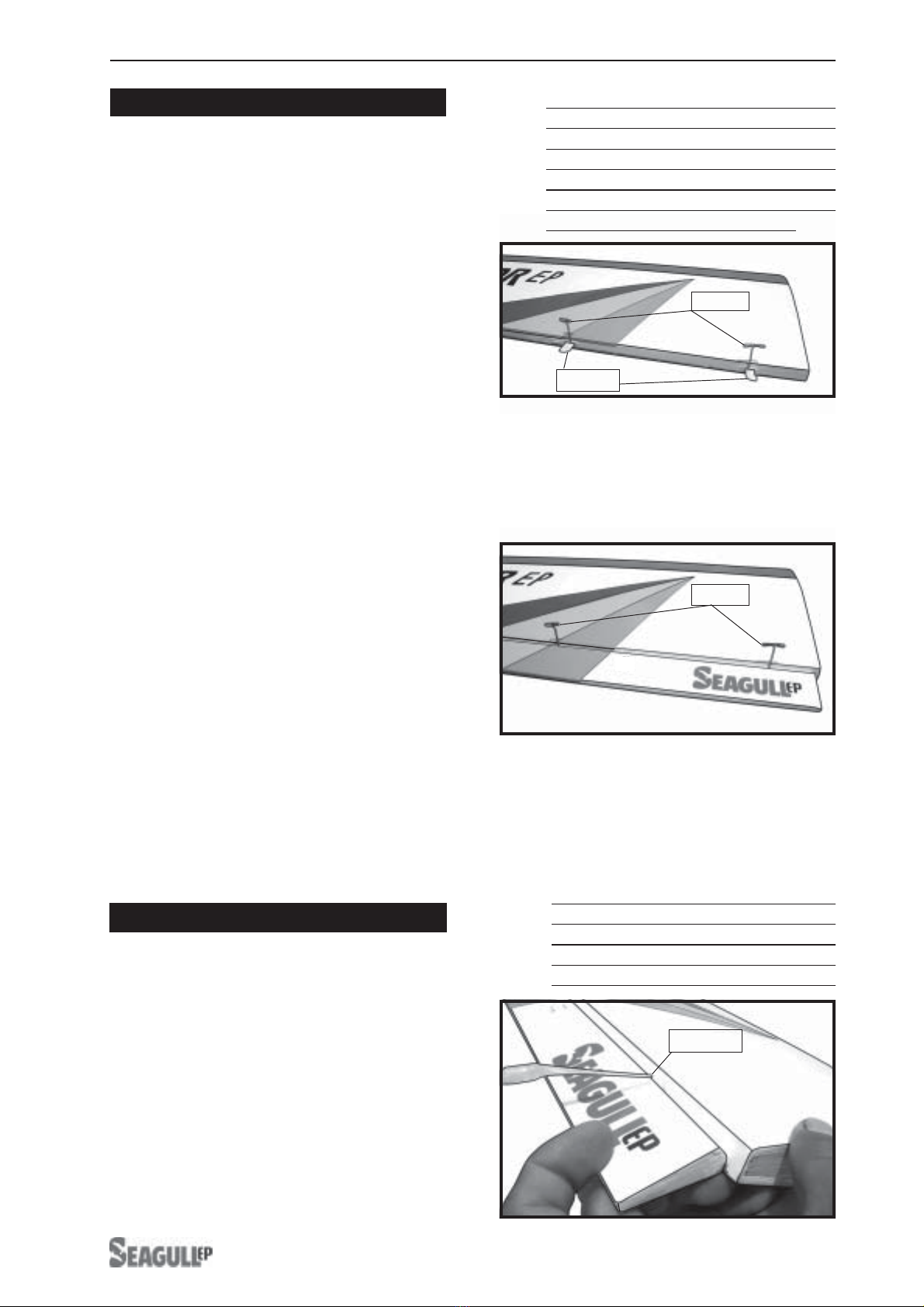
T - pin.
Hinges.
T - pin.
NOTE: To avoid scratching your new aero-
planewesuggestthatyoucoveryour
workbench with an old towel. Keep a
couple of jars or bowls handy to hold
the small parts after you open the
bags.
Pleasetrialfitallparts.Makesureyou
have the correct parts and that they
fit and are aligned properly before
gluing! This will ensure proper as-
semblyasthe INNOVATORismade
from natural materials and minor ad-
justments may have to be made.
The paint and plastic parts used in
this kit are fuel proof. However, they
arenottolerantofmanyharshchemi-
cals including the following: paint
thinner, cyano-acrylate glue accel-
erator,cyanoacrylategluede-bonder
andacetone.Do notletthesechemi-
calscome in contact with thecolours
onthecovering andtheplastic parts.
TOOLS & SUPPLIES NEEDED.
!Thick cyanoacrylate glue.
!30 minute epoxy.
!5 minute epoxy.
!Hand or electric drill.
!Assorted drill bits.
!Modellingknife.
!Straight edge ruler.
!2mm ball driver.
!Phillips head screwdriver.
!220 grit sandpaper.
!90° square or builder’s triangle.
!Wire cutters.
!Masking tape & T-pins.
!Thread-lock.
!Paper towels.
!1) Carefully remove the aileron from one
of the wing panels. Note the position of the
hinges.
!2)Removeeach hingefromthe wing panel
and aileron and place a T-pin in the center of
each hinge. Slide each hinge into the wing
panel until the T-pin is snug against the wing
panel. This will help ensure an equal amount
ofhingeis on eithersideof the hingelinewhen
the aileron is mounted to the aileron.
HINGING THE AILERONS.
!3) Slide the wing panel on the aileron until
there is only a slight gap. The hinge is now
centered on the wing panel and aileron.
Remove the T-pins and snug the aileron
against the wing panel.A gap of 1/64” or less
shouldbe maintainedbetween the wingpanel
andaileron.
!4)Deflect the aileron and completely
saturate each hinge with thin C/A glue. The
aileronsfrontsurface shouldlightlycontactthe
wing during this procedure. Ideally, when the
hinges are glued in place, a 1/64” gap or less
will be maintained throughout the lengh of the
aileron to the wing panel hinge line.
The hinge is constructed of a special
material that allows the C/A to wick or
penetrateanddistribute throughoutthe
hinge, securely bonding it to the wood
structureof thewingpanel andaileron.
Note:
C/Aglue.
The control surfaces, including the
ailerons, elevators, and rudder, are
prehinged with hinges installed, but the
hinges are not glued in place. It is
imperativethat youproperly adherethe
hingesin placeper thesteps thatfollow
using a high-quality thin C/A glue.
Note:
INNOVATOR-EP.Instruction Manual.
4
HINGING THE RUDDER.
!7) Repeat this process with the other wing
panel, securely hinging the aileron in place.
!5)Turnthe wingpanelover anddeflect the
aileron in the opposite direction from the
opposite side. Apply thin C/A glue to each
hinge,makingsurethattheC/Apenetratesinto
both the aileron and wing panel.
!6) Using C/A remover/debonder and a
papertowel, removeanyexcess C/Aglue that
may have accumulated on the wing or in the
aileronhinge area.
HINGING THE ELEVATOR.
Work the aileron up and down several
times to “work in” the hinges and check
for proper movement.
Note:
Glue the elevator hinges in place using the
same tectniques used to hinge the ailerons.
Glue the rudder hinges in place using the
same tectniques used to hinge the ailerons.
INSTALLING ELECTRIC MOTOR.
!8)Afterbothailerons are securely hinged,
firmly grasp the wing panel and aileron to
make sure the hinges are securely glued and
cannot be pulled out. Do this by carefully
applying medium pressure, trying to separate
the aileron from the wing panel. Use caution
not to crush the wing structure.
!1) Trial fit the motor on the firewall. The
motorshouldbepositioned sothereisaample
clearance in the fuselage end side for the
spinner backplate mounted to the propeller
drive shaft.
!2) Marking four points on the firewall. Drill
4 pilots horn 4.5mm diameter.
!3) Insert 4 blind nuts at the back side of
firewall. See picture below:
Insert 4 blind nuts.
Remove the covering.
www.seagullmodels.com
5
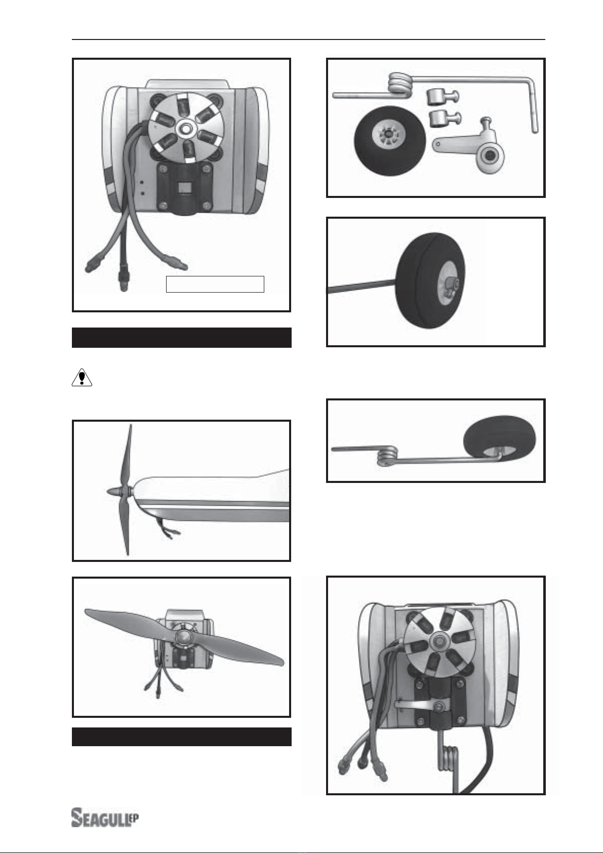
PROPELLER INSTALLATION.
The propeller should not touch any part
of the fuselage side.
3) Adjust the nose gear steering arm until
the arm is parallel with the firewall.
4) Install the pushrod wire as shown.
2) Mounting the nose gear as shown in the
following pictures.
NOSE GEAR INSTALLATION.
1) Assemble the nose wheel as shown in
the following pictures.
MOTORInstalltion.

INNOVATOR-EP.Instruction Manual.
6
INSTALLING THE MAIN WHEELS.
Assemble and mounting the wheel as same
asthe way ofnose wheel.Seepictures below:
!1) Using a modeling knife, remove the
covering from over the main gear mounting
slots located in the bottom of the fuselage.
INSTALLING THE STEERING ARM
SERVO.
Lock tie.
Attach the micro control connector to the
servo arms. Be sure to use the lock tie but it
could free rotation .
INSTALLING THE BATTERY- NOSE
GEAR SERVO .
See pictures below.
INSTALLINGTHE MAIN LANDING GEAR.
Battery.
No
Servo arm.
Nose gear servo.
Remove
the covering.
Battery.
Battery.
1mm
Steering pushrod wire.
Steering servo.
Fuselage bottom.
Tie wrap.

www.seagullmodels.com
7
!2) Insert the main gear wire into the
mounting slot .Using the hardware provided,
mount the main landing gear to the fuselage.
!3) The landing gear wire is held in place
using two nylon landing gear straps and four
3mm x 10mm wood screws.
AILERON SERVOS-LINKAGES.
! 1) Install the metal connector onto servo
arm as same as picture below.
Attach the micro control connector to the
servo arms. Be sure to use the lock tie but it
could free rotation .
! 3)Secure the servos with the screws pro-
vided with your radio system.
!2) Turn the wing panel right side up. Using
amodelingknife,removethe covering atservo
tray.
Attach the thread to the servo lead and
carefully thread it though the wing.
Install the rubber grommets and brass collets
onto the aileron servo. Test fit the servo into
the aileron servo mount.
Because the size of servos differ, you
mayneedtoadjustthesizeoftheprecutopen-
ing in the mount. The notch in the sides of
themountallowtheservoleadtopassthrough.
! 4) Insertaileron controlhorn totheaileron.
as same as picture below.
Lock tie.
Servo arm.
Control horn.
Control horn.
Wing bottom.
Remove the covering.
(3 x 10)mm
wood screws.
Nylonlanding
gear strap.
2mm x 20mm

Repeat the procedure for orther wing
haft.
TAIL SERVOS-LINKAGES.
Repeat the procedure as same as the
wing .
See pictures below:
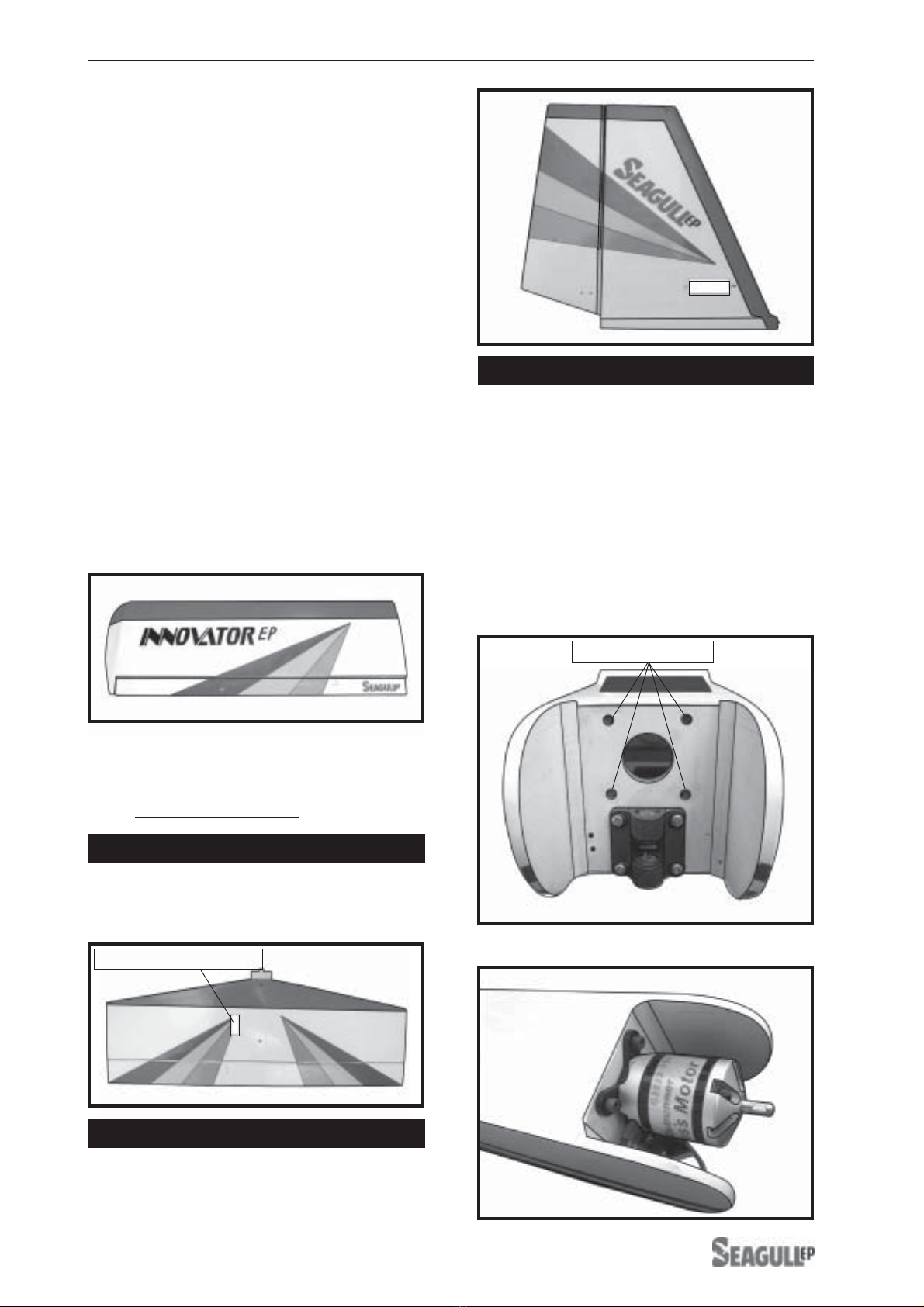
ASSEMBLY THE TAIL FIN.
INSTALLING THE FUSELAGE PARTS.
Tailmounting.
Remove the covering.
8
See pictures below:
Wing brace.
Fuselage brace.
Fuselage bottom.
M3x15mm machine scvew.
Wing bottom.
Control horn.
Verticalfin.
Pushrod.
Pushrod.
Control horn.
Horizontal fin bottom.
Remove the covering.
Fuselage bottom.
Electric
servo wire.

ATTACHMENT WING-FUSELAGE.
Attach the aluminium tube into fuselage.
Insert two wing panels as pictures below:
9
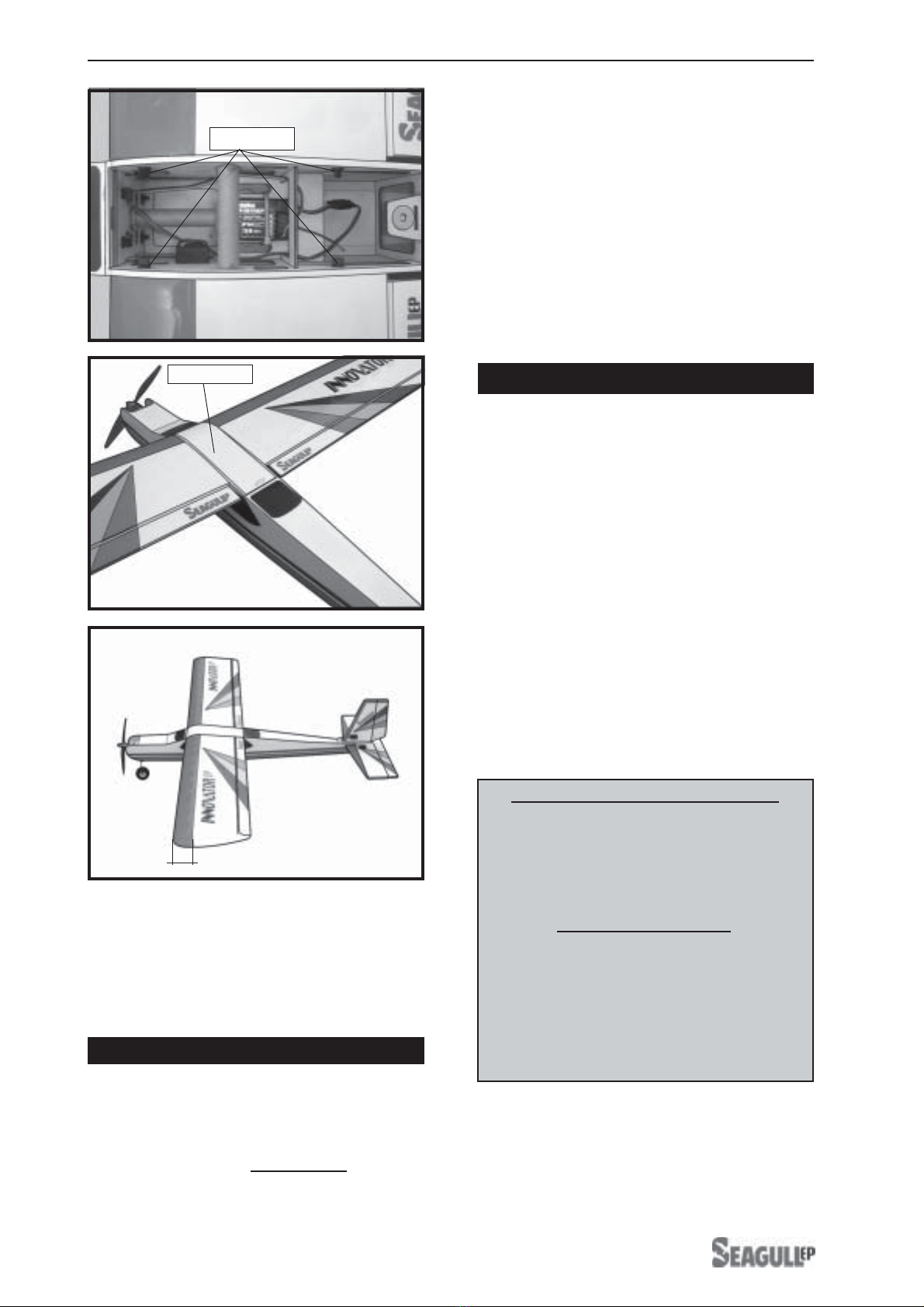
INSTALLING THE RECEIVER.
Wing brace.
Plastic bolt.
Battery.
Fuselage bottom
Remove the covering.
Switch.
Plastic bolt.
Receiver.
Electric wires.
INNOVATOR-EP.Instruction Manual.
10
INITIAL FLYING/SPORT FLYING
Ailerons: 3/8” up 3/8” down
Elevator: 3/8 ” up 3/8” down
Rudder: 1/2” right 1/2” left
AEROBATIC FLYING
Ailerons: 1/2”up 1/2”down
Elevator: 5/8”up 5/8”down
Rudder: 1” right 1”left
Do not use the aerobatic settings for
initial test flying or sport flying.
! 4) By moving the position of the adjust-
able control horn out from the control surface,
you will decrease the amount of throw of that
control surface. Moving the adjustable con-
trol horn toward the control surface will in-
crease the amount of throw.
!1) It is critical that your airplane be bal-
anced correctly. Improper balance will cause
yourplane to losecontrol and crash. Thecen-
ter of gravity is locate 5.5-6.5cm back from
theleadingedgeofthewing,measuredatwing
tip.
BALANCING.
!2) If the nose of the plane falls, the plane
is nose heavy. To correct this first move the
battery pack further back in the fuselage. If
this is not possible or does not correct it, stick
small amounts of lead weight on the fuselage
sides under the horizontal stabilizer. If the tail
of the plane falls, the plane is tail heavy. To
correctthis, move thebattery andreceiverfor-
ward orif this is not possible, stick weight onto
the firewall. When balanced correctly, the air-
plane should sit level or slightly nose down
when you lift it up with your fingers.
!1) We highly recommend setting up the
INNOVATOR. using the control throws listed at
right. We have listed control throws for both
Low Rate (initial test flying/sport flying) and
High Rate (aerobatic flying).
CONTROL THROWS.
! 3) When the elevator, rudder and aileron
control surfaces are centered, use a ruler and
check the amount of the control throw in each
surface. The control throws should be
measured at the widest point of each sur-
face!
!2) Turnon theradio system,and withthe
trim tabs on the transmitter in neutral, center
the control surfaces by making adjustments
totheclevises oradjustableservo connectors.
The servo arms should be centered also.
5.5 - 6.5 cm
Top hatch.
Wing bolt.

www.seagullmodels.com
11
FLIGHT PREPARATION.
! A) Check the operation and direction of
the elevator, rudder, ailerons and throttle.
! B) Plug in your radio system per the
manufacturer's instructions and turn every-
thingon.
! E)Check the throttle.
! D) Check the rudder. Looking from be-
hindthe airplane, movethe rudderstick to the
right. Therudder should moveto the right. Ifit
does not, flip the servo reversing switch on
your transmitter to change the direction.
! C) Check the elevator first. Pull back on
theelevator stick. Theelevator halvesshould
move up. If it they do not, flip the servo re-
versing switch on your transmitter to change
the direction.
! F)From behind the airplane, look at the
ailerononthe rightwinghalf. Movethe aileron
sticktotheright. Therightaileronshouldmove
upand theotheraileron shouldmovedown. If
it does not, flip the servo reversing switch on
your transmitter to change the direction.
!5) If your radio transmitter is equipped
withdual rateswitches double checkthat they
are on the low rate setting for your first few
flights.
!6) Check to ensure the control surfaces
are moving the proper amount for both low
and high rate settings.
!8) Properlybalance thepropeller. An out
of balance propeller will cause excessive vi-
bration which could lead to engine and/or air-
frame failure.
We wish you many safe and enjoyable
flights with your INNOVATOR.
!7) Check the receiver antenna. It should
be fully extended and not coiled up inside the
fuselage.
PREFLIGHT CHECK.
!1) Completely charge your transmitter
and receiver batteries before your first day of
flying.
!2) Check every bolt and every glue joint
inthe INNOVATOR toensure thateverything is
tight and well bonded.
!3) Double check the balance of the air-
plane. Do this with the fuel tank empty.
!4) Checkthe controlsurfaces. All should
move in the correct direction and not bind in
any way.
Table of contents
Other Seagull EP Toy manuals

Popular Toy manuals by other brands


Little Tikes
Little Tikes 485121M instructions

Oregon Scientific
Oregon Scientific Star Wars Darth Vader Laptop DV33 owner's manual

Trix
Trix E 44 Series manual

Little Tikes
Little Tikes Sparkle Bay Flicker Fish quick start

Fisher-Price
Fisher-Price HOT WHEELS SMART CYCLE L1774 manual

LEGO
LEGO The Ninjago movie 70609 Assembly instruction


