3. SPECIFICATION
Model no: ................................................................. SA24.V2
Chuck size: ............................................................... Ø10mm
Free speed:..............................................................1800rpm
Air consumption: ............................................................ 4cfm
Operating pressure: ...................................................... 90psi
Inlet size:...................................................................1/4”BSP
Weight:.......................................................................... 1.1kg
Noise power/pressure: ............................................103/92dB
Vibration/uncertainty: ......................................... 2.06/0.7m/s²
4. PREPARATION
4.1. Air Supply
WARNING! Ensure the air supply is clean and does not exceed 90 psi while operating the drill. Too high an air pressure and unclean
airwillcauseexcessivewear,andmaybedangerous,causingdamageand/orpersonalinjury.
4.1.1. Ensure the drill air valve (or trigger) is not depressed before connecting to the air supply.
4.1.2. Youwillrequireanairpressurebetween70-90psi,andanairowaccordingtothespecicationabove.
4.1.3. Drain the air tank daily. Water in the air line will damage the drill and invalidate your warranty.
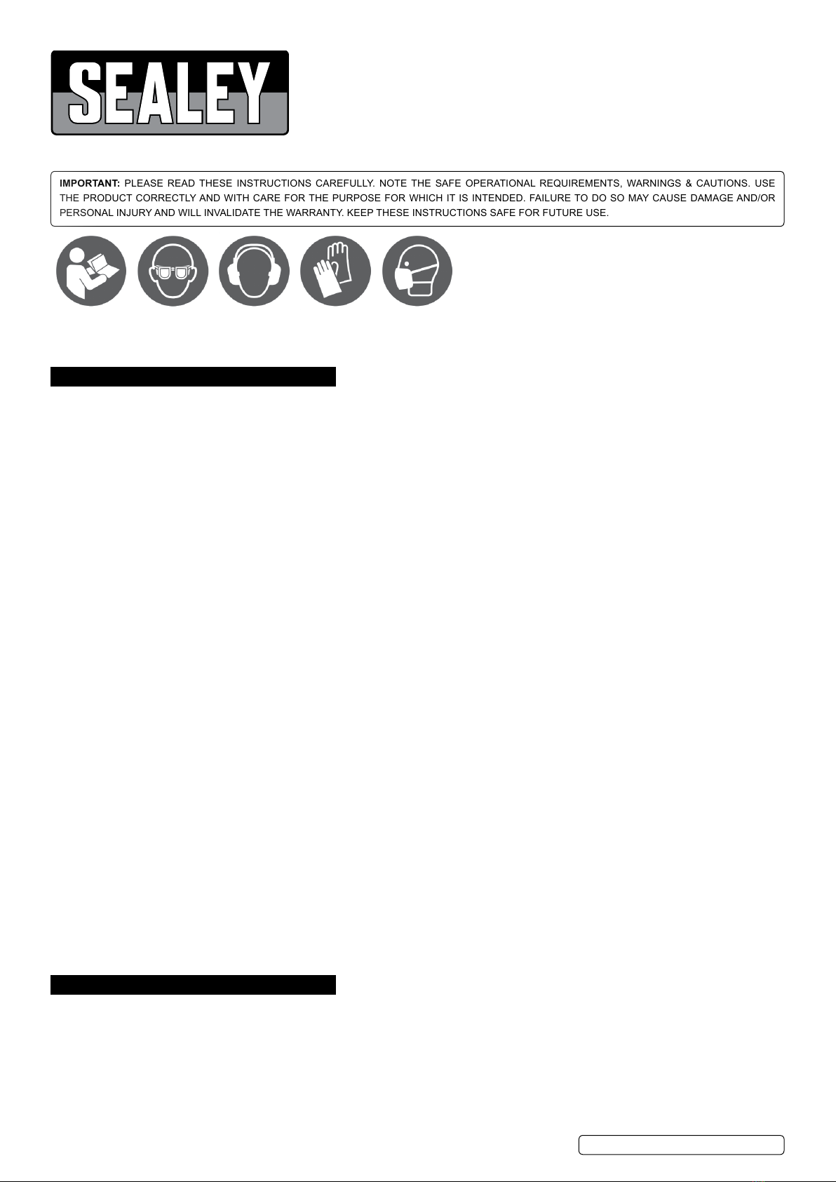
4.1.4. Cleanairinletlterweekly.Recommendedhook-upprocedureisshowning1.
4.1.5. Line pressure should be increased to compensate for unusually long air hoses (over 8 metres).
4.1.6. Theminimumhosediametershouldbe1/4”I.D.andttingsmusthavethesameinsidedimensions.
4.1.7. Keep hose away from heat, oil and sharp edges. Check hoses for wear, and make certain that all connections are secure.
4.2. Couplings
4.2.1. Vibrationmaycausefailureifaquickchangecouplingisconnecteddirectlytotheairdrill.Toovercomethis,connectaleaderhose-
SealeymodelnumberAH2RorAH2R/38-tothedrill.Aquickchangecouplingmaythenbeusedtoconnecttheleaderhosetothe
airlinerecoilhose.Seegs.1&2.
5. OPERATION
WARNING! Ensure you read, understand and apply safety instructions before
use.
5.1. Drill bit tting
WARNING! Unplug from the air supply before placing bit into chuck.
5.1.1. Regularly check the drill bit and always change if worn, cracked or otherwise damaged.
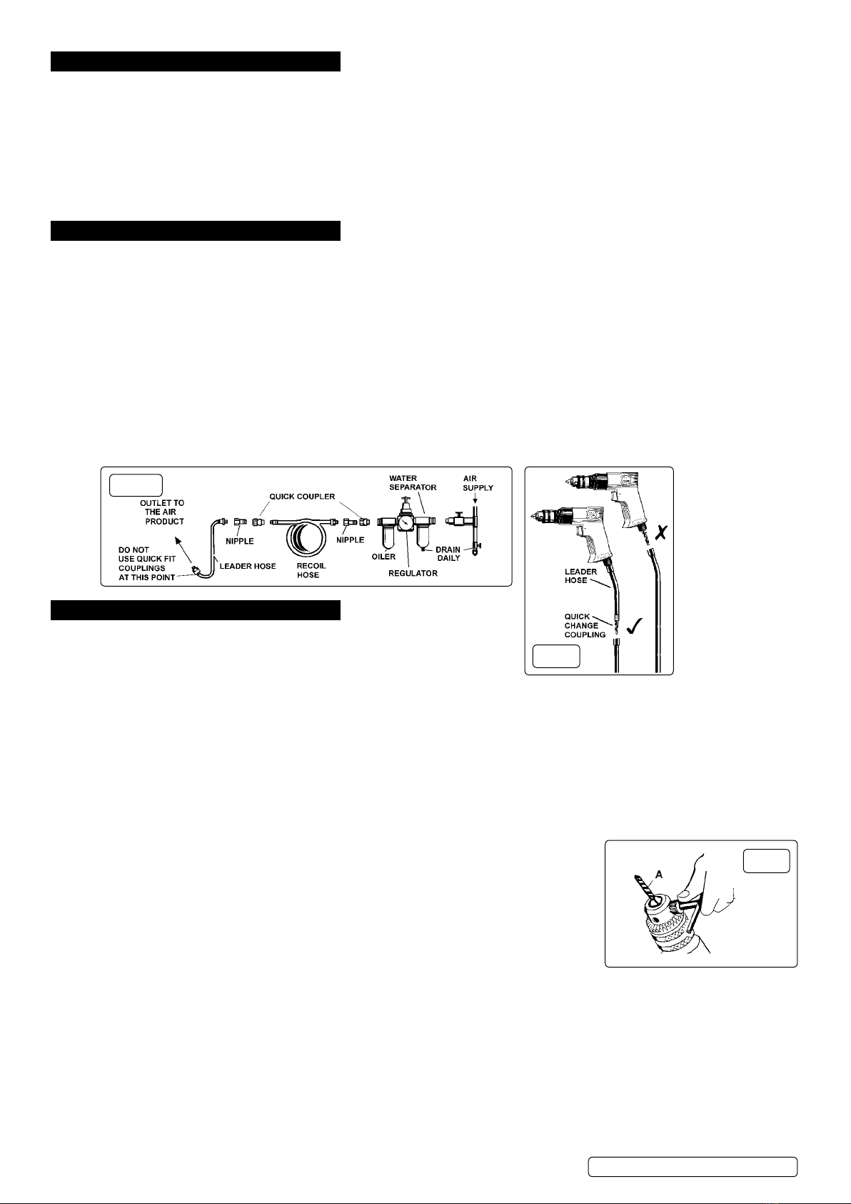
5.1.2. Openorclosethechuckjawstoapointwheretheopeningisslightlylargerthanthedrillortoolbit(g3A)tobeused.Insertthedrill
bit into the chuck as far as it will go. Place the chuck key in one of the chuck holes and tighten the chuck securely.
WARNING! Ensure you remove the chuck key before starting the drill.
5.1.3. Connect air supply to drill. Squeeze the trigger to check that the drill is working correctly before starting work.
8DO NOT allow drill to run freely for an extended period of time as this will shorten the life of bearings.
5.2. Standard Drilling instructions
WARNING!Ensureyouwearapprovedsafetygogglesandanyothersafetyitemsrequiredforthejob.
5.2.1. Remove the chuck key before using the drill. Also ensure that all other safety requirements are followed.
5.2.2. Connect drill to air supply.
5.2.3. Ensurethedrillisturningintheforwarddirectionbycheckingthattheleveradjacenttothe
trigger is next to the forward symbol (F). If not, push the lever over to the forward position.
5.2.4. Holdtoolrmlyandplacethebittiptothepointtobedrilled.
5.2.5. Depress the trigger to start drill. Move the drill bit into the work piece applying only enough
pressure to keep the bit cutting. DO NOT force or apply side pressure to elongate the hole.
5.2.6. If the material to be drilled is free standing it should be secured in a vice or with clamps to
keep it from turning as the drill bit rotates.
5.2.7. When drilling metals, use a light oil on the drill bit to keep it from overheating. Oil will
prolong life of bit and improve the drilling action.
5.2.8. For hard smooth surfaces use a centre punch to mark desired hole location. This will prevent
bit from slipping as your start to drill.
5.2.9. Apilotholemaybenecessarytoassistthenaldrillsizethroughtheworkpiece.Lockapilotdrill(smallersizedrillthanthenished
holesize)intothechuck.Followsteps5.2.2.to5.2.4.aboveanddrillapilotholeinthemiddleofthecentrepunchmarkwherenal
holeistobedrilled.Insertthenalsizedbitinchuck.Holddrillrmly,placethebitattheentranceofthepilotholeanddepressthe
trigger.
WARNING! Be prepared for drill binding or break through. When these situations occur the drill has a tendency to grab and kick in
the opposite direction which could cause loss of control. If you are not prepared, this loss of control can result in damage and/or
personalinjury.
5.2.10. Ifthebitjamsintheworkpieceorifthedrillstalls,releasethetriggerswitchimmediately.Removethebitfromtheworkpieceand
determinethereasonforjamming.Itmaybenecessarytoreversethedirectionofrotationbymovingtheleveradjacenttothetrigger
to the reverse (R) position.
fig.2
fig.1
fig.3
Original Language Version
© Jack Sealey Limited SA24.V2 | Issue 5(L) 06/10/17