Sealweld SuperGun User manual
Owner’s Manual - Sealweld SuperGun® Content
Page i
Owner's Manual - Original Instructions
Doc. No. 100005
Rev 0
Sealweld SuperGun®
By Sealweld Corporation

Owner’s Manual - Sealweld SuperGun® Content
Page ii
This document is for the purpose of the Sealweld SuperGun®operation only and is not considered a
guide for valve maintenance. We are pleased to offer a valve maintenance program “ValvePro®” and
trust you will find the lessons detailed in this program useful when maintaining the valves at your facility.
Should you have any questions regarding any of the ValvePro® procedures or if you know of any
successful procedures you would like to share, please contact us at:
Sealweld Corporation
# 106, 4116-64 Ave. S.E., Calgary, Alberta, Canada T2C 2B3
Telephone: 1-403-236-0043 Fax: 1-403-236-5487
TOLL FREE 1-800-661-8465
Email: info@sealweld.com
Web Site: www.sealweld.com
Sealweld (USA), Inc.
11430 Brittmoore Park Dr., Houston, Texas, USA 77041
Telephone: 1-713-466-7373 Fax: 1-713-466-7778
TOLL FREE 1-800-624-4301
Email: info@sealweld.com
Web Site: www.sealweld.com
ValvePro® Technical Support
Telephone: 1-403-236-0043 Fax: 1-403-236-5487
Email: support@valvepro.com
Web Site: www.valvepro.com
The information in this manual is intended as a guide only.
Read our Disclaimer on page 29.
Always consult the valve manufacturers recommended maintenance procedures.
Sealweld®, ValvePro® and FLOW WOLF® are registered trademarks and/or patents of Sealweld
Corporation.
MADE IN CANADA
Revised 4/24/2014

Owner’s Manual - Sealweld SuperGun® Content
Page iii
Contents
Introduction 1
The Sealweld SuperGun® Pump.....................................................................1
SAFETY EXPLANATIONS ...........................................................................................1
Technical Data 3
Safety Considerations 4
SuperGun Specific Safety Considerations.......................................................4
Personal Safety ...............................................................................................5
High Pressure Hose.........................................................................................5
Operating Instructions 6
Release Valve Fundamentals..........................................................................6
How to Operate a SuperGun ...........................................................................6
Loading Instructions 9
How to Load a SuperGun ................................................................................9
Prepare for Loading ......................................................................................................9
To Load a Cartridge....................................................................................................10
With an EZ-LOADER .................................................................................... 10
Without an EZ-LOADER............................................................................... 11
To Load a Bag or Stick Type Product.........................................................................12
Care and Maintenance 13
Simple Rules..................................................................................................13
SuperGun Maintenance.................................................................................14
Check Valve Repair and Replacement.......................................................................14
Primer Rod Assembly Removal and Repair ...............................................................15
Piston Cartridge Assembly Replacement ...................................................................18
Hose Assembly Replacement.....................................................................................19
Linkage Repair and Replacement...............................................................................19
Pressure Gauge Replacement....................................................................................21
Storing the SuperGun....................................................................................21
Parts Guide 23
Parts Illustration.............................................................................................23
Parts List........................................................................................................24
How to Order SuperGun Parts.......................................................................25
Repair Kits...................................................................................................................25
Troubleshooting 27
Troubleshooting the SuperGun......................................................................27
Testing the SuperGun.................................................................................................27
Warranty 30
SuperGun Warranty.......................................................................................30
Disclaimer......................................................................................................30
EC Declaration of Conformity ........................................................................31
Contact Information .......................................................................................32
Owner’s Manual- Sealweld SuperGun® Introduction
Page 1
Introduction
The Sealweld SuperGun® Pump
SAFETY EXPLANATIONS
Two safety symbols are used to identify where any action or lack of action can cause personal injury. It is very
important that the user reads and understands the use of these symbols.
DANGER! –Danger is used only when an action or lack of action will cause serious human injury or
death.
WARNING! –Warning is used when an action or lack of action can lead to a serious injury.
IMPORTANT! –Important is used when an action or lack of action can cause equipment failure,
either over a long period of time or immediately.
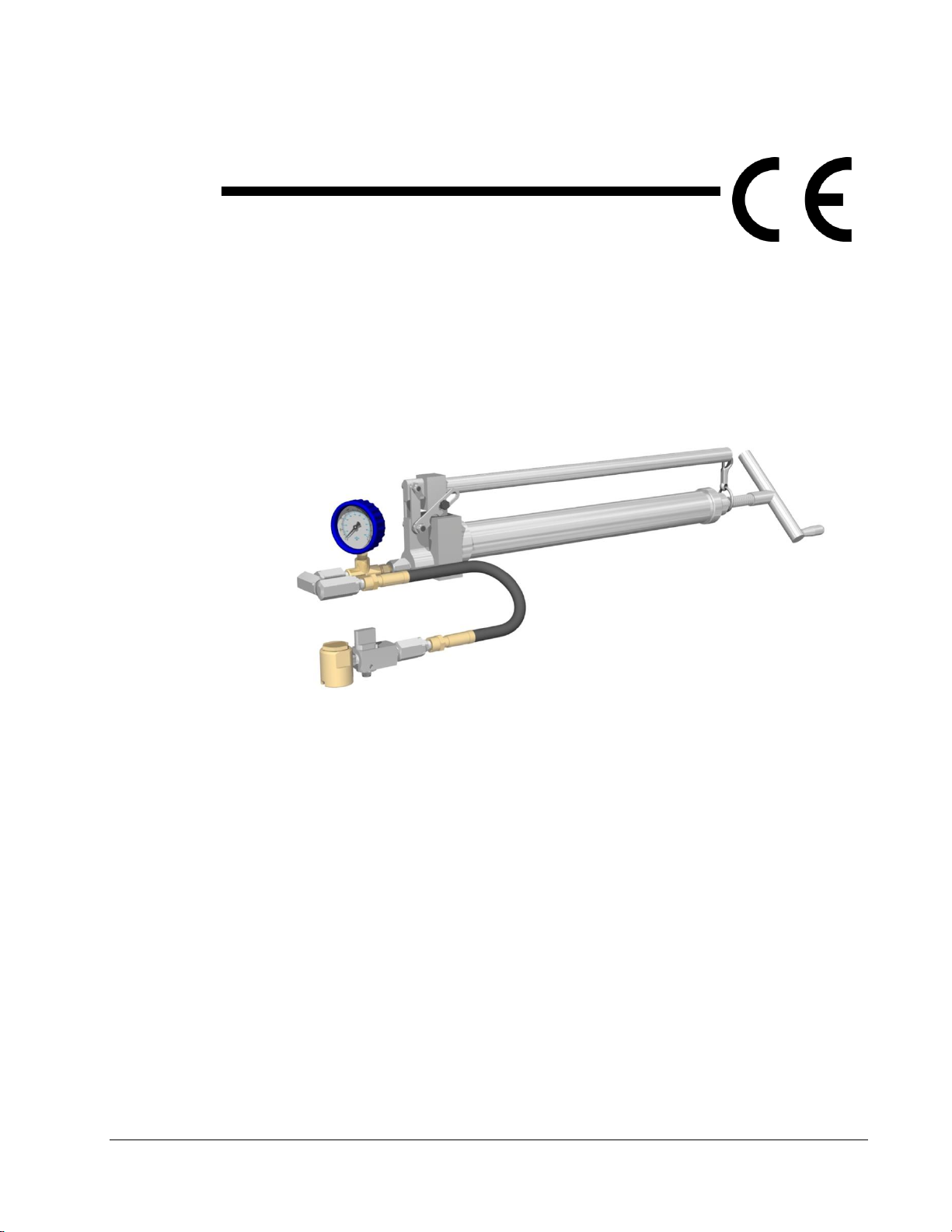
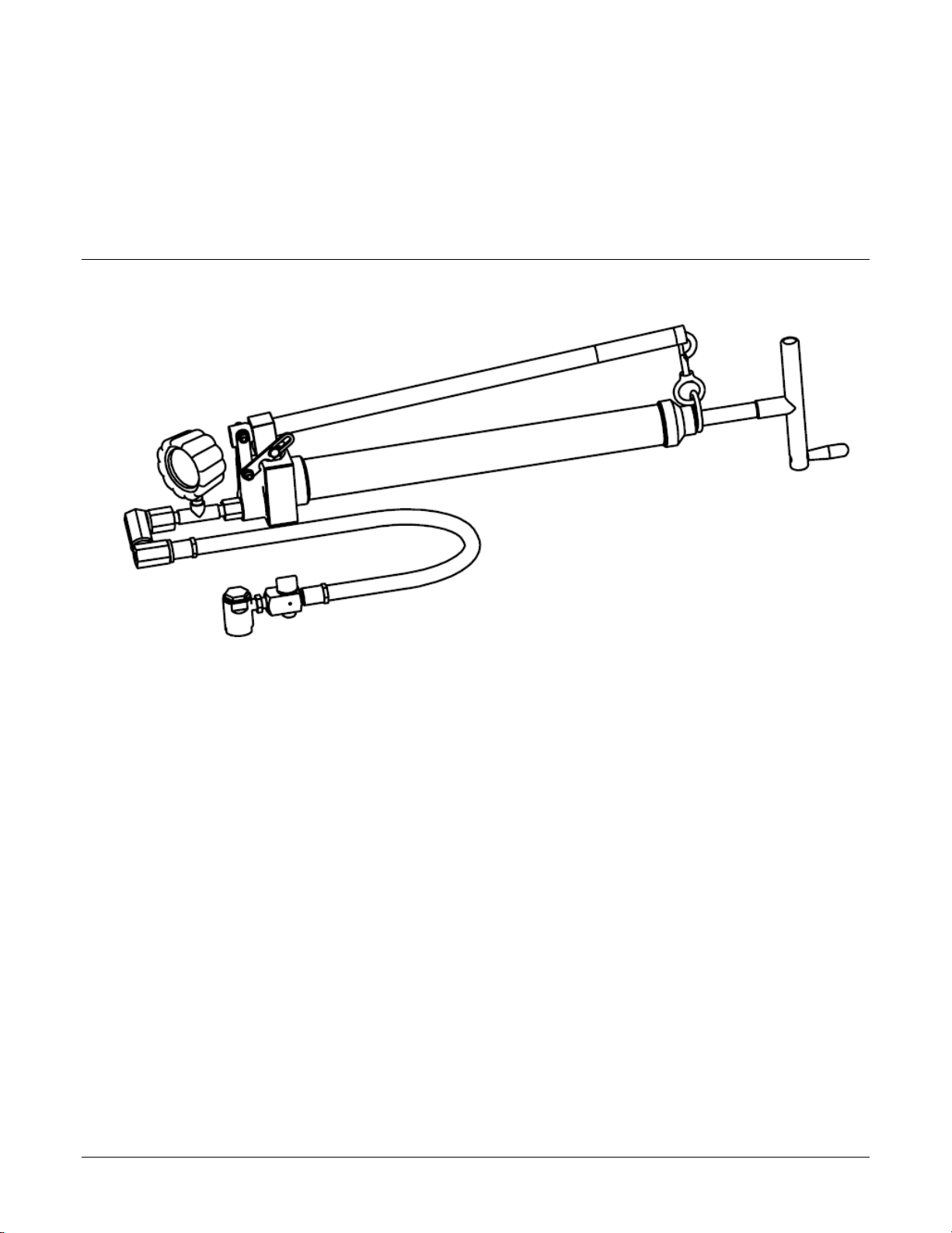
The SuperGun is a screw-primed hand-held manual injection pump that can generate up to 15,000psi (1034 bar),
if required. The SuperGun was developed by correcting design deficiencies in the older styles of screw primed
pumps.
The field replaceable piston cartridge cuts repair costs by over 75% compared to similar equipment. The sealant
barrel was enlarged 33% so that fewer refills would be required and so that it would hold the contents of a regular
16 oz. (470 ml) cartridge. Several other enhancements were added to make the SuperGun more durable, easy to
carry and pump faster. The SuperGun will discharge approximately 1 oz. (30 ml) of product with every 25 strokes
of the handle, making it the valve technicians favourite pump for routine topping-up procedures when only small
quantities of product is required.
Features include:
Locking handle to prevent damage occurring to the SuperGun.
Easy to handle, very portable.
Crank-priming action makes manual injection simple.
Generates up to 15,000psi (1034 bar) when required.
Easily reloads with cartridge, bag or stick type products.
Holds up to 16 ounces (470ml) of product.
Discharges approximately one ounce (30ml) of product easily with every 25 strokes.
Easy to read High Pressure Gauge.
Buttonhead Coupler quickly connects and disconnects to fittings.
Extra heavy duty construction design for rugged field use.
The SuperGun ships with an 18 inch (46 cm) long hose, buttonhead coupler and high pressure gauge. It is ready
to load and use right out of the box. The working principle is simple; turn the crank in to prime the SuperGun, the
Owner’s Manual- Sealweld SuperGun® Introduction
Page 2
handle is stroked and the piston pushes the product out through the hose assembly. Continue stroking the
handle and the pressure will continue to increase. After 50 to 75 strokes of the handle you will need to turn the
Primer Rod Crank #12 to inject more product.
Once the valve line pressure is exceeded product will begin to flow into the valve. When a sufficient quantity of
product has been injected the SuperGun may be removed by opening the release valve then slipping off the giant
buttonhead coupler from the buttonhead fitting.
WARNING -READ THIS MANUAL THOROUGHLY BEFORE OPERATING
Refer to the illustration on page 23 for all references to part numbers in this manual.
Owner’s Manual- Sealweld SuperGun® Technical Data
Page 3
Technical Data
The Supergun, when empty, weighs about 18.5 lbs (8.4 kg) and is therefore very portable. It measures about 33
inches (84cm) with the crank turned all the way in. It can be loaded with 12 ounce or 16 ounce cartridges from an
EZ-loader, and it also pumps ‘K’ sticks, Gun-Packs and all types of bulk lubricants/sealants. The screw-primed
design makes it easy to keep track of how much product remains in the barrel. The piston can generate up to
15,000 PSI (1000 bar), but only a small volume of product is pressurized at a time. The SuperGun comes with an
18inch (46 cm) high pressure hose assembly with a 15,000PSI gauge. The pump discharges approximately 1
ounce (30ml) of sealant per 25 strokes.

Owner’s Manual- Sealweld SuperGun® Safety Considerations
Page 4
Safety Considerations
SuperGun Specific Safety Considerations
WARNING!
Sealweld Products are designed for industrial use only and the SuperGun should only be used by a
Certified Valve Technician who is familiar with the working principals, mechanical limitations &
working pressures of the valve being serviced. When working with pressurized valves and pipelines
use extreme caution and do not take risks or short cuts. Always have a proper size stabbing valve
ready in case of a valve fitting failure.
The SuperGun has no internal relief functionality and the amount of pressure it can generate can be
very dangerous. Under normal working condition most valves can be serviced with a pressure below
4,000psi (276 bar). Occasionally you may be required to generate a pressure up to 10,000psi (690
bar). It is very rare that more than 10,000psi (690 bar) is required to service a valve. You must
approach it as extremely dangerous when doing so.
When working with valves in a toxic or low O2deficient environment, ALWAYS wear a self contained
breathing apparatus and have backup safety watch standing by. Use extreme caution before opening
a body vent fitting.
ALWAYS consult the Valve Manufactures manual prior to commencing work on any valve. Do not
exceed working pressure of valve when filling the body cavity. NOTE: Keep injection pressure below
4000 psi (276 bar) on cast iron or semi steel valves.
Never hit the Giant Buttonhead Coupler #13H with hammer or other object to connect or disconnect
the coupler from a fitting. Doing so may result in damaging or breaking the fitting which could cause
serious personal injury or death.
In the event where the valve being serviced internal checks fail it will be very difficult or impossible to
remove Giant Buttonhead Coupler #13H. Ensure that you have all the proper tools, procedures and
product readily available should this problem arise.
NEVER operate a pump without a properly functioning pressure gauge or if the gauge shows signs of
over pressurization or is in poor operating condition. Use EXTREME CAUTION when generating
10,000psi (690 bar) or more.
ALWAYS leave the Release Valve #13G in the closed position to prevent sealant from escaping
when the SuperGun is not in use. See “Storing the SuperGun” on page 21.
Do not use a pump if it has been damaged. Use a mild solvent & clean cloth to keep the SuperGun in
clean operating condition.
NEVER carry the SuperGun by its Handle #5 unless it has been latched and secured.
Hydraulic pressure created inside the valve with a high pressure pump can stretch bolts on bolted
plug valve and cause leakage. Should this occur, release pressure by opening Release Valve #13G.
The flange should sit back down and leakage should stop.

Owner’s Manual- Sealweld SuperGun® Safety Considerations
Page 5
Light valve lubricants, cleaners or liquid products can become a dangerous projectile in the event of
a hose or fitting failure while under high pressure.
Be very CAREFUL to keep fingers and hand away from the vent hole on the side of the Release
Valve #13G when opening. A short stream of sealant can shoot out at extremely high pressure.
Do not remove labels. Maintain labels and nameplates on this product. These carry important
information.
Personal Safety
WARNING!
Stay alert. Do not use the SuperGun while tired or under the influence of alcohol, drugs or medications.
Dress properly. Always wear approved Personal Protective Equipment (PPE). Do not wear loose clothing or
jewellery. Contain long hair. Keep your hair, clothing and gloves away from moving parts.
At all times, keep proper footing and balance, maintain a firm grip when using any sealant pump, and do not
over-reach.
Maintain a safe working environment. Keep a clean work site. Ensure that you have proper lighting and that
you have completed a Job Hazard Assessment (JHA). Ensure that you have the proper work permits and that
your fellow workers are aware of the procedures and scope of work that you are about to perform.
ALWAYS turn off your vehicle and work well down wind of all sources of spark or ignition.
High Pressure Hose
WARNING!
Use only Sealweld Corporation replacement parts and hoses.
NEVER carry the SuperGun by the Hose Assembly #13.
Hose life is reduced by factors that include:
Environment - Temperature extremes, UV light, chemicals, ozone, etc. will degrade the rubber used in
hydraulic hoses.
Abrasion and Cuts - Wear against other hoses or objects will wear off the outer cover and lead to
corrosion of the reinforcing mesh.
Extreme Pressure Fluctuations - Pressure surges above the hose working pressure will damage hose
components.
Improper Length/Routing - Excessive bending of the high pressure hose causes high stresses in the
hoses components that may also reduce pressure capacity (avoid multi-plane bending, small bend radii,
tension in hose, etc.). Hose life can be reduced by 90% when subject to these type of stresses.
Owner’s Manual- Sealweld SuperGun® Operating Instructions
Page 6
Operating Instructions
Release Valve Fundamentals
The Release Valve #13G supplies a means of releasing pressure in the Giant Buttonhead Coupler #13H so it can
be easily detached from a buttonhead fitting. It has three positions used in its operation, Opened, Vented and
Closed.
When Opened, the Release Valve knob is in alignment with the Hose Assembly #13 and product can
be pumped through the Giant Buttonhead Coupler #13H and into the valve.
When Vented, it is at a 90° angle to the Hose Assembly #13. Product cannot be pumped and any
product under pressure in the Giant Buttonhead Coupler #13H will be allowed to escape through the
Release Valve #13G vent hole.
When Closed, the knob is at a 45° angle to the Hose Assembly #13. Product cannot be pumped into
the valve or escape through the Release Valve #13G vent hole. Set the Release Valve #13G in this
position when the SuperGun is not in use.
WARNING! Be very CAREFUL to keep fingers and hands away from the vent hole on the side of the
Release Valve #13G when operating this valve. Product can shoot out at extremely high pressure and may
cause injuries.
DANGER! When venting the Release Valve #13G, in the event the Giant Buttonhead fitting’s
internal check valve fails, product will continuously dispense through the vent hole and eventually pipeline product
will follow. Ensure that you have all the proper tools, procedures & product readily available should this problem
arise.
NOTE: Depending on the product being pumped and the ambient temperature, the use of a wrench may be
required to ease the operation of the Release Valve #13G.
How to Operate a SuperGun
The SuperGun operator should be familiar with the working principals and the mechanical limitations of the
pipeline valve being serviced.
Before operating the SuperGun, read and remember the “Simple Rules” listed on page 13 in the “Care and
Maintenance” section of this manual.
IMPORTANT! Be sure you have read and understand the “Safety Considerations”section of this manual before
operating this pump.
NOTE: If at any time you feel the SuperGun is not operating as expected see “Troubleshooting” on page 27.
To operate the SuperGun:
1. The SuperGun must first be loaded. See “How to Load a SuperGun” on page 9.
2. Prime the SuperGun.

Owner’s Manual- Sealweld SuperGun® Operating Instructions
Page 7
To prime the SuperGun, turn the Primer Rod Crank #12 clockwise until it becomes difficult to turn.
IMPORTANT! Over-tightening the Primer Rod Crank #12 can damage and/or collapse the
Primer Rod Assembly #9.
3. Inspect the Giant Buttonhead Coupler #13H for damage and contaminates. Clean using a mild solvent
and a clean cloth if required before attaching to a fitting.
4. Set the Release Valve #13G in its opened position.
5. Attach the Giant Buttonhead Coupler #13H to a buttonhead fitting on the valve being serviced.
IMPORTANT! ALWAYS follow the valve manufacturer's recommendations and instructions
when servicing each type of valve.
WARNING! Always inspect the buttonhead fitting before attaching the Giant Buttonhead
Coupler #13H and keep a watchful eye out for dangerous two piece buttonhead fittings. Ensure
that you have all the proper tools, procedures & product readily available should a problem arise.
6. Release the Handle #5 from the Handle Clasp #11.
7. Lift the Handle #5 up until it reaches it full height.
Allowing the Handle #5 to rest a second while at its full height allows more product to enter the
piston cavity.
8. Pull the Handle #5 all the way down. Steps 7 and 8 together make one stroke.
When fully primed, the SuperGun will operate for 50 to 75 strokes before additional priming is
required. However, as the number of strokes increase the longer it will take for the piston cavity to
fill. For this reason it is common practice to prime the SuperGun every 25 to 50 strokes.
Many operators will rest the Head #6 on the pipeline or the valve to ease in the operation of the
SuperGun.
9. By stroking the Handle #5, product gets injected into the valve and pressure will begin to build. It could
require 10 to 15 full strokes before the pressure begins show on the High Pressure Gauge Assembly
#13C. As you stroke monitor the injection pressure.
NOTICE: Once you become familiar with reading the gauge properly you will be able to
judge when sealant begins to enter the valve. Consult "The Digital HANDBOOK of Valve
Lubrication & Maintenance" for more information on Pressure Gauge Reading
Techniques.
Watch for signs of leakage between the Giant Buttonhead Coupler and the valve fitting, once a
positive seal is achieved gauge pressure will begin to climb.
10. Once the required amount of product has been injected into the valve, slide the Giant Buttonhead Coupler
#13H off the fitting.
To slide the Giant Buttonhead Coupler #13H hold the Hose Assembly #13 near the coupler, tilt
down at slight angle and push off. Do not use excessive force.
Under normal conditions the Giant Buttonhead Coupler #13H can be removed relatively easily as
the pressure on the High Pressure Gauge Assembly #13C drops and returns to a near zero
reading. Occasionally additional force is required, place one hand over the Giant Buttonhead
Coupler #13H and press down as you slide it off. Be careful not use excessive force.
11. If the Giant Buttonhead Coupler #13H is difficult to remove from a fitting, turn the Release Valve #13G to
the Vented Position.
Be very careful to keep fingers and hand away from the vent hole on the side of the Release
Valve #13G when opening. Product will shoot out the vent hole at extremely high pressure.

Owner’s Manual- Sealweld SuperGun® Operating Instructions
Page 8
WARNING! In the event that the product continuously dispenses through the vent
hole, close the Release Valve #13G immediately as pipeline product is sure to follow.
Ensure that you have all the proper tools, procedures & product readily available should
this problem arise.
12. Repeat this procedure as required for each valve to be serviced.
When the SuperGun is not in use always relieve the internal pressure by turning the Primer Rod
Crank #12 counter-clockwise at least three turns and set the Release Valve #13G to the closed
position to prevent product from escaping.
Always connect the Handle #5 to the Handle Clasp #11 when carrying or storing/stowing the
SuperGun.

Owner’s Manual- Sealweld SuperGun® Loading Instructions
Page 9
Loading Instructions
How to Load a SuperGun
WARNING! Before attempting to load the SuperGun, ensure that all pressure has been released.
One of the many advantages of a screw-primed sealant injection pump is the ability to know how much sealant is
remaining in the barrel. When empty the Primer Rod Crank #12 will be screwed all the way in and there will be no
threads left showing between the End Cap #10 and the Primer Rod Crank #12.
The SuperGun can be loaded from either a cartridge or bag. It can also be loaded with a stick type product. It is
designed to hold up to 16 ounces (470 ml) in the Sealant Barrel #8.
All Loading instructions are based on the Giant Buttonhead Coupler #13H being detached from a
buttonhead fitting, all pressure in the Hose Assembly #13 has been relieved and Sealant Barrel #8 is
empty.
Prepare for Loading
1. Turn the Primer Rod Crank #12 counter-clockwise at least three full turns to relieve any compression on
Primer Rod Assembly #9.
2. Look at the High Pressure Gauge Assembly #13C to make sure pressure is at zero.
3. Unscrew the Sealant Barrel #8 from the Head #6.
4. Place the head assembly in a clean, dry place to avoid any contamination.
Periodically turn the Primer Rod Crank #12 counter-clockwise all the way out until it stops. Do not
use excessive pressure. Inspect the threads on the Primer Rod Crank #12 for signs of product. If
product is found it indicates the Primer Rod Assembly #9 is leaking. See “Primer Rod Assembly
Removal and Repair” on page 15.
5. Turn the Primer Rod Crank #12 clockwise until there is no threads left showing between the End Cap #10
and the Primer Rod Crank #12 or until any remaining product is flush with the end of Sealant Barrel #8.
If you are changing products:
i. Scoop out any remaining product from the Sealant Barrel #8 and the Head #6. Use
caution to avoid damaging the Leather Cup #9D and the Barrel Gasket #7.
ii. Clean off any remaining product using a mild solvent and a clean cloth.
The SuperGun is now prepared for loading.
Follow the instructions on the following pages for the type of product you intend to load.

Owner’s Manual- Sealweld SuperGun® Loading Instructions
Page 10
To Load a Cartridge
The use of cartridge type lubricant, sealants and cleaners has been found to greatly reduce the risk of product
contamination and trapped air in any pump. The SuperGun can be loaded with or without the use of the Sealweld
EZ-LOADER®. The EZ-LOADER was designed to make loading of cartridges quick and easy.
With an EZ-LOADER
The SuperGun must be prepared for loading as previously instructed.
Follow these EZ-LOADER instructions:
1. Remove the Adapter Ring from the EZ-LOADER, pull the T-handle back and
then push it forward to remove an empty cartridge that may have been left inside the EZ-LOADER.
2. With the T-handle fully inserted in the EZ-LOADER. Remove the cap from the product cartridge and then
slide this opened end over the plunger inside the EZ-LOADER.
3. Push the cartridge in; as the cartridge enters the T-handle will push out. Or you can pull cartridge into
EZ-LOADER with T-handle.
4. When the cartridge is fully inserted, pull the pull-tab off the bottom of the cartridge.
5. Re-attach and tighten the Adapter Ring onto the EZ-LOADER.
6. Attach the EZ-LOADER and Adapter to the Sealant Barrel #8 but leave the threads loose. Gently push
the EZ-LOADER T-handle forward until contact is made between the product and Piston Assembly #9;
this forces any trapped air to escape through loose threads.
7. Firmly tighten the EZ-LOADER assembly to the Sealant Barrel #8.
8. Set the EZ-LOADER T-handle on the floor with the Primer Rod Crank #12 end of the SuperGun pointing
up. Make sure the rod on the EZ-LOADER is properly aligned so it can slide in and does not bend.
9. Lightly push down on the body of the SuperGun and screw the Primer Rod Crank #12 counter-clockwise.
The T-handle on the EZ-LOADER should slide in as the SuperGun slides down. This action will transfer
the product from the EZ-LOADER into the Sealant Barrel #8.
10. When the T-handle on the EZ-LOADER is fully inserted, the product has been transferred into Sealant
Barrel #8.
11. Unscrew the EZ-LOADER and Adapter from the Sealant Barrel #8.
Remember to remove the empty cartridge from the EZ-LOADER as soon as you have finished
reloading.
12. To make sure that there is no air trapped at the end of the Sealant Barrel #8; push the product forward by
turning the Primer Rod Crank #12 clockwise until the product slightly protrudes out of the Sealant Barrel
#8.
13. Replace and hand tighten the head assembly onto Sealant Barrel #8.
14. To prime the SuperGun, turn the Primer Rod Crank #12 clockwise until it becomes difficult to turn.
IMPORTANT! Over tightening the Primer Rod Crank #12 can damage and/or collapse the Primer
Rod Assembly #9.
If the product is being changed, place the Giant Buttonhead Coupler #13H into a container or on
a cloth and stroke the Handle #5 until the new product is seen extruding from the Giant
Buttonhead Coupler #13H. This will take approximately 50 strokes.

Owner’s Manual- Sealweld SuperGun® Loading Instructions
Page 11
The image above contains an Ngrain model with an animation showing the EZ-LOADER procedure.
15. Wipe any excess product from the outside of the SuperGun with a mild solvent and a clean cloth.
The SuperGun is now ready for use.
Without an EZ-LOADER
The SuperGun must be prepared for loading as previously instructed.
Follow these instructions:
1. Screw the Primer Rod Crank #12 so any remaining product, or the Leather Cup #9D, is slightly protruding
out of the Sealant Barrel #8.
2. Remove the plastic cap from the cartridge and place the opened end of cartridge over the OUTSIDE of
Sealant Barrel #8 (the Sealant Barrel #8 goes inside the cartridge).
3. Slowly slide and spin the cartridge over the Sealant Barrel #8, to allow any trapped air to escape, until
contact is made between the product in the cartridge and the Leather Cup #9D.
4. Place the end of the cartridge flat on the floor in an upright position with the Primer Rod Crank #12 of
SuperGun pointing up.
5. While gently pushing downward on the SuperGun turn the Primer Rod Crank #12 counter-clockwise. As
the crank is turned the cartridge will slide along the outside of the barrel and the product will slide into the
Sealant Barrel #8.
6. Feel the outside of the cartridge for the top of the Sealant Barrel #8 to judge when the barrel is full.
7. Remove the pull tab from the end of the cartridge and slide the empty cartridge off the Sealant Barrel #8.
It should come off quite easily, if not it may help if you turn or spin it as you slide it.
8. A light film of product will remain on the outside and on the threads of the Sealant Barrel #8. Use a mild
solvent and a clean cloth and wipe the SuperGun clean. Take care not to contaminate the product.

Owner’s Manual- Sealweld SuperGun® Loading Instructions
Page 12
9. Turn the Primer Rod Crank #12 clockwise until product slightly protrudes out the end of the Sealant Barrel
#8. This helps to keep trapped air to a minimum.
10. Replace and hand tighten the head assembly onto Sealant Barrel #8.
11. To prime the SuperGun, turn the Primer Rod Crank #12 clockwise until it becomes difficult to turn.
CAUTION: over tightening the Primer Rod Crank #12 can damage and/or collapse the
Primer Rod Assembly #9.
If the product is being changed, place the Giant Buttonhead Coupler #13H into a container or on
a cloth and stroke the Handle #5 until the new product is seen extruding from the Giant
Buttonhead Coupler #13H. This will take approximately 50 strokes.
12. Wipe any excess product from the outside of the SuperGun with a mild solvent and a clean cloth.
The SuperGun is now ready for use.
To Load a Bag or Stick Type Product
The SuperGun must be prepared for loading as previously instructed.
Follow these instructions:
1. Screw the Primer Rod Crank #12 counter-clockwise so the Leather Cup #9D is in the Sealant Barrel #8
deep enough to insert a stick or bag type product fully.
If you are using a product in a plastic bag, cut one end of the bag off; insert the open end into the
barrel. Hold the bag with one hand and pull the bag through your thumb and finger, so that the
product is squeezed into the Sealant Barrel #8.
If you are using a product wrapped with plastic, paper or a similar material, remove the wrapping
and scribe a groove along its length to allow trapped air to escape out before inserting the
product into the Sealant Barrel #8.
CAUTION: Never leave the plastic bag or other foreign material in the barrel of a
sealant injection pump. Serious injury or valve shut down may be caused by plastic
being pumped into the buttonhead fitting or the valve sealant glands.
2. Turn the Primer Rod Crank #12 clockwise until product slightly protrudes out the end of the Sealant Barrel
#8. This helps to keep trapped air to a minimum.
3. Replace and hand tighten the head assembly onto Sealant Barrel #8.
4. To prime the SuperGun, turn the Primer Rod Crank #12 clockwise until it becomes difficult to turn.
CAUTION: over tightening the Primer Rod Crank #12 can damage and/or collapse the
Primer Rod Assembly #9.
If the product is being changed, place the Giant Buttonhead Coupler #13H into a container or on
a cloth and stroke the Handle #5 until the new product is seen extruding from the Giant
Buttonhead Coupler #13H. This will take approximately fifty (50) strokes.
5. Wipe any excess product from the outside of the SuperGun with a mild solvent and a clean cloth.
The SuperGun is now ready for use.

Owner’s Manual- Sealweld SuperGun® Care and Maintenance
Page 13
Care and Maintenance
By following these four easy steps the SuperGun will operate for many years without requiring any further
maintenance.
1. Carefully follow all operating instructions and the Simple Rules provided below.
2. Keep all threaded connections tight.
3. Use a mild solvent or penetrating fluid and a clean lint free cloth to keep the SuperGun clean.
4. Replace or repair any leaking or failed components.
See “Troubleshooting” on page 27.
Simple Rules
IMPORTANT! Following these simple rules we help increase the life of the SuperGun.
1. NEVER carry the SuperGun by the Handle #5 unless it is secured by the Handle Clasp #11.
Carrying the SuperGun by the Handle #5 without it being secured will result in the Piston
Cartridge Assembly #4 and/or the Linkage Assembly #3 bending. The degree of the bend will
affect the force required to stroke the Handle #5. If bent badly enough the SuperGun will not
operate as expected, or not at all, and will require replacing the Piston Cartridge Assembly #4
and Linkage Assembly #3.
2. NEVER pull sideways or twist the SuperGun by the Handle #5.
This will also damage the Piston Cartridge Assembly #4 and the Linkage Assembly #3.
3. ALWAYS keep the SuperGun in clean operating condition using a mild solvent and a link free cloth.
Dirt, sand or other debris can easily attach to products left on the outside of the SuperGun.
Handling of a dirty SuperGun will result in the contamination of product while reloading. Injecting
contaminated product into valves can cause serious damage to the internal valve components.
If debris is allowed to build-up on the SuperGun, the smooth operation will deteriorate and over
time will cause damage.
4. Protect the High Pressure Gauge Assembly #13C.
NEVER use a high pressure injection pump without a properly working pressure gauge. The
SuperGun can produce extreme pressures very quickly. It is imperative you know what injection
pressure your producing at ALL times.
The High Pressure Gauge Assembly #13C can easily be damaged if struck by objects. Use care
when operating and moving the SuperGun. Never remove the rubber protective guard from the
gauge.
Store/stow the SuperGun in a safe place where it will be protected.
5. ALWAYS leave the Release Valve #13G in its CLOSED position when not in use.
See “Release Valve Fundamentals”on page 6.

Owner’s Manual- Sealweld SuperGun® Care and Maintenance
Page 14
6. NEVER strike the Giant Buttonhead Coupler #13H with a hammer or other object to connect or
disconnect it from a fitting.
This can easily result damage to the fitting or coupler which could cause serious property and
personal injury.
7. ALWAYS check that the Giant Buttonhead Coupler #13H is clean before attaching to a fitting.
Dirt, sand or other debris can easily contaminate sealants and lubricants causing serious damage to
a valve when injected.
8. ALWAYS ensure pressure is relieved BEFORE detaching the Giant Buttonhead Coupler #13H from the
valve.
Relieving the pressure will allow the Giant Buttonhead Coupler #13H to slide easily off the fitting.
If the Giant Buttonhead Coupler #13H is hard to remove and pressure does not relieve it indicate
an internal check in the fitting has failed.
9. Keep the SuperGun fully loaded with your standard sealant before storing in order to be prepared for
emergency valve sealing operations should a crisis arise.
10. When not in use relieve primer pressure. This can be accomplished by turning the Priming Rod Crank
#12 counter-clockwise at least three turns.
11. NEVER leave valve cleaners, flushers or solvents in the SuperGun when not in use. The Leather Cup
#9D can deteriorate or be damaged with lengthy exposure. Clean the SuperGun thoroughly, inside and
out, after using these products.
SuperGun Maintenance
The SuperGun is completely field repairable with common tools. The Leather Cup #9D is the most common part
to wear out. You can judge if the cup is worn if product appears on the threads of the Primer Rod Crank #12.
Generally speaking the Leather Cup #9D should be replaced annually, more frequently if using valve cleaners,
flushers or solvents on a regular basis. Replace High Pressure Gauge Assembly #13C, Hose Assembly #13
parts and Piston Cartridge Assembly #4 as necessary.
IMPORTANT! For the best results and instructional purposes follow these procedures in a shop environment. All
instructions are based on the Giant Buttonhead Coupler #13H being detached from a buttonhead fitting, all
pressure in the SuperGun Hose Assembly #13 has been relieved and the Sealant Barrel #8 is empty.
Have a vise or pipe vise available and a clean area prepared where you can place parts as they are removed.
Use soft jaws or a cloth to protect the SuperGun from damage caused by a vise.
IMPORTANT! Use care when using a vise or pipe vise in the following procedures. Over tightening these vises
can damage or distort parts and result in additional costly repairs. Tighten only enough to secure the SuperGun or
part in the vise.
Check Valve Repair and Replacement
The most common reason for check valve failure is foreign material getting trapped in the Check Valve Spring
#1A or in the ball seat. Remove all foreign materials as they are detected.
1. Set the Release Valve #13G to its Opened position. Check the High Presure Gauge Assembly #13C to be
sure all hose pressure is relieved from the SuperGun.
2. Screw the Primer Rod Crank #12 counter-clockwise at least three full turns to release internal pressure on the
Primer Rod Assembly #9.
3. Place the SuperGun vertically into a pipe vise with the Primer Rod Crank #12 end pointing down.

Owner’s Manual- Sealweld SuperGun® Care and Maintenance
Page 15
4. Using two wrenches detach the Hose Assembly #13 from the Flow Wolf Check Valve Nut #1.
5. Using a wrench, loosen the Flow Wolf Nut #1 enough to unscrew by hand and remove the Flow Wolf Nut #1.
The Check Valve Spring #1A and/or Ball #2 could remain in the Flow Wolf Nut #1 or left in check
valve cavity.
6. Carefully using a pointed instrument to remove the Check Valve Spring #1A and Ball #2, Use care not to
cause damage to the check valve cavity or seat.
Alternatively if the Spring #1A and Ball #2 remain in the check valve cavity, stroke Handle #5
slowly and catch them as they are extruded out with the product.
7. Clean and inspect the Flow Wolf Nut #1 inside and out, as well as the Check Valve Spring #1A and Ball #2
using a mild solvent and a clean cloth.
Replace any damaged part.
8. Clean out the check valve cavity in the Head #6 using a mild solvent and a clean lint free cloth and inspect the
ball seat for damage.
If damaged is detected in check valve cavity or on the ball seat, the Head #6 may require
replacing.
9. Place a small amount of sealant product onto Ball #2 and insert it into the check valve cavity in the Head #6.
Use a small instrument and gently push the Ball #2 into the ball seat
Sealant is only used to help hold the Ball #2 and Spring #1A in place and can be omitted if
desired.
10. Place a small amount of sealant product onto Spring #1A and insert it into the Flow Wolf Nut #1.
11. Screw on and tighten the Flow Wolf Nut #1.
12. Attach the SuperGun Hose Assembly #13 to the Flow Wolf Check Valve Nut #1.
Use two wrenches, one on the Adapter #13A and one to hold the Flow Wolf Check Valve Nut #1.
13. Remove the SuperGun from the vise.
The SuperGun is now ready to use.
Primer Rod Assembly Removal and Repair
The following procedures will instruct how to completely disassemble and reassemble the Primer Rod Crank #12
and the Piston Assembly #9 from the SuperGun.
To disassemble the Primer Rod Assembly, follow these steps:
Removing the Head Assembly
1. Have a vise and/or pipe vise available, a shallow container and a clean area prepared where you can
place parts as they are removed.
2. Set the Release Valve #13G to its Opened position. Check the High Presure Gauge Assembly #13C to
be sure all hose pressure is relieved from the SuperGun.
3. Turn the Primer Rod Crank #12 counter-clockwise at least three full turns to release internal pressure on
the Primer Rod Assembly #9.
4. Carefully place the SuperGun into a vise by the Head #6 and disconnect the Handle Clasp #11.
5. Remove the Sealant Barrel #8 from the Head #6.
A pipe wrench or chain wrench may be required to loosen the Sealant Barrel #8.
6. Remove the head assembly from the vise and place in the clean area.
Removing the Primer Rod Assembly

Owner’s Manual- Sealweld SuperGun® Care and Maintenance
Page 16
7. Place the Sealant Barrel #8 into the vise and unscrew the End Cap #10. As the End Cap #10
disconnects, pull the Primer Rod Crank #12 out of the Sealant Barrel #8 and place onto a clean
workbench. This can also be achieved using two pipe wrenches.
Inspect the Primer Rod Crank #12 threads for signs of product. Product on the end of Primer Rod
Crank indicates a worn or damaged Leather Cup #9D that will need to be replaced.
8. Remove the Sealant Barrel #8 from the vise and place in the clean area.
Detach the Piston Assembly
9. Using two wrenches detach the Piston Assembly #9 from the Primer Rod Crank #12 by unscrewing the
Shaft Body Nut #9H from Shaft End Nut #9J.
10. Place the Piston Assembly #9 in the clean area.
Remove and Inspect the Shaft Bearings
11. Using two wrenches loosen the connection between the Shaft End Nut #9J and the Rod Nut #9L.
Place the Primer Rod Crank #12 with the Shaft End Nut #9J over the shallow container to catch
the bearings should they fall out.
12. Unscrew Shaft End Nut #9J from Rod Nut #9L and slowly separate to allow bearings #9I and #9K to fall
into container then slide the Rod Nut #9L off the Primer Rod Crank #12. Place the Shaft End Nut #9J and
Rod Nut #9L into the shallow container.
Use extreme care not to lose the bearings as you separate the parts.
If the bearings #9I and #9K do not fall out carefully use a pointed instrument to dig them out.
Inspect the bearings for damage and wear and replace if required.
Remove the Cap and Clasp
13. Screw the End Cap #10 completely down the Primer Rod Crank #12 and slide the End Cap #10 and the
Handle Clasp and Ring #11 off the Primer Rod Crank #12. Place the Primer Rod Crank #12, End Cap
#10 and Handle Clasp and Ring #11 in the clean area.
Disassemble the Piston Assembly
14. Place the Piston Assembly #9 into the vise by the Shaft Body Nut #9H with the Leather Cup #9D pointing
up.
15. Place a flat screw driver up into the Shaft Body Nut #9H and align to fit into the slot of the Shaft #9G.
The Shaft #9G is slotted for a flat screw driver at one end. This slotted end is inside the Shaft
Body Nut #9H.
16. While holding the screw driver up with one hand, use a wrench to remove the End Nut #9A.
17. Once the End Nut #9A is off, lift off the Bonded Seal #9B, the Small Cup Washer #9C, the Leather Cup
#9D, the Large Cup Washer #9E and the Spring #9F and place into the shallow container.
18. Lower the screw driver and slide the Shaft #9G out of the Shaft Body Nut #9H and place it into the
shallow container.
19. Remove the Shaft Body Nut #9H from the vise and place it into the shallow container.
Clean and Inspect all Parts
20. Using a soft brush, a clean cloth and mild solvent, clean all parts in the shallow container and in the clean
area.
21. Inspect all parts for wear and damage and replace as required. Measure the length of Spring #9F. It
should measure approximately two inches (5 cm). If not, it has collapsed and needs to be replaced.

Owner’s Manual- Sealweld SuperGun® Care and Maintenance
Page 17
To reassemble the Primer Rod Assembly, follow these steps:
Reassemble the Piston Assembly
1. Insert the Small Cup Washer #9C into a new Leather Cup #9D.
2. Place the Shaft Body Nut #9H into the vise with the threaded female end down.
3. With the Shaft #9G place a flat screw driver into the screw driver slot and slide it up into the Shaft Body
Nut #9H holding it in place with the screw driver.
4. Place the Spring #9F over the Shaft #9G and centered it onto the Shaft Body Nut #9H.
5. Place the Large Cup Washer #9E onto the Shaft #9G.
6. Place the Leather Cup #9D and Small Cup Washer #9C together over the Shaft #9G.
7. Place a new Bonded Seal #9B over the Shaft #9G and screw on the End Nut #9A and tighten.
8. Place the Piston Assembly #9 into the clean area.
Attach the Clasp and Cap
9. Place the Primer Rod Crank #12 onto the workbench and place the Handle Clasp Ring over the end
Primer Rod Crank #12 and slide the Handle Clasp and Ring #11 to the far end.
10. Place the End Cap #10 narrow end first over the end of the Primer Rod Crank #12 and screw it onto the
Primer Rod Crank #12 leaving about 5 inches (13 cm) of threads remaining between the End Cap #10
and the Primer Rod Crank #12 T-handle.
Attach the Shaft End Nut and Bearings
11. Place the Rod Nut #9L, threaded end outwards, over the end of the Primer Rod Crank #12 and slide it
down the shaft about three 3 inches (7.5cm).
12. Apply a thin coat of bearing grease over the bearing grove at the end of the Primer Rod Crank #12 and
leave a small dab of grease on the tip of the Primer Rod Crank #12.
13. Place Rod Bearing #9K into the small dab of grease at the tip of the Primer Rod Crank #12.
Of the three bearings the Rod Bearing #9K is the largest and it should stick to the end of the
Primer Rod Crank #12 without falling off. If it does fall off, apply a slightly larger amount of
bearing grease and try again until it remains in place.
14. Place the Shaft End Nut #9J over the end of the Primer Rod Crank #12 with the larger threaded end first
and slide over the Rod Bearing #9K so the Rod Bearing #9K is inside the Shaft End Nut #9J.
The Rod Bearing #9K should bottom out and be all the way into the Shaft End Nut #9J.
15. Place a small dab of bearing grease into each of the holes in the side of Shaft End Nut #9J then insert a
Shaft Bearing #9I into each hole.
The Shaft Bearings #9I should slide inside the Shaft End Nut #9J and rest in the bearing grove at
the end of Primer Rod Crank #12.
16. Slide the Rod Nut #9L over the Shaft Bearings #9I and screw the Rod Nut #9L to the Shaft End Nut #9J
and tighten.
Be sure the Shaft Bearings #9I remains in place as the Rod Nut #9L threads over the holes.
Attach the Piston Assembly
17. Place the Sealant Barrel #8 into the vise.
18. Push the Piston Assembly #9, with the Shaft Body Nut #9H end in first, into the head assembly end of the
Sealant Barrel #8 until the Leather Cup #9D is flush with the end of the Sealant Barrel #8.
The head assembly end of the Sealant Barrel #8 is the end of the barrel with the most threads.
Table of contents
Popular Water Pump manuals by other brands


Godwin
Godwin HS80 Operator's handbook

Espa
Espa WIPER 3 instruction manual

GORMAN-RUPP PUMPS
GORMAN-RUPP PUMPS 10 Series Installation, operation and maintenance manual

Coleman
Coleman 50-ASPT introduction

Pentair
Pentair HV200 SERIES Installation and service manual

Hayward
Hayward TriStar HCP3205C owner's manual