manuals.online logo
Brands
  1. Home
  2. •
  3. Brands
  4. •
  5. Sealey
  6. •
  7. Water Pump
  8. •
  9. Sealey TP97 User manual

Sealey TP97 User manual

DIESEL TRANSFER PUMP
INSTRUCTIONS FOR MODEL NOS:
TP97,TP9724,TP97230
Thank you for purchasing a Sealey product. Manufactured to a high standard this product will, if used according to these instructions and
properly maintained, give you years of trouble free performance.
1. SAFETY INSTRUCTIONS
IMPORTANT: PLEASE READ THESE INSTRUCTIONS CAREFULLY. NOTE THE SAFE OPERATIONAL REQUIREMENTS, WARNINGS & CAUTIONS.
USE THE PRODUCT CORRECTLY AND WITH CARE FOR THE PURPOSE FOR WHICH IT IS INTENDED. FAILURE TO DO SO MAY CAUSE
DAMAGE AND/OR PERSONAL INJURY, AND WILL INVALIDATE THE WARRANTY. PLEASE KEEP INSTRUCTIONS SAFE FOR FUTURE USE.
1.1. ELECTRICAL SAFETY
 WARNING! It is the responsibility of the owner and the operator to read, understand and comply with the following:
You must check all electrical products, before use, to ensure that they are safe. You must inspect power cables, plugs, sockets and any other
connectors for wear or damage. You must ensure that the risk of electric shock is minimised by the installation of appropriate safety devices. A
Residual Current Circuit Breaker (RCCB) should be incorporated in the main distribution board. We also recommend that a Residual Current
Device (RCD) is used. It is particularly important to use an RCD with portable products that are plugged into a supply which is not protected
by an RCCB. If in any doubt consult a qualified electrician. You may obtain a Residual Current Device by contacting your Sealey dealer.
You must also read and understand the following instructions concerning electrical safety.
1.1.1. The Electricity at Work Act 1989 requires all portable electrical appliances, if used on business premises, to be tested by a qualified
electrician, using a Portable Appliance Tester (PAT), at least once a year.
1.1.2. The Health & Safety at Work Act 1974 makes owners of electrical appliances responsible for the safe condition of those appliances
and the safety of the appliance operators. If in any doubt about electrical safety, contact a qualified electrician.
1.1.3. Ensure that the insulation on all cables and on the appliance is safe before connecting it to the power supply. See 1.1.1. and 1.1.2.
and use a Portable Appliance Tester.
1.1.4. Ensure that cables are always protected against short circuit and overload.
1.1.5. Regularly inspect power supply cables and plugs for wear or damage and check all
connections to ensure that none is loose.
1.1.6. Important: Ensure that the voltage marked on the appliance matches the power supply
to be used and that the plug is fitted with the correct fuse - see fuse rating at right.
1.1.7. DO NOT pull or carry the appliance by the power cable.
1.1.8. DO NOT pull the plug from the socket by the cable.
1.1.9. DO NOT use worn or damaged cables, plugs or connectors. Immediately have any faulty
item repaired or replaced by a qualified electrician. When an ASTA/BS approved UK
3 pin plug is damaged, cut the cable just above the plug and dispose of the plug safely.
Fit a new plug according to the following instructions (UK only).
a) Connect the GREEN/YELLOW earth wire to the earth terminal ‘E’.
b) Connect the BROWN live wire to the live terminal ‘L’.
c) Connect the BLUE neutral wire to the neutral terminal ‘N’.
d) After wiring, check that there are no bare wires, that all wires have been correctly connected, that the cable outer
insulation extends beyond the cable restraint and that the restraint is tight.
Double insulated products, which are always marked with this symbol , are fitted with live (brown) and neutral (blue) wires only.
To rewire, connect the wires as indicated above - DO NOT connect either wire to the earth terminal.
1.1.10. If an extension reel is used it should be fully unwound before connection. A reel with an RCD fitted is preferred since any appliance
plugged into it will be protected. The cable core section is important and should be at least 1.5mm², but to be absolutely sure that the
capacity of the reel is suitable for this product and for others which may be used in the other output sockets, we recommend the use
of 2.5mm² section cable.
1.1.11 Electrical resistance of delivery hose in relation to static electricity. Hoses with insuffient resistance can cause explosions. In
order to deliver fuel without risk the delivery hose should have a resistance of > 1011Ohm. If it is necessary to replace the hose use
only the original recommended spare part.
FUSE RATING 13 AMP
Blue
Neutral
Wire
Yellow & Green
Earth Wire
Cable
Restraint
Brown
Live
Wire
1.2. GENERAL SAFETY
 WARNING! Ensure health & safety, government and local authority regulations relating to the transfer of diesel are adhered to when using
this equipment. Familiarise yourself with the pumps applications and limitations, and specific potential hazards peculiar to the pump.
 DANGER: The electric pump is not protected against explosion and should therefore not be operated in areas where there
is a risk of explosion and should only be used to deliver diesel, heating oil and other thin oils.
 WARNING! Disconnect the pump from the mains power before demounting, servicing or performing any
maintenance.
 Use the pump only to deliver diesel and heating oil at a temperature between -10°C and +35°C.
The temperature limits must not be exceeded.
 DANGER: DO NOT use for pumping petrol.
 The pump should only be mounted vertically.
 Maintain pump in good condition (use authorised service agent). Drain pump and pipes before dismantling.
 Maintain correct balance and footing when installing and using the pump. Ensure the floor is not slippery and
wear non slip shoes.
 Ensure the transfer area is free of clutter and has adequate lighting.
 Ensure that the voltage of the pump matches the voltage of the supply.
Keep children and unauthorised persons away from the working area.
Replace/repair damaged parts. Use genuine parts. Unauthorised parts are dangerous and will invalidate warranty.
 DO NOT smoke whilst handling the pump and fuel.
 DO NOT operate the pump in areas where there may be flying sparks.
 DO NOT use the pump without the delivery nozzle attached.
 DO NOT start or stop the pump by switching on or off at the mains power supply.
 DO NOT operate the unit with wet hands. We recommend use of diesel resistant gloves and goggles.
 DO NOT run the pump dry. If this occurs the pump will be damaged and your warranty will be invalidated.
 IMPORTANT: It is the installer’s responsibility to ensure that all supply pipes, fixtures and fittings are adequate for the safe flow of diesel fuel.
Original Language Version TP97, TP9724, TP97230 Issue: 3 - 22/03/10
2. INTRODUCTION & SPECIFICATIONS
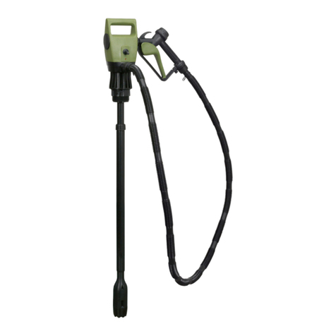
This diesel and fuel oil transfer pump set is intended for use in a wide variety of situations in agricultural, industrial, marine and transport
environments. The pump is available in three versions to cover different voltages : TP97 for 12 volt systems, TP9724 for 24 volt systems and
TP97230 for use where mains power is available. The pump unit can be screwed onto storage containers and tanks and has an integral
priming lever which can also be used in emergencies to deliver small quantities of fuel in the event of power loss. The low maintenance pump
has a high quality, impact resistant housing and built in syphon protection.
Specification .............. TP97 ................ TP9724 ................TP97230
Voltage.......................... 12V .................... 24V ......................... 230V
Frequency...................... n/a ...................... n/a .......................... 50Hz
Current type................... DC......................DC ......... single phaseAC
Power consumption.......14A .................... 10A........................... 1.8A
Performance ................180W..................240W....................... 320W
Delivery.......................38 ltr/m .............. 43 ltr/m................... 52 ltr/m
Max delivery height ...... 9mtr...................10mtr ....................... 15mtr
Weight ......................... 2.5kg .................. 2.5kg ........................2.5kg
General spec.
Temperature of delivery medium................................-10°C to+35°C
Length of suction hose ............................................................ 1.6mtr
Length of delivery hose .............................................................. 4mtr
Suction height......................................................................... Max. 2mtr
Container connection .................................................... G2” and M64x4
Length of connection cable ....................... 2mtr(230V) 3mtr(12/24V)
Protection type ........................................................................... IP24
Noise level............................................................................ 70dB(A)
3. INSTALLATION & ASSEMBLY
3.1 Unpack the product and check that all parts are present with reference to the diagram below. If any items are damaged or missing
contact your Sealey dealer immediately.
1. Pump
housing
2. Priming
hand lever.
3. Dual thread
barrel
connector
4. Suction union
5. Hose clamp
6. Suction hose
9. Standard
nozzle
12. Female
connection
(trigger)
7. Hose clamp
16.Power
cable
14. Delivery
union
15.On/Off
switch
10.Trigger
13.Delivery
hose
11. Male hose
connector
17. Power cable
termination
8. Suction pipe
with filter
3.2 ASSEMBLY. (Refer to fig.1)
3.2.1 Push the suction hose (6) onto
the suction pipe (8) by at least
20mm. Secure the joint with
hose clamp (7).
3.2.2 Cut the suction hose to length
bearing in mind that the pump
may be mounted to more than
one container and that the
filter must be always be under
the surface of the fuel even
when the fuel level is low.
3.2.3 Slide the second hose clamp
(5) over the end of the suction
hose. Push the suction hose
over the suction union on the
pump (4). Slide the hose
clamp up onto the joint and
tighten it.
3.2.4 Assemble the pump to the fuel
container. Firstly feed the
suction hose into the container
until the pump is seated in the
aperture then rotate the pump
so that it screws firmly down
onto the container. The dual
thread arrangement on the
connector will automatically
pick up on either a coarse or
fine thread.
3.2.5 Once mounted the head of the
pump can be rotated into any
position to bring the delivery
union into the ideal orientation
for connection of the delivery
hose.
3.2.6 A rubber washer is attached to
the end of the hose that is
contained within a spring.
Remove the washer and place
it inside the nylon union nut.
Screw the union nut onto the
delivery outlet (14) of the
pump and tighten.
3.2.7 Screw the standard nozzle
assembly (9) onto the male
hose connector (11) on the
free end of the delivery hose.
fig 1
3.2.8 Connect the pump to a suitable power source depending on which model you have. Ensure that the voltage of your pump matches the
voltage of your power source. 230V models will have a mains plug attached. The power cables for 12 & 24V models are terminated with
battery clips (see fig.1 - 17).
3.3 INSTALLATION SITE. It is the responsibility of the owner of the equipment to ensure that the siting of the fuel container and
the installation and operation of the pump is carried out in such a way as to prevent any leakages that that could contaminate
drinking water for people or animals or water courses. The owner should liaise with local authorities, health and safety and
water authorities to ensure that the installation is safe.
Original Language Version TP97, TP9724, TP97230 Issue: 3 - 22/03/10
4. PRIMING & OPERATION
5. MAINTENANCE
4.1 PRIMING OF THE UNIT
 WARNING! NEVER run the pump in an unprimed condition as this will damage the pump and invalidate your warranty.
4.1.1 Before the pump can be used for the first time it must be primed with fuel using the procedure outlined below.
4.1.2 Place the nozzle into an appropriate collecting container and press and hold the trigger.
4.1.3 Operate the manual priming lever until fuel emerges from the nozzle. Release the trigger.
4.1.4 The pump is now ready to be switched on.
4.1.5 If the pump is moved from one container to another it must be reprimed before it can be used again.
4.2 NORMAL OPERATION
4.2.1 Switch on the pump and remove the filler cap from the container or vehicle tank that is to be filled.
4.2.2 Place the nozzle into the tank opening.
4.2.3 Press and hold the trigger until the desired amount of fuel has been dispensed.
4.2.4 Release the trigger, remove the nozzle from the tank and replace the filler cap.
4.2.5 Ensure that the delivery nozzle and hose are safely stowed adjacent to the pump ready for the next delivery.
 DANGER! Clean up any spillage in accordance with regulations governing the handling of diesel fuels.
 WARNING! DO NOT operate the pump unsupervised.
 WARNING! DO NOT allow the pump to run dry. At the end of each delivery the suction filter should always be below the level of the fuel.
 WARNING! DO NOT let the pump deliver for more than 5 minutes against a closed nozzle in order to avoid exceeding the permitted
operating temperature.
 WARNING! Regularly check the delivery hose and connections for damage in order to avoid leakage of fuel.
4.3 EMERGENCY OPERATION
4.3.1 In the event of a power failure it is possible to manually pump very small quantities of fuel using the procedure outlined below.
4.3.2 Place the nozzle into the container or vehicle tank and press and hold the trigger.
4.3.3 Operate the manual priming lever to deliver the fuel.
4.3.4 When the delivery is complete release the trigger and remove the nozzle.
4.3.5 Safely stow the delivery tube and nozzle and replace the filler cap on the container or vehicle tank.
4.4 DEMOUNTING AND REMOUNTING THE PUMP
4.4.1 When demounting the pump in order to place it onto another container or for storage observe the following procedure.
4.4.2 Take suitable precautions to clear up minor spills of fuel that may occur when demounting the pump.
4.4.3 Switch the pump off and disconnect it from the battery or unplug it from the mains power supply.
4.4.4 Before the pump can be unscrewed from the fuel container the delivery hose must be disconnected.
4.4.5 To empty the fuel remaining in the delivery hose firstly place the nozzle into a collection container and hold the trigger open.
4.4.6 Keeping the trigger open begin to loosen the union where the hose is connected to the pump. As the union becomes loose and air
enters the pipe the excess fuel should flow into the container. Keep the disconnected end of the hose at a high level and the container
at a low level so that all the fuel is emptied from the hose.
4.4.7 Unscrew the pump from the threaded connector on the fuel container and slowly remove the pump with the suction hose and filter
attached allowing the fuel to run out completely.
4.4.8 If the pump is then mounted to another fuel storage container it must be primed first before switching on.
4.4.9 If the pump is to be stored even for a short period of time the pump and its hoses should be laid into a clean oil tray in order for all
excess fuel to drain out. The pump and hoses should be cleaned and stored in a well ventilated store suitable for product that handles
fuel.
5.1 The pump has been designed for low maintenance. Should any problems occur return the unit to your local Sealey dealer.
5.2 Clean the entire installation and inspect all piping connections for leaks. Rectify any damage immediately.
5.3 Inspect the filter at the end of the suction tube every time the tank is refilled.
NOTE: It is our policy to continually improve products and as such we reserve the right to alter data, specifications and component parts without prior notice.
IMPORTANT: No liability is accepted for incorrect use of this product.
WARRANTY: Guarantee is 12 months from purchase date, proof of which will be required for any claim.
INFORMATION: For a copy of our latest catalogue and promotions call us on 01284 757525 and leave your full name and address, including postcode.
01284 757500
01284 703534
sales@sealey.co.uk
Sole UK Distributor, Sealey Group,
Kempson Way, Suffolk Business Park,
Bury St. Edmunds, Suffolk,
IP32 7AR
www.sealey.co.uk
Web
email
Original Language Version TP97, TP9724, TP97230 Issue: 3 - 22/03/10
ISSUE DATE 010503
ISSUE NO. 1
DIESEL TRANSFER PUMP
PARTS LIST FOR MODEL NOS:
TP97,TP9724,TP97230
1A 1B 1C
2
3
4
5
6
7
8
9
10
11
NOTE: It is our policy to continually improve products and as such we reserve the right to alter data, specifications and component parts without prior notice.
IMPORTANT: No liability is accepted for incorrect use of this product.
WARRANTY: Guarantee is 12 months from purchase date, proof of which will be required for any claim.
INFORMATION: For a copy of our latest catalogue and promotions call us on 01284 757525 and leave your full name and address, including postcode.
01284 757500
01284 703534
sales@sealey.co.uk
Sole UK Distributor, Sealey Group,
Kempson Way, Suffolk Business Park,
Bury St. Edmunds, Suffolk,
IP32 7AR
www.sealey.co.uk
Web
email
Original Language Version
ITEM PART No. DESCRIPTION
1A 179.23710-930 PUMP 12V WITH CABLE AND CASING
1B 179.23720-930 PUMP 24V WITH CABLE AND CASING
1C 179.23731-930 PUMP 230V WITH CABLE AND CASING
2 179.87988 HANDLE
3 179.87842 SUCTION PIPE
4 179.87994 SUCTION PIPE
5 179.87923 SUCTION FILTER
ITEM PART No. DESCRIPTION
6 179.20156 HOSE CLAMP
7 179.87841 DISCHARGE HOSE
8 179.87840 BREAK PROTECTION SPRING
9 179.87936 HOSE ADAPTOR
10 179.23187 PLASTIC ADAPTOR 1” TO 20MM
11 179.23161 DIESEL DISCHARGE NOZZLE

This manual suits for next models

2

Other Sealey Water Pump manuals

Sealey WPP1750S User manual

Sealey

Sealey WPP1750S User manual

Sealey WPW9355 User manual

Sealey

Sealey WPW9355 User manual

Sealey TP9424.V2 User manual

Sealey

Sealey TP9424.V2 User manual

Sealey wps250a User manual

Sealey

Sealey wps250a User manual

Sealey WPS92A User manual

Sealey

Sealey WPS92A User manual

Sealey SMP60 User manual

Sealey

Sealey SMP60 User manual

Sealey TP17 User manual

Sealey

Sealey TP17 User manual

Sealey TP50.V3 User manual

Sealey

Sealey TP50.V3 User manual

Sealey TP67 User manual

Sealey

Sealey TP67 User manual

Sealey RE83/840.V2 User manual

Sealey

Sealey RE83/840.V2 User manual

Sealey WPD415 User manual

Sealey

Sealey WPD415 User manual

Sealey TP80 User manual

Sealey

Sealey TP80 User manual

Sealey EWP40 User manual

Sealey

Sealey EWP40 User manual

Sealey TP51.V2 User manual

Sealey

Sealey TP51.V2 User manual

Sealey WPC100A.V2 User manual

Sealey

Sealey WPC100A.V2 User manual

Sealey TP6818 User manual

Sealey

Sealey TP6818 User manual

Sealey AK450DX User manual

Sealey

Sealey AK450DX User manual

Sealey AK450DP User manual

Sealey

Sealey AK450DP User manual

Sealey AK4560D.V2 User manual

Sealey

Sealey AK4560D.V2 User manual

Sealey WPD235A.V3 User manual

Sealey

Sealey WPD235A.V3 User manual

Sealey TP6801.V2 User manual

Sealey

Sealey TP6801.V2 User manual

Sealey TP6807 User manual

Sealey

Sealey TP6807 User manual

Sealey WPC100.V2 User manual

Sealey

Sealey WPC100.V2 User manual

Sealey WPC100P User manual

Sealey

Sealey WPC100P User manual

Popular Water Pump manuals by other brands

Wilo NL-HE Series Installation and operating instructions

Wilo

Wilo NL-HE Series Installation and operating instructions

Wacker Neuson PST3 750 Operator's manual

Wacker Neuson

Wacker Neuson PST3 750 Operator's manual

STERWINS 1300 JET SM5I-3 Assemby - Use - Maintenance Manual

STERWINS

STERWINS 1300 JET SM5I-3 Assemby - Use - Maintenance Manual

FLOJET R4515-743 user manual

FLOJET

FLOJET R4515-743 user manual

Teikoku ALP 0104QM instruction manual

Teikoku

Teikoku ALP 0104QM instruction manual

Graco E-Flo SP instructions

Graco

Graco E-Flo SP instructions

a1 cbiss Gastec GV-100S manual

a1 cbiss

a1 cbiss Gastec GV-100S manual

PFT ZP 3 XXL operating manual

PFT

PFT ZP 3 XXL operating manual

Summit CC Installation, operation and maintenance manual

Summit

Summit CC Installation, operation and maintenance manual

Seliger 150L operating instructions

Seliger

Seliger 150L operating instructions

Kessel Aqualift S XL Instructions for installation, operation and maintenance

Kessel

Kessel Aqualift S XL Instructions for installation, operation and maintenance

Giant GP8076 manual

Giant

Giant GP8076 manual

CLIVET WSHN-XEE2 MF 10.2 Installation and operating manual

CLIVET

CLIVET WSHN-XEE2 MF 10.2 Installation and operating manual

Pentair SHURFLO 1100 Series Installation and operation

Pentair

Pentair SHURFLO 1100 Series Installation and operation

Putzmeister BSA 1005 D3B C operating instructions

Putzmeister

Putzmeister BSA 1005 D3B C operating instructions

Bühler technologies CPsingle X1 Installation and operation instructions

Bühler technologies

Bühler technologies CPsingle X1 Installation and operation instructions

WAGNER Unica 4-270 Translation of the original operating manual

WAGNER

WAGNER Unica 4-270 Translation of the original operating manual

GORMAN-RUPP PUMPS 84A3-B Installation, operation, and maintenance manual with parts list

GORMAN-RUPP PUMPS

GORMAN-RUPP PUMPS 84A3-B Installation, operation, and maintenance manual with parts list

manuals.online logo
manuals.online logoBrands
  • About & Mission
  • Contact us
  • Privacy Policy
  • Terms and Conditions

Copyright 2025 Manuals.Online. All Rights Reserved.