Sears STANDARD-FLOW-VALVE-SOFTENER-INSTALLATION User manual

SAVE THIS MANUAL Use plasticbag and tie provided, to hang manualsnearby
the softenerforfuturereference.
WaterSofteners
uSafetyGuides
uUnpacking
uWhereToInstall
uHowToInstall
uPressureTesting
Sears,Roebuck andCo., HoffmanEstates,IL60179 USA
INSTALLATION
MANUAL
Caution:ReadAll
SafetyGuidesBefore
YouStartToInstall
YourSoftener.
If you have questionswhen
installing,operating or main-
taining yoursoftener,and
when setting the timer,call
thistoll--free number...
1--800--426--9345
forsoftenerswith
standardflowvalve
PRINTEDIN U.S.A.

INTRODUCTION
2
Thismanualgivesyouthestepsneededtoinstall
your new Sears Water Softener. To better under-
stand how the water softener is installed, and to
knowwhatyouwillneed,pleasereadthisentire
manual before beginning.
After you have installed the water softener, the
included Owners Manual tells you how to start,
program, operate and maintain it. The owners
manual also has the product warranty, and a
listing of repair parts available from Sears.
Your Sears Water Softener will removehardness
minerals (measured in grains per gallon¼gpg)
andsomeclearwateriron(measuredinpartsper
million¼ppm) from water. See the specifica-
tions, in your owners manual, for the maximum
limits of hardness and iron removal. A water
softener will not improve other water problems
such as acidity, tastes and odors, or iron other
than clear water iron. It will not purify contami-
nated water, or make other unsafe water safe to
drink.
Sears sells a complete line of water treating
equipmenttocorrectvariouswaterproblems.To
be sure you have the proper type and size
equipment, you must have your water tested.
Your Sears store can give you water test results
for hardness, iron and acidity, and tell you what
equipment you need. Simply take at least a 4oz.
sample of your water to Sears, and they will test
it while you wait. If you need help to get your
water tested, or if you have other questions
aboutyourwater,ask atyourSearsstore, orcall
sears Water Line ¼1-800-426-9345.

TABLEOFCONTENTS
3
PAGE
NO.
SECTION1BEFOREINSTALLINGCHECKSANDTESTS
A.SAFETYGUIDES 4
B. UNPACKINGTHEWATERSOFTENER5
C.WATERSYSTEMTESTS6
SECTION2PLANYOURINSTALLATION
A.WHERETOINSTALL THE SOFTENER7
B. TOOLS,PIPE AND FITTINGS, OTHERMATERIALSNEEDED8-9
C.TYPICALSOLDEREDCOPPER(ORCPVC)INANDOUTPIPES 10
D.TYPICALTHREADEDINANDOUTPIPES TOSOFTENER11
SECTION3STEPBYSTEPGUIDESTOINSTALL
A.ASSEMBLEINLET---OUTLETADAPTORS, ORPLASTICBYPASS VALVE12-13
B. INSTALLING3-VALVEBYPASS, ORSINGLEBRASS VALVE14
C.LOCATE ANDCONNECTWATERSOFTENER15
D.CONNECTVALVE ANDSALT TANKDRAIN HOSES 16-17
E.PRESSURETEST—CHECKFORLEAKS 18
F.GROUNDING—CONNECT TOELECTRICALPOWER19-20
RESTART THEWATERHEATER20

BEFOREINSTALLINGCHECKSAND TESTS
SECTION 1
4
1A.SAFETYGUIDES
sReadall steps,guidesandrulescarefullybe-
foreinstallingandusingyournew watersoftener.
Followall stepsexactlytocorrectlyinstall.Failure
tofollowthemcouldcausepersonal injuryor
propertydamage.Readingthisbookwill alsohelp
youto getall ofthebenefitsfromyourwatersoft-
ener.
sYourwatersoftenerwill removehardness min-
eralsand“clearwater” ironfromwater,uptothe
limits shownonthespecificationspageofyour
ownersmanual.Itwill notremoveothertypesof
iron,acids,tastesandodors,etc.Itwill notpurify
pollutedwaterormakeitsafetodrink.
sCheck with yourlocalpublicworksdepartment
forplumbing,electricandsanitationcodes.You
mustfollowtheirguidesasyouinstallyoursoften-
er.
sUseonlyLEAD-FREESOLDERANDFLUX,asre-
quired by FederalandStatecodes,wheninstal-
lingsolderedcopperplumbing.
sProtect thesoftenerand pipingfromfreezing.
Damagefromfreezingvoidsthesoftenerwarran-
ty.Seehowtoprotectfromfreezinginyourowners
manual.
CAUTIONS
PLEASE READANDCOMPLYWITHTHEFOL-
LOWING GUIDESTO PREVENTDAMAGE TO
THESOFTENER OROTHER PROPERTY,
PERSONALINJURY,ORPOSSIBLEFATAL
SHOCK.
sThis softenerworkson24 voltsonly.Be
suretousethetransformerincluded,and
plugitintoa 120Voutlet.
sUnplugthetransformer rightawayifthe
powercableshould becomedamagedor
frayed.Makerepairsbeforepluggingback
intothepoweroutlet.
sAlwaysunplugthesoftener fromelectrical
powerbeforeremoving outervalvecovers.

BEFOREINSTALLINGCHECKSAND TESTS
SECTION 1
5
1B.UNPACKINGTHEWATERSOFTENER
Directions for unpacking the softener are on the
top of the shipping carton. Thismanual, and the
owners manual, were on the small parts card-
board packing piece. You will need the small
partstoinstallthesoftener.Soyoudon’tloseany
parts, keep them on the cardboard piece until
you are ready to use them. Remove all other
cardboard pieces, foam packings, tapes, etc.
from the softener and discard.
Checkthe softenerfor shippingdamage. Ifyou
find damage, report it to your Sears store.
Use care when handling the softener. DO NOT
turn upside-down. DO NOT drop, or set on
sharp objects that could make a hole in the
bottom.Thewatersoftenerisheavyandtoavoid
damage, orpersonal injury, do not try tolift it or
move more than necessary. See page 15, when
you are ready to move it into installation
position.
PARTS DESCRIPTIONS SMALL PARTS
GROUND
CLAMP(2)
TRANSFORMER
GROUNDWIRE,
SCREWS AND
NUTS
TUBE
CLAMPTUBE
ADAPTOR
*PARTSNOTINCLUDED
WITHALL MODELS
INLET--- OUTLET*
TUBE(2)
GROMMET
WASHEROR*
GASKET(2)
INLET--- OUTLET*
NUT(2)
BYPASS VALVE*
CLIP(2)
INLET--- OUTLET*
ADAPTOR(2)
MANUALS

BEFOREINSTALLINGCHECKSAND TESTS
SECTION 1
6
1C.WATERSYSTEMTESTS
Has your water supply had a chemical analy-
sis? Please see page 2.
CHECK YOUR WATER PRESSURE —For your
softener to work right, a water pressure of no
lower than 20 pounds per square inch (psi) is
needed in the house water pipes. The highest
pressure allowed in the water pipes is 120 psi. If
pressure is over 120 psi, buy and install a
pressurereducingvalveinthewaterinletpipeto
the softener.
NOTE:
If water pressure during the day is 100 psi or
more,pressureduringthenightmaygoover120
psi. Adding a pressure reducing valve may
reduce the flow.
If you have a well water system, look at the
pressure gauge to find the water pressure. Call
your local water department if you have city
water.Theywilltellyouwhatthewaterpressure
is where you live.
CHECKYOURWATERFLOWRATE—Awater
flowofatleast3 gallonsperminuteis needed.A
lower flow will keep your softener from work-
ingaswellasitshould.Tomakeaneasycheckof
yourflowrate,dothefollowing. Youwill needa
1 gallon container (can, jar, pail, etc.).
1.Fully open 2 cold water faucets close to the
point water enters the house.
2.With both faucets open, fill the gallon con-
tainer at 1 faucet while looking at a watchor
clock to see how many seconds it takes.
3.Empty the container and go to the second
faucet(besureBOTHfaucetsarestillon).Fill
the gallon container at the second faucet and
see how many seconds it takes.
4.Turn off both faucets. Now add the number
of seconds it took to fill the container atboth
faucets.
5.A total of 90 seconds, or less, means the
system flow rate is good.
FORFUTUREREFERENCE,ENTER RESULTSOFYOUR WATERSYSTEMTESTSINTHE
“FACTS AND FIGURES TOKEEP”TABLEINYOUR OWNERSMANUAL.

PLAN YOUR INSTALLATION
SECTION 2
7
2A.WHERETOINSTALL THESOFTENER
Think of the following points as you choose a
place to put your softener. (see FIG. 1).
·Placeascloseaspossibletothepressuretank
(well water) or water meter (city water).
·Place as close as possible to a water drain
such as a floor drain, laundry tub, sump or
standpipe.
Y· Connect to the house main water pipe BE-
FORE THE WATER HEATER. Temperature
of water going through the softener must
not be more than 120°F (49°C). Hot water
willdamageinnersoftenerparts.Toreducethe
risk of hot water backup, piping between the
softener and water heater should be as long
as possible.
·Keep outside faucets on hard water to save
soft water and salt.
Y· Do not install in a place where the softener
could freeze. Freeze damage voids the war-
ranty by Sears, Roebuck and Co.
Y· Put the softener in a place water damage is
leastlikelytooccurifitdevelopsaleak.Sears
orthemanufacturerwillnotrepairorpayfor
water damage.
Y· A 120V electrical outlet, to plug the trans-
former into is needed within 10 feet of the
softener (the softener has a 10 foot power
cable). Be sure the outlet and transformer
are in an inside place, to protect from wet
weather. Sothesofteneralwayshaselectrical
power, use a continuously “live”outlet, that
cannot be accidentally switched off.
Y· When installing in an outside location, you
must take the steps necessary to assure the
softener, installation plumbing, and wiring,
are as well protected from the elements,
contamination, vandalism, etc., as when
installed indoors.
Y· Keep the softener out of direct sunlight. The
sun’s heat can melt plastic parts.
FIG. 1THE PROPERORDERTO INSTALL WATERTREATINGEQUIPMENT
(Shows sequence ofequipmentonly—seldon,ifever,would all itemsbe needed)

PLAN YOUR INSTALLATION
SECTION 2
8
2B.TOOLS,PIPEANDFITTINGS,OTHERMATERIALSNEEDED
Youmustfirstdecidehowtoruninandoutpipes
to the softener. Look at your house main water
pipeatthepointyouwillconnectthesoftener.Is
the pipe soldered copper, glued plastic, or
threaded galvanized or brass? What is the pipe
size? What kind of pipe and fittings is it easiest
for you to work with, and what tools do you
have?
Now look at the common plans for in and out
piping on pages 10 (soldered copper) and 11
(threaded). Select the drawing best for you and
use it as a guide to plan what materials you will
need. As you plan your in and out piping, keep
in mind thefollowing check list. Then get allthe
materials you will need before you start.
NOTE:
Use page 9 to make a plan drawing for your
specific installation.
Some models may include a plastic bypass
valve, an installation kit and a length of drain
tubing.
4In and out pipes to the softener must be at
least 3/4 in. size. Some local codes may tell
youtousenolessthan1in.pipesize(seeNote
on pages 10 or 11). You should maintain the
same, or larger, pipe size as the water supply
pipe, up to the softener inlet and outlet.
4Usecopper,brass,orgalvanizedpipeandfit-
tings.Somecodesmayalsoallow CPVCplas-
tic pipe.
4Copper and galvanized pipe corrode fast
when connected together. Use pipe and fit-
tings of the same material.
4You can buy adaptors to go from a copper or
threadedmainwaterpipetoCPVCinandout
pipe.
4Sears has kits and bypass valves you can buy
to help make installing your softener easier.
See pages 10 and 11.
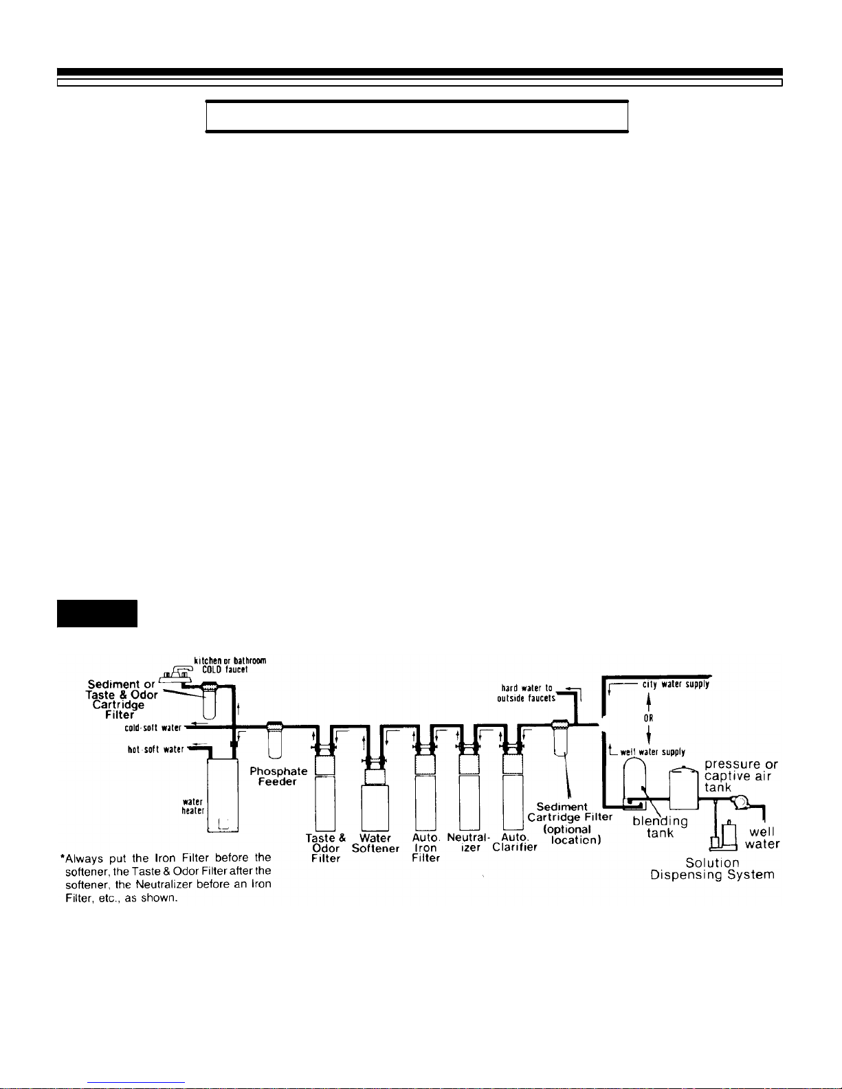
4ALWAYS install a bypass valve or valves. Ei-
theruse 3shut-offvalves,or1of Searsspecial
valves.Bypassvalvesletyouturnoffwaterto
the softener if needed to make repairs, but
still have water in the house pipes.
4Drain tubing (3/8 in. inside diameter) is
needed for valve and salt tank drains. See
steps 1 and 2 on pages16 and 17. Somemod-
els include a length of drain tubing, or you
can buy it at most Sears stores.
Ifarigidvalvedrainisneededtocomplywith
plumbing codes, you can buy the partsneed-
ed(seepage16)tochangethesoftenertoa1/2
in. copper tubing drain.
4TOOLS NEEDED:—Common and cross
point(Phillips)screwdrivers, slip jointpliers
and a tape measure or rule. ALSO¼
¼for SOLDERED COPPER —tubing cutter,
propanetorch,solid-coreLEAD-FREEsolder,
paste flux, emery cloth, sandpaper or steel
wool.
¼for THREADED PIPE —hacksaw or pipe
cutter, pipe wrenches, pipe threading tool,
pipejointcompoundapprovedforuseonpo-
table water.
¼forCPVCPLASTIC—hacksaw,adjustable
wrench, solvent cement approved for use on
potable water, primer.

PLAN YOUR INSTALLATION
SECTION 2
9
2B.PIPEANDFITTINGS,PLANDRAWING

PLAN YOUR INSTALLATION
SECTION 2
1
0
2C.TYPICALSOLDEREDCOPPER(ORCPVC)INANDOUTPIPESTOSOFTENER
FIG. 2
*NOTE:
For1in.plumbingconnection,buy2sweat
adaptors(1in.femalethreadx1in.sweat)and
plumbdirectlytotheinlet---outletadaptorsorby-
passvalve.Threadsontheinlet---outletadaptors
and bypass valveare 1 in.pipethread.Donot
usetheinstallationkit,SearsStockNo.42---3441,
ortheflexibleconnectors,SearsStock No.
42---34401.
CAUTION:
DOALL SOLDERINGBEFORECONNECT-
INGSWEATADAPTORTOINLET---OUTLET
ADAPTORSORBYPASS VALVE.
SEARSKITSANDVALVESTOMAKE
INSTALLINGYOUR SOFTENEREASIER
1BYPASS VALVE(Plastic)
SearsStock No.42---3437
(includedwithsomemodels)2BYPASS VALVE(Brass)
SearsStock No.42---3436
One,easyworkingvalvetakestheplaceof3separatevalves.
3INSTALLATIONKIT
SearsStock No.42---3441
(includedwithsomemodels)
USE AS SHOWNIN,
ORTOREPLACETHE
1²X3/4²SWEAT
ADAPTORSINAND.
CONNECTFROMIN-OUT
PIPES,ATDOTTEDLINE,
DIRECTLYTOTHEINLET
ANDOUTLETADAPTORS
ORTOBYPASS VALVE¡.
SEE , , AND.
FLEXIBLECONNECTORS
SearsStock No.42---34401
Allowseasyhookupeven
ifpipesarenote exactly
aligned.
(CHECKLOCALPLUMBINGCODES)
D
ABC
C
AB
o--ring
nut
coppertube

PLAN YOUR INSTALLATION
SECTION 2
1
1
2C.TYPICALTHREADEDINANDOUTPIPESTOSOFTENER
FIG. 3
*NOTE:
For1in.plumbingconnec-
tion,usea1in. threaded
straightconnector.
DNOTE:
If you are planning a threaded plumbing instal-
lation, with a 3-valve bypass, use Fig. 2 A as a
guide. Use union fittings, as needed, to connect
the plumbing.

STEP BY STEP GUIDES TO INSTALL
SECTION 3
1
2
3A.ASSEMBLEINLET---OUTLETADAPTORS,ORPLASTICBYPASS VALVE
1.Close the shut-off valve on the house main
water pipe, near the water meter or pressure
tank, to turn off the water.
2.Shutoffthegasorelectricsupplytothewater
heater.
3.Openthehighestand lowestwaterfaucetsin
your house to let water drain from the pipes.
Close faucets after water has drained.
4.If not already done, remove all cardboard or
plasticpackingpieces frominside thesoften-
er. Set the cardboard liner (with parts for
installingfastenedtoit)whereyoucaneasily
see it, and get to parts as you need them.
Removethesalt
holecover------ lift
straightupward,
andthemaincover
------ pull outward
on2tabstore-
lease.Setboth
coversasideso
theywill notget
scratchedorbro-
ken.
5.INSTALL THE INLET AND OUTLET
ADAPTORS OR SEARS BYPASS VALVE.
STOCK NO. 42-3437 (FIG. 4, 5 AND 6).
NOTE:
If you will install the bypass valve (use follow-
ing steps a and c), the adaptors are not used. If
youdonotinstallthebypassvalve,youmustuse
the adaptors (use following steps a and b).
a.Visuallycheckandremoveanyforeignmate-
rials from the valve inlet and outlet ports
(FIG. 4).
b.INLET AND OUTLET ADAPTORS (Adap-
tors and clips are on the cardboard liner).
Push the adaptors into the valve inlet and
outlet ports as far as they will go. Bothadap-
tors are the same and fit either valve port.
Snap the 2 large holding clips into place,
from the top down as shown.
CAUTION¼Be sure the clips snap firmly
into place so the adaptors will not pull out.
GO TO PAGE 14.
c.BYPASS VALVE STOCK NO. 42-3437
—If not already done, put a light coating of
silicone grease or Vaseline on the bypass
valve o-rings.
Pushthebypassvalveintothesoftenervalve
as far as it will go. Snap the 2 large holding
clips into place, from the top down as
shown.
CAUTION¼Be sure the clips snap firmly
into place so the bypass valve will not pull
out.
GO TO PAGE 15.

STEP BY STEP GUIDES TO INSTALL
SECTION 3
1
3
3A.ASSEMBLEINLET---OUTLETADAPTORS,ORPLASTICBYPASS VALVE
FIG. 4INSTALLING INLET-OUTLET
ADAPTORSORBYPASS VALVE
NOTE:
The softener includes either theadaptors, or the
bypass valve, depending on the model.
ELECTRONICDEMANDMODELSONLY
Besuretheturbineandsupportarefirmlyin
placeinthevalveoutlet.
FIG. 5INSTALLINGHOLDINGCLIP
FIG. 6BYPASS VALVE TURNED
DOWNWARD

STEP BY STEP GUIDES TO INSTALL
SECTION 3
1
4
3B.INSTALL 3---VALVEBYPASS,ORSINGLEBRASS BYPASS VALVE
1.INSTALLING 3 VALVE BYPASS, OR
SEARS BYPASS VALVE, STOCK NO.
42-3436, AND PIPES (FIG. 7)
a.Cut the house main water pipe where you
willconnectthesoftener.Loosely puttogeth-
erpipe,fittings,andthe3valvesorSearsspe-
cial bypass valve. Place valve(s) within easy
reach.
IMPORTANT:
When looking at the front of the softener, the
inlet is on the right side. If water in your house
mainwaterpiperunsfromlefttoright,besureto
use a “cross-over”as shown on page 9.
b.When all pipe, fittings and valves make a
good fit together, tighten all threaded joints
(usepipedopeonoutsidethreads),orsolder.
FIG. 7BYPASS VALVES

STEP BY STEP GUIDES TO INSTALL
SECTION 3
1
5
3C.LOCATESOFTENERANDCONNECTPIPES
1.MOVE THE SOFTENER INTO PLACE
Movethesoftenerintoplace,ontoaleveland
smoothsurface.Ifneeded,putapieceof3/4²
plywood, at least 17²x 20², under the tank.
Then putspacers under the plywood tolevel
the softener. Do not put shims or spacers
directly under the tank, without the ply-
wood. The weight of the softener, when full
of salt and water, may cause the tank to
puncture or break at the shim or spacer.
Tomovethesoftener,gripundertheridgeonthe
salt tank sidewall and carefully rock back and
forth, into position.
2.CONNECT THE SOFTENER (Refer to your
plandrawingonpage9, andtopage10 or11.
Read the IMPORTANT note on page 14.
Then, measure, cut (thread if needed) and
put all pipe and fittings together up to the
main water pipe, or to the bypass valve(s)
you installed on page 14.
NOTE:
a.Include adaptors, reducers, union fittings,
*flexible connectors, installation kit, etc., as
needed.
b.Cut pipe lengths exact for correct aligning,
and to prevent stress on the softener valve.
c.Use pipe joint compound or Teflon tape on
outside pipe threads.
d.When all piping fits together¼
¼solder all sweat fittings.
¼prime and cement all CPVC joints.
¼tighten all threaded joints.
CAUTIONS:
YNever solder fittings while connected to
non-metallic parts. Wait until soldered pipe has
cooled before connection (see fig. 8).
YBe very careful when putting pipe fittings
onto the plastic threads of the softener adap-
tors, or the bypass valve. Do not cross thread,
and do not overtighten.
FIG. 8TYPICALSOLDERINGCONNEC-
TION
*Flexibleconnectorsarenotallowedinall areas.CHECKYOURLOCALCODES.

NOTE:Overflow
draintubingis
availablefrom
Sears,ItemNo.
42---3433 (20 ft)
grommettube
adaptor
tube
clamp
overflowdrain
tubing(see step2,
topofpage 17)
valvedrain hose
(see step1,above)
tieorwire
tubinginplace
tube
clamp
drain
fitting
Todrainpoint
otherthan
floordrain.
Support tubing
inplaceas
needed.
STEP BY STEP GUIDES TO INSTALL
SECTION 3
1
6
3D.CONNECTVALVEANDSALT TANKDRAINS
1.CONNECT THE VALVE DRAIN TUBING
Take a length of 3/8²inside diameter (I.D.)
drain tubing and attach 1 end to the drain
fitting (FIG. 9). Use a tube clamp to hold it in
place. Put the other end of the tubing over a
floor drain, into a laundry tub, standpipe, or
othersuitabledrain.Checkyour localcodes.
IMPORTANT: (see FIG. 9)
YLeave an air gap of about 1-1/2²between the
end of the tubing and the drain. This gap is
needed so you don’t get a back-flow of sewer
waterintothesoftener.Do not puttheendofthe
tubing into the drain or connect without the air
gap.
YPlace and support the tubing so it does not
kink or have sharp bends. So water pressure
doesnotcausethetubingto“whip”,tieorwireit
in place. Do not pinch the tubing shut. The
softener will not work if this drain tubing is
pinched, plugged, closed or restricted in any
way.
FIG. 9DRAINTUBING
YKeep the tubing lower than the drain fitting.
(In some homes, to get to a drain you must raise
the tubing and run it over-head. If you need an
overhead drain, do not raise the tubing more
than 8¢ above the floor. A copper drain tube is
best to use.)
COPPER DRAIN TUBE: The plumbing codes
where you live may say that you must use a
copper valve drain tube. A copper tube is also
best to use for an over-head drain. Use acopper
drain tube if the softener is installed outside, or
in the sunlight. Heat from the sun makes many
kinds of rubber or plastic hose to soften, flatten
and close up.
Toadaptacopperdraintubetothesoftener,usea
hacksaw to cut the barbed end from the drain
fitting as Fig. 10 shows. Buy a compression
fitting(1/4in.femalepipethreadsx1/2in.O.D.
tube) and tube from your local hardware store.
FIG. 10 COPPER DRAINTUBE

STEP BY STEP GUIDES TO INSTALL
SECTION 3
1
7
3D.CONNECTVALVEANDSALT TANKDRAINS
2.CONNECT SALT TANK OVERFLOW
TUBING
a.Take the rubber grommet, tube adaptor and
tubeclamp(FIG.9)thatareonthesmallparts
cardboard liner.
b.Push the grommet into the hole in the salt
tank wallso half isinside and half is outside.
c.Push the bigger end of the tube adaptor into
the grommet.
d.Push one end of a length of 3/8²I.D. tubing
onto the tube adaptor, using the tube clamp
to hold it in place. Put the other end of the
tubing over the floor drain.
IMPORTANT:
·Thesalttankoverflowisforsafetyonly.Ifthe
salt tank should overfill with water, the
overflow tubing carries it to the drain.
·Over-fillwatermustrundownwardthrough
the tubing. Do not raise the tubing higher
than the grommetand tube adaptor (FIG.9).
·Do not connecttothevalvedrain tubingyou
installed in step 1. Both drains must have a
separate length of tubing.

STEP BY STEP GUIDES TO INSTALL
SECTION 3
1
8
3E.PRESSURETEST--- CHECKFORLEAKS
TESTING YOUR PLUMBING WORK FOR
WATER LEAKS.
CAUTION:
To avoid water or air pressure damage to
softener inner parts, and to flush pipe chips or
other residue from the water pipes, be sure to
do the following steps exactly as instructed.
LookatthepictureinFIG.12showing yourkind
of bypass valve(s).
1.Fully open 2 cold, soft water faucets nearby
the softener.
2.Place bypass valve(s) in “bypass”position.
On a single valve, slide the stem into BY-
PASS.Ona3-valvesystem,closetheinletand
outlet valves and open the bypass valve.
3.Fullyopenthehousemainwaterpipeshutoff
valve. Observe steady water flow from both
open faucets.
4.Place bypass valve(s) in “service”,EXACTLY
as follows: Keep soft water faucets open.
a.SINGLEBYPASSVALVE:SLOWLY,slidethe
valve stem toward service, pausing several
times to allow the softener to pressurize
slowly.
b.3-VALVE BYPASS: Fully close the bypass
valve and open the outlet valve. SLOWLY,
opentheinletvalve, pausingseveraltimesto
allow the softener to pressurize slowly.
5.After about 3 minutes, open a hot water
faucet for about 1 minute, or until all air is
expelled, then close.
6.Close both cold water faucets.
7.Check your plumbing work for leaks and fix
right away if any are found. Be sure to
observe previous caution notes.
FIG. 11 HOUSE MAINWATERSHUTOFF
VALVES
FIG. 12 BYPASS VALVE(S) SOFT WATER
SERVICE/HARD WATERBYPASS
Bypassvalve(s)shouldalwaysremaininsoft
waterservice position.Position in“bypass”
onlyifneeded forsoftener repairs.

STEP BY STEP GUIDES TO INSTALL
SECTION 3
1
9
3F.GROUNDING,CONNECT TOELECTRICALPOWER
1.INSTALLGROUNDINGWIREBETWEEN
THE SOFTENER IN AND OUT PIPES
Thehousecoldwaterpipe(ironor copper) is
often used to ground all electrical outlets in
the home. Outlets are grounded to protect
you from shock when you touch any electric
appliance plugged into the outlet. If you
didn’t install a 3-valve bypass, or a brass
single bypass valve (FIG. 12), the cold water
pipe ground is broken.
FIG. 13 COLDWATERPIPE GROUND
Torestoretheground,taketheclamps(2),screws
(2), nuts (2) and ground wire that are on the
cardboard liner. Install across the iron or copper
in and out pipes as shown in FIG. 13. Be sure
good contact is made between the pipe and the
clamps. Fasten the ground wire tightly between
the clamps.
FIG. 14 WATERMETERJUMPERWIRE
IMPORTANT:
Be sure the cold water pipe has direct metal to
metal contact all the way to the ground. Plastic,
rubberorotherelectricallyinsulatingpartssuch
as hoses, fittings, washers or gaskets can break
the direct metal to metal contact. Also check the
water meter (city water) or the well pump.
Install #4 copper jumper wires, clamped tightly
on both ends, across insulated parts (FIG. 14).
2.ELECTRICAL POWER OUTLET FOR
YOUR SOFTENER
The softener works on 24 volt, 60 Hz electric
power. The included transformer changes
standard 120 volt AC house power to 24
volts. You must plug the transformer into a
120 volt outlet only. Be sure the outlet is
always “live”so someone cannot turn it off
by mistake.
NOTE:
The included transformer is made for inside use
only. Be sure the electrical outlet you plug the
transformerintoisinside,toprotectfromweath-
er (see page 7).

STEP BY STEP GUIDES TO INSTALL
SECTION 3
2
0
7159931 (Rev.2/98)
3F.CONNECT TOELECTRICALPOWER
3.FASTEN THEPOWERCABLE ANDPLUG
IN THE TRANSFORMER
Looking at FIG. 15, fasten the 2 power cable
lugs (1 under each screw) to the transformer
asshown.Tightenbothscrews.Thenplugthe
transformer into the electrical outlet.
FIG. 15 CONNECTINGTRANSFORMER
INSTALL COVERS
After installing your water softener, replace the
covers. First, position the main covers on the
softener. Then, set the salt hole cover into the
main cover, as shown, and lower closed.
RESTART THEWATER HEATER
TURN ON THE GAS (OR ELECTRIC) SUPPLY TO THE WATER HEATER AND LIGHT THE PILOT.
NOTE:
Your new Sears softener is now softening the
waterforyourhouseholdneeds.However,your
WATER HEATER is filled with hard water. To
have fully soft water right away, you can drain
thewaterheatersoitrefillswithsoftwater,ifyou
don’t drain it, it will take a few days before you
have fully soft water.
Todrainthewaterheater,openahotwaterfaucet
and let it run until the water runs cold. Then
close the faucet.
YOURPLUMBINGANDELECTRICALWORKISCOMPLETE.Nowgoto yourownersmanualand
do the softener start-up steps¼setting the timer, filling the storage tank with salt, sanitizing, etc.
Table of contents
Other Sears Water Dispenser manuals
Popular Water Dispenser manuals by other brands

BRIO
BRIO CLPOU320UVF3 Setup manual

Bunn
Bunn Soft Heat Server Installation & operating guide

Everpure
Everpure Ever Plus ESO 6 Specifications

Haws
Haws 3202G Installation, operation & maintenance instructions

Toshiba
Toshiba RWF-W1669BF(W) instruction manual

Kenmore
Kenmore Elite IntelliSoft 625.384260 owner's manual

GE
GE Appliances Profile GXCF35GBS owner's manual

DTE
DTE CoolMaster K1 Series operating manual

Hellenbrand
Hellenbrand Water Conditioning System H-125 Series owner's manual

Water Depot
Water Depot PLATINUM SERIES owner's manual

NESTLE
NESTLE ReadyRefresh Lumina user guide

BWT
BWT Perla Silk S Installation and operating manual