manuals.online logo
Brands
  1. Home
  2. •
  3. Brands
  4. •
  5. Sears
  6. •
  7. Water System
  8. •
  9. Sears 625.347030 User manual

Sears 625.347030 User manual

Other Sears Water System manuals

Sears 625.340281 User manual

Sears

Sears 625.340281 User manual

Sears Craftsman 390.252151 User manual

Sears

Sears Craftsman 390.252151 User manual

Sears WaterWorks RO 2000 Guide

Sears

Sears WaterWorks RO 2000 Guide

Sears 390.250095 User manual

Sears

Sears 390.250095 User manual

Sears Craftsman 390.250097 User manual

Sears

Sears Craftsman 390.250097 User manual

Sears CRAFTSMAN 390.252157 User manual

Sears

Sears CRAFTSMAN 390.252157 User manual

Popular Water System manuals by other brands

Accu-Tab PowerBase 3070AT Installation and operating instructions

Accu-Tab

Accu-Tab PowerBase 3070AT Installation and operating instructions

Energy Plus VTS30HP Manual of installation and use

Energy Plus

Energy Plus VTS30HP Manual of installation and use

Spirotech SPIROVENT SUPERIOR S250 user manual

Spirotech

Spirotech SPIROVENT SUPERIOR S250 user manual

Culligan Aqua-Cleer Aqua-Cleer Advanced Drinking Water... owner's guide

Culligan

Culligan Aqua-Cleer Aqua-Cleer Advanced Drinking Water... owner's guide

A.O. Smith Dura-Max AJH - 1000A - P instruction manual

A.O. Smith

A.O. Smith Dura-Max AJH - 1000A - P instruction manual

Microline T.F.C.-4 Installation, operation & service manual

Microline

Microline T.F.C.-4 Installation, operation & service manual

Eureka Forbes Aquaguard Select user manual

Eureka Forbes

Eureka Forbes Aquaguard Select user manual

Cetetherm AquaEfficiency Quick installation guide

Cetetherm

Cetetherm AquaEfficiency Quick installation guide

CB Tech CB-VOC installation guide

CB Tech

CB Tech CB-VOC installation guide

Vaillant auroFLOW plus VPM 15 D Installation and maintenance instructions

Vaillant

Vaillant auroFLOW plus VPM 15 D Installation and maintenance instructions

resideo Braukmann HS10S installation instructions

resideo

resideo Braukmann HS10S installation instructions

Gude INOX 100/24 manual

Gude

Gude INOX 100/24 manual

Mono Eco 1-60 Installation, operation and maintenance instructions

Mono

Mono Eco 1-60 Installation, operation and maintenance instructions

SpectraPure Drinking Water Kit instructions

SpectraPure

SpectraPure Drinking Water Kit instructions

HydroCare Dual Action Installation, use & care guide

HydroCare

HydroCare Dual Action Installation, use & care guide

Alpha SolarSmart 150 Installation and servicing instructions

Alpha

Alpha SolarSmart 150 Installation and servicing instructions

TA FRISTAR3 operating manual

TA

TA FRISTAR3 operating manual

GÜDE HWA 800 K manual

GÜDE

GÜDE HWA 800 K manual

manuals.online logo
manuals.online logoBrands
  • About & Mission
  • Contact us
  • Privacy Policy
  • Terms and Conditions

Copyright 2025 Manuals.Online. All Rights Reserved.

__ARS
OWNERS
MANUAL
MODEL NO.
625.347030
SAVE THIS MANUAL_:
UNIVERSAL
Undersink Reverse Osmosis
HOME DRINKING
WATER SYSTEMS
HOW TO INSTALL
HOW IT WORKS
CARE OF
REPAIR PARTS
PRINTED IN U.S,A.
TABLE OF CONTENTS
Safety Guides ............................................... .2-3
What Your Home Drinking Water System Will Do ..................... 3
Things To Check Before You Start To Install ....................... 4-5
How To Install Your Home Drinking Water System .................. 5-9
How Your Home Drinking Water System Works ................... 9-10
Care Of Your Home Drinking Water System ..................... 10-14
Remote Location For The RO .................................... 14
Dimensions And Specifications ................................. ;.. 15
Repair Parts ............................................... 16-17
WARRANTY
FULL WARRANTY ON SEARS HOME DRINKING WATER SYSTEM
(except filter, filter cartridge or membrane)
For one year from the date of purchase, when this home drinking water system is installed and
maintained in accordance with our instructions, Sears will repair, free of charge, defects in material
and workmanship, except for disposable filters, cartridges and membranes.
TO OBTAIN WARRANTY SERVICE, SIMPLY CONTACT THE NEAREST SEARS SERVICE
CENTER THROUGHOUT THE UNITED STATES. This warranty applies only while this product
is in use in the United States.
This warranty gives you specific legal rights, and you may have other rights which vary from state
to state.
Sears, Roebuck and Co., Dept. 731-CR-W, Sears Tower, Chicago, IL 60684
SEARS INSTALLATION POLICY
All installation labor arranged by Sears shall be per-
formed in aneat, workmanlike manner in accordance
with generally accepted trade practices. Further, all
installations shall comply with all local laws, codes,
regulations and ordinances. Customer shall also be
protected, during installation, by insurance relating
to Property Damage, Workman's Compensation and
Public Liability.
SEARS INSTALLATION WARRANTY
In addition to any warrranty extended to you on the
Sears merchandise involved, which warranty
becomes effective the date the merchandise is in-
stalled, shouldthe workmanshipof any Sears arrang-
ed installationprovefaultywithin one year, Sears will,
upon notice from you, cause such faults to be cor-
rected at no additional cost to you.
ISAFETY GUIDES I
Read all steps, guides and rules carefully
before installing and using your Home Drink-
ing Water System. Follow all steps exactly to
correctly install. Reading this book will also
help you to get all the benefits from your Home
Drinking Water System.
_, DO NOT A'I-I'EMPT TO USE THIS PRODUCT
TO MAKE SAFE DRINKING WATER FROM
!SAFETY GUIDES
NON-POTABLE WATER SOURCES. DO NOT
USE THE SYSTEM ON MICROBIOLOGICAL-
LY UNSAFE WATER, OR WATER OF
UNKNOWN QUALITY.
_CHECK WITH YOUR LOCAL PUBLIC
WORKS DEPARTMENT FOR PLUMBING
AND SANITATION CODES. YOU MUST
FOLLOW THEIR GUIDES AS YOU INSTALL
THE SYSTEM. FOLLOW YOUR LOCAL
CODES IF THEY DIFFER WITH GUIDES IN
THIS MANUAL.
The Home Drinking Water System works on
water pressure of 40 psi (minimum) to 125 psi
(maximum). See the table on page 15. If your
house water pressure is over the maximum,
install a pressure reducing valve in the water
supply to the Home Drinking Water System.
Do not install the Home Drinking Water System
outside, or in extreme hot or cold temp-
eratures. Temperature of the water supply to
the Home Drinking Water System-must be be-
tween 40°F (minimum) and 100 °F (maximum).
See the specification table on page ! 5 .DO
NOT iNSTALL ON HOT WATER.
Read the other limits (pH, hardness, etc.) on
page 15 and be sure your water supply con-
forms. Please read WATER SUPPLY, page 4.
WHAT YOUR HOME DRINKING WATER SYSTEM WILL DO
Your Home Drinking Water System is a REVERSE
OSMOSIS (RO) water treating unit. It uses
household water pressure to reverse a natural
physical process called osmosis. Water, under
pressure, is forced through a semi-permeable mem-
brane where minerals and impurities are screen-
ed out and sent down the drain with the waste
water. These minerals and impurities are measured
as total dissolved solids (TDS).
The system includes replaceable pre and posffilter
sediment-carbon cartridges. The prefllter removes
sand, dirt, rust particlesand other sediments. Italso
takes chlorine out of the feed water. The postfilter
removes any remaining_tastes and/or odors just
before water is taken from the system faucet. The
storage area holds almost 1 gallon of RO product
water for your needs.
The undersink system connects to a house COLD
water pipe for a water supply. An automatic shutoff
valve prevents water waste when the storage area
is full and the faucet is closed.
The drinking water system gives you a continuous
supply of sparkling clear, delicious water for drink-
ing and cooking. Foods will look better and taste
better too. The system eliminates the need to buy
bottled water. Instead, it puts high quality water right
at your fingertips.
NOTE: A product data sheet is included, and also
available from Sears. The data sheet lists what this
RO system will remove (or reduce) from the water.
ELECTRONIC MONITOR (OPTIONAL*)
The electronic model has 2 water quality sensors,
located in the electronic box. Indicator lights on the
faucet base work with the se_nso_'s,or probes, to
show you when water quality is good, and when the
system needs servicing.
As you=takewater from the RO faucet, a flashing
green light means the system is giving you high
quality RO water. Over a period of time, the RO
membrane, prefilter cartridge and posffilter begin
to lose efficiency. Rashing amber lights(see pages
10, 11 and 12)tell youwhen to service the RO mem-
brane and filters.
*An electronic monitor kit is available from Sears,
Stock No. 42-34704.
I
THINGS TO CHECK BEFORE YOU START TO INSTALL
• PARTS IN THE SHIPPING CARTON -- Unpack
the carton carefully so needed parts are not discard-
ed by mistake. Included are:
RO
,_ASSEMBLY WATER
SUPPLY
SADDLE
VALVE
1WASTE
', IWATER
II I DRAIN
IICLAMP
,,
TOP COVER
C
\X',
FAUCET
ASSEMBLY
• WATER SUPPLY -- The cold water supply to
your Home Drinking Water System must be within
certain chemical limits (see page 15). If not, it will
not make product water as it should, and life of the
RO membrane is shortened. Trained salespeople
at Sears can arrange for afree water analysis. This
analysis will tell you if the water needs other treat-
ment before it goes into the Home Drinking Water
System,
CAUTION: CHLORINE IN WATER SUPPLY. The
RO membrane is destroyed by chlorine. A pre-
filter carbon cartridge removes chlorine from the
water before it enters the RO membrane.
IMPORTANT: TO KEEP CHLORINE FROM
DESTROYING THE RO MEMBRANE, BE SURE
TO REPLACE THIS CHLORINE REMOVAL CAR-
TRIDGE AT LEAST EVERY 6 MONTHS, OR 900
GALLONS. (SEE RO CARE GUIDE, PAGE 14.)
• WHERE TO MOUNT THE RO ASSEMBLY AND
LOCATE THE STORAGE TANK --
The Home Drinking Water System fits nicely under
the kitchen or bathroom sink. However, you can in-
stall it where most handy for you. You do need a
COLD water supply pipe and drain point within 6
feet. Where space is limited, you can lay it on a shelf
or floor. Locate the assembly so you can easily get
to it to change filters.
The RO System weighs about 40 Ibs. when full of
water. Set it on the floor or other solid surface that
will hold this weight.
(SINK TRAP) WATER SUPPLY ASSEMBLY
4
ITHINGS TO CHECK BEFORE YOU START TO INSTALL
REMOTE LOCATION -- You can install the RO
assembly or water supply saddle valve in another
place away from the RO faucet (please see page
14).
•REPLACING ANOTHER RO SYSTEM -- We
suggest you remove all parts of another RO system,
and use everything included with your new RO
system.
FTOOLS AND MATERIALS YOU WILL NEED
•7/16" and 1/2" open end wrenches
•pliers and adjustable wrench
•slotted and Phillips head screwdrivers
•plumbers putty
•pipe joint compound (tread seal) or teflon tape,
approved for use on potable water supplies
•hand or battery powered drill with 1/8" and 1/4"
bits (if needed for the cold water supply saddle
valve, below, and for the drain clamp, page 6)
•electric drill and bits, if hole is needed for the
RO faucet, page 7
CAUTION: TO AVOID DAMAGING ASINK
BEYOND REPAIR, CONSULT A QUALIFIED
PLUMBER OR INSTALLER FOR GUIDES
BEFORE DRILLING HOLES IN PORCELAIN OR
STAINLESS STEEL.
tHOW TO INSTALL YOUR HOME DRINKING WATER SYSTEM I
STEP 1 -- INSTALL THE COLD WATER SUPPLY SADDLE VALVE (FIG. 2)
•Install this valve on the COLD water pipe to the
kitchen sink (FIG. 2).
•This valvehas a cuttingpin and willmake itsown
hole in copperor plastic pipe. To installon iron pipe,
you have to drill a 1/8" diameter hole for the cut-
ting pin.
DANGER (IF DRILLING PIPE): TO PROTECT
YOURSELF FROM SERIOUS INJURY OR FATAL
SHOCK, USE A HAND OR BATTERY POWERED
DRILL ONLY TO MAKE THE HOLE, DO NOT USE
AN ELECTRIC DRILL.
•USE THE FOLLOWING GUIDES TO INSTALL:
1. Close the house main water supply valve. Open
a high and low faucet in the house to drain water
from the pipes.
2. Looking at FIG. 2, if not already done, turn the
valve into clamp A and tighten. Turn the valve han-
dle all the way out.
VALVE
C_MPB
HANDLE
HOW TO INSTALL YOUR HOME DRINKING WATER SYSTEM
continued from page 5
NOTE: If you have to drill a 118" diameter hole, hold
the valve with clamp A up to the pipe and mark the
spot to drill. BEFORE DRILLING, READ THE
DANGER NOTE ON PAGE 5.
3. Place the seal on the inside of clamp A as shown.
Locate clamp A (turn handle in to align pin if pre-
drilled hole) and clamp B on the pipe. Fasten in
place using 2 screws. Tighten each screw evenly,
but do not overtighten and crush the pipe.
4. Turn the valve handle inward to make a hole in
the copper or plastic pipe.
DO NOT TURN ON THE WATER SUPPLY AT THIS
TIME.
NOTE: BE SURE THE VALVE HANDLE PACKING
NUT IS TIGHT.
STEP 2 -- INSTALL THE DRAIN CLAMP (FIG. 3)
•The drain clamp fits up to 1-3/4" diameter drain
pipe.
•The best place to install the clamp is...
A. about 3" above the standing water level in the
sink p-trap (drawing A).
B. on the horizontal drain pipe run of a double bowl
sink (drawing B).
•Locate so drain tubing from the faucet (FIG. 5)
makes a straight run to the clamp, without any
dips, loops, low spots , or kinks.
•You have to drill a 1/4" diameter hole for the sad-
dle clamp.
•Use the following guides:
1. Remove the paper backing from the gasket and
place the sticky side of the gasket into the recess-
ed area of the clamp body.
DRAIN CLAMP
CHECK LOCALI
CODES FOR
APPROVAL
CLAMP BODY
DRILL 1 4" DIA. HOLE
(RUN DRILL BIT THROUGH
HOLES IN CLAMP BODY
AND GASKET.)
WING
NUT
2. Place the U-bolt around the drain pipe and slide
the clamp body onto the bolt.
3. Turn the 2 wing nuts onto the U-bolt and tighten
snugly, BUT DO NOT OVERTIGHTEN AND
BREAK THE BODY OR CRUSH THE DRAIN PIPE.
4. Using a hand or battery powered 114"ddll, make
a holein the drain pipe by goingthrough the thread-
ed fitting onthe clamp body (READ THE DANGER
NOTE ON PAGE 5).
NOTE: Be sure the pipe is clean and smooth where
the gasket will seal. 6
HOW TO INSTALL YOUR HOME DRINKING WATER SYSTEM
STEP 3 -- PREPARE MOUNTING HOLE, ASSEMBLE FAUCET AND INSTALL
A. PREPARE MOUNTING HOLE.
1. Pick I of the following places for the faucet where
it willfit flat against the surface. Be sure you have
room underneath for the tubing connections (FIG.
5, page 8).
•.. in a hole already in the sink (enlarge to 1-1/4"
diameter if needed) to use for an extra faucet
or spray.
...drill a hole (1-1/4" diameter) in the sink top.
BEYOND REPAIR, CONSULT A QUALIFIED
PLUMBER OR INSTALLER FOR GUIDES
BEFORE DRILLING HOLES IN PORCELAIN OR.
STAINLESS STEEL.
•..drill a hole (1-1/4" diameter) in the countertop
next to the sink.
2. Drill the mounting hole.
3. Place plumbers puttyaround the edge of the hole
to prevent water leakage around the faucet base.
CAUTION: TO AVOID DAMAGING ASINK
B. ASSEMBLE FAUCET (FIG. 4)
NOTE: IF INSTALLING OPTIONAL ELECTRONIC MONITOR,
SEARS STOCK NO. 42-34704, SEE INSTRUCTIONS IN THE
MONITOR SYSTEM PACKAGE.
1. Place the compression washer in the tubing adaptor. Turn the
adaptor onto the faucet stud and tighten.
2. Loosen the hex nut and back-off down the faucet stud to the
adaptor. Slide the plastic bushing down and remove the large
steel washer.
3. Wet the o-rings (2) on the faucet spout. Push the spout into
the faucet body until it bottoms in the cavity.
C. CONNECT TUBING AND INSTALL FAUCET
1. Move the RO assembly into installation position under the sink,
or other desired location.
2. Route the 1/4" tubing marked "1/4" BARB ON FAUCET,"
and the 3/8" tubing marked "FAUCET," from the bottom, up-
ward through the faucet mounting hole.
3. Using the tubing nut, fasten the 318" FAUCET tubing to the
tubing adaptor, on the faucet stud. Tighten the nut with a wrench.
NOTE: Cut the tubing as needed for neat appearance, but keep
long enough for servicing the RO.
4. If needed, cut the 1/4" BARB ON FAUCET tubing. Then push
the end all the way onto the 114" barb fitting on the faucet.
5. Take the 27" long separate piece of 3/8" tubing and pass 1
end down through the sink or countertop hole. Push the other
end of the tubing all the way onto the 318" barb fitting on the
faucet•
6. Lower the faucet into the mounting hole. On the underside
of the sink or countertop, locate the large steel washer between-
the plastic bushing and the mounting hole. Tighten the hex nut
until the faucet is held firmly in the desired position.
chrome
washer
rubber
washer
plastic
bushin
flat
washer
hex
nut I
washer
adaptor =
steel
washer
3/8" tubing
(FAUCE'I
FAUCET ASSEMBLY
(2)
lever
1/4" barb
3/8" barb
fitting
mounting
114"tubin{
1/4" BARE
7
HOW TO INSTALL YOUR HOME DRINKING WATER SYSTEM J
STEP 4 -- MAKE REMAINING TUBING CONNECTIONS
A. CONNECT TUBING, FAUCET TO DRAIN
CLAMP B. CONNECT TUBING TO WATER SUPPLY (FIG.
5and 7)
Looking at FIG. 5, run the 3/8" x 27" tubing from
theRO faucet, to the drain clamp at the sink p-trap,
FIG. 6. THIS MUST BE A STRAIGHT RUN,
WITHOUT DIPS, LOOPS OR LOWSPOTS. Fasten
tubing, at the drain clamp, with a 3/8" hex nut.
Use the tubing insert, ferrule and nut, at the water
supply saddle valve, to fasten the-remaining 1/4"
tubing (marked "WATER SUPPLY"). Tighten_tl_.
nut with a wrench.
STEP 5 -- SANITIZING, PRESSURE TESTING, PLACING IN "SERVICE"
A. DO THE SANITIZING PROCEDURES, PAGE
13. THEN, CONTINUE WITH STEP B.
B. Double-check all tubing connections to be sure
they are tightened.
C. Open the house main water supply valve and
the supplysaddle valve(turn handle fully out). Open
the tank shutoff valve.., see below.
D. In about 4 hours, pressure will start to build
FAUCET
3/8" tubing, by
see steps C2, 3. (" ' long .
4 and FIG. 4.
page 7 to _ 3/8" tubir _ !
connect (FAUCE1
OPEN
SHUTOFF
VALVE
CLOSED
DRAIN
HOT
WATER
COLD
114" tubing
(WATER SUPPLY)
screen
holder
DRAIN CLAMP
_. nut
SADDLE
VALVE
nut
CLOSE
ferrule insert
RO ASSEMBLY
8
IHOW TO INSTALL YOUR HOME DRINKING WATER SYSTEM t
in the RO system. At that time, carefully check all I
fittings and tubing connections for any water leaks. I
Correct leaks if any are found.
E. IMPORTANT PURGING INSTRUCTIONS:
The RO cartridge contains a food grade preser-
vative that you should clean from it before using
the system: The preservative will give product water
an unpleasant taste and odor.
1. After the storage bladder has filled (takes about
8 hours), open the system faucet until the bladder
is empty,
2. Allow the bladder to fill again for-8 hours, then
open the faucet and empty. After 4 purgings, th_
system is ready to make product water for your use.
IHOW YOUR HOME DRINKING WATER SYSTEM WORKS
Water from the cold supply pipe saddle valve is
directed through 1/4" tubing, to the RO prefilter.
NOTE: If the optional Electronic Monitor, Sears
Stock No. 42-34704, is installed, supply water goes
to the electronic box first, where the total dissolv-
ed solids (TDS) content is measured. automatic
shutoff
inlet
screen,
supply water
IN
;ontrol
PREFILTER -The prefilter is a replaceable
sediment-activated carbon cartridge. It removes
sand, silt, dirt, other sediments, and up to 2 parts
per million (ppm) chlorine from the supply water.
CHLORINE WILL DESTROY THE RO MEM-
BRANE... SEE PAGES 4 AND 11. Filtered, clean,
chlorine-free water flows from the prefilter and to
the RO membrane.
RO MEMBRANE CARTRIDGE -The RO car-
tridge, located inside of the prefilter, is a tightly-
wound, semi-permeable membrane: Semi-
permeable means water willworkthrough the mem-
brane, but first, dissolved solids and organic mat-
ter are screened out and flushed to the drain. The
screened, high quality product water goes to the
storage area, or to the postfilter if the RO faucet
is open.
tank .
shutoff
RO water
to
postfilter
and
faucet
POSTFILTER -After leaving the storage area, but
before going to the faucet, product water goes
through the posffilter. The postfilter is also a
sediment-carbon type filter. It removes any remain-
ing tastes, odors or sediments from the product
continued on next page
I
RO
membrane
cartridge
RO
housing
check
valve
bladder
IHOW YOUR HOME DRINKING WATER SYSTEM WORKS
i"-"
POSTFILTER - continued
water. High quality drinking water flows from the
postfilter and to the faucet.
NOTE: If the optional Electronic Monitor, Sears
Stock No. 42-34704, is installed, before going to the
faucet, product water passes through the electronic
box. and remaining TDS is measured by a sensor.
FAUCET - The sinktop or countertop faucet
dispenses the drinking water. It has a hand
operated, spring loaded lever to keep the faucet
closed and to prevent waste. You can keep the
faucet open by pushing upward on the lever and
locking it against the spout. To meet plumbing
codes, an air-gap is built into the faucet drain water
tubes. The air-gap prevents a back siphon of drain
water.
OPTIONAL ELECTRONIC MONITOR - When
the faucet isopened, lights on the faucet base show
how the RO system is working.
• FLASHING GREEN - The RO system is giving you
high quality product water.
• FLASHING AMBER "FILT" - The prefilter car-
tridge and postfilter need replacing. Also replace
the control box batteries...see page 12. This
light comes on after 6 months, or after 900 gallons
of product water use.
• FLASHING AMBER "RO" -The RO membrane
cartridge needs replacing. (BE SURE TO
REPLACE BATTERIES...SEE ABOVE, TO
ASSURE PROPER "RO" LIGHT OPERATION.)
The RO light comes on when the RO membrane
no longer removes at least 75% of the TDS from
the water supply.
NOTE: Disregard the "RO" light when it flashes
for afew seconds at a time. ___._
AUTOMATIC SHUTOFF - When the storage
area has filled with product water, and the RO
faucet isclosed, the automatic shutoff isforced clos-
ed. Water flow through the system is stopped before
it can enter the RO module, preventing continued
flow to the drain. The shutoff remains closed, and
water is saved, until the faucet is opened again.
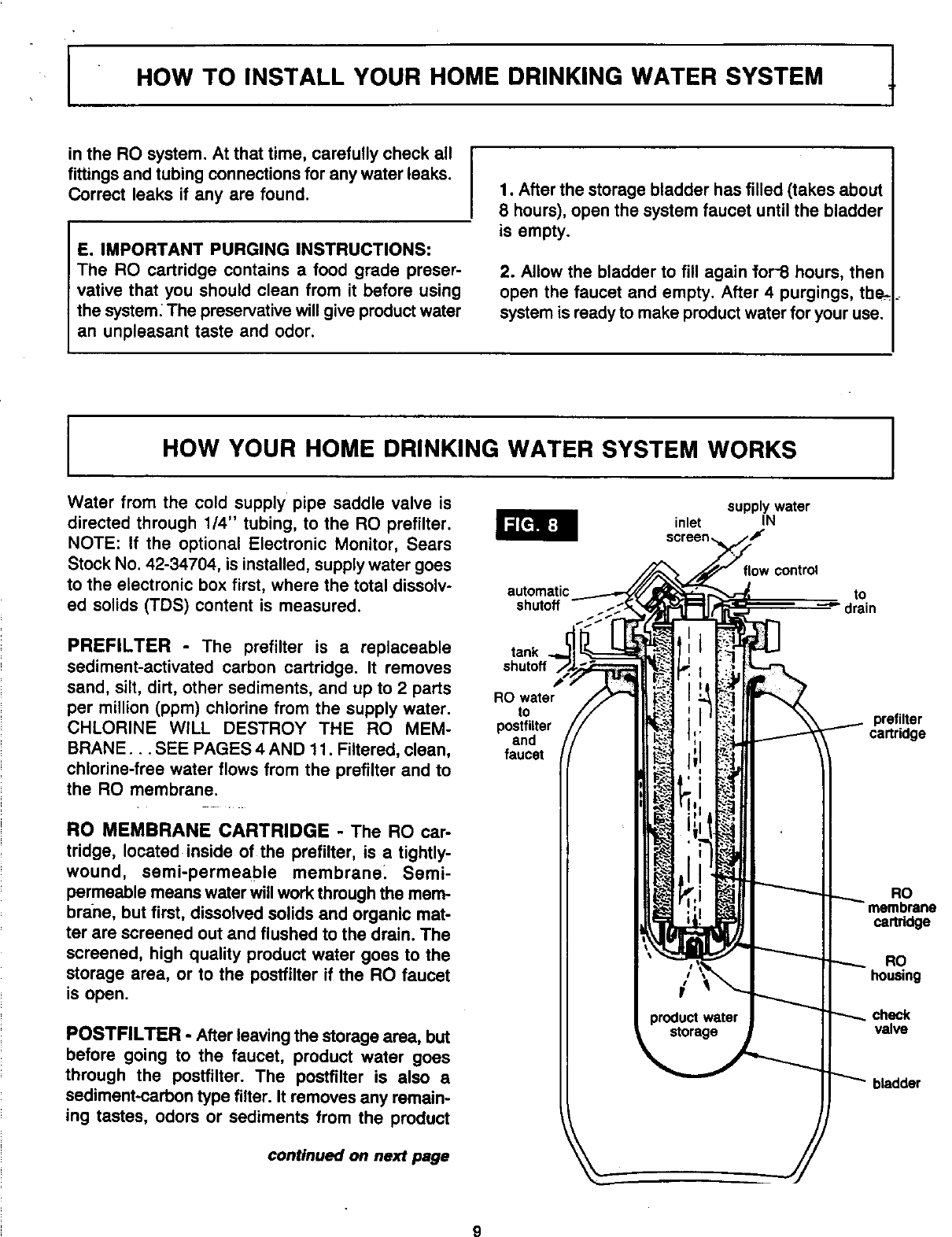
CHECK VALVE -A check valve (FIG. 8) is built
into the product water outlet of the RO housing. The
check valve prevents a backward flow of product
water, from the storage area, to the membrane. A
backward flow could rupture the RO membrane.
FLOW CONTROL -The flow control (FIG. 9)
keeps flow through the RO cartridge at the need-
ed rate for high quality product water. A cone
shaped screen fits over the flow control to help pre-
vent plugging with drain water sediments.
CARE OF YOUR HOME DRINKING WATER SYSTEM
To keep your Home Drinking Water System work-
ing and making high quality water, you must make
sure supplywate[ isalways within the limits shown
on page 15. This gives you the longest life from the
PREFiLTER CARTRIDGE, RO MEMBRANE CAR-
TRIDGE, and POSTFILTER. Each ofthese will wear
out in time and need replacing.
CAUTION: BEFORE WORKING ON THE
SYSTEM, DO THE FOLLOWING TO RELIEVE
WATER PRESSURE IN THE RO TANK.
la.Turn off the water supply to the RO (turn the
supply saddle valve handle all the way in-
ward... FIG. 7).
b. Close the tank shutoff valve (FIG 5 or 8).
c. Open the product water faucet and keep open.
d. Disconnect the posffilter.
e. Using a 2 gallon (minimum) container to catch
1
the water, open the tank shutoff valve to empty
the storage bladder ......
Looking at FIG. 9, or page 16, remove the pro-
tective cap and depress the relief valve stem,
allowing air to ENTER the tank (do not block
valve passage). Release the valve stem AFTER
flow from the shutoff valve slows to a slight drip.
Replace the protective cap.
CAUTION: This valve is for vacuum relief only. DO
NOT attempt to pressurize the tank.
3. Reconnect the postfilter.
INLET SCREEN -The inlet screen (FIG. 8 or 9) traps
sediments in the water supply before they can enter
the RO system. Check and clean or replace this
small screen (see parts section) often to assure
good water flow to the RO system.
10