Sears CRAFTSMAN 390.252157 User manual

OWNER’S
MANUAL
MODEL NO.
390.252157
CAUTION:
Read and Follow
All Safety Rules and
Operating Instructions
Before First Use of
This Product.
Save This Manual For
Future Reference.
Sears, Roebuck and Co., Hoffman Estates, IL 60179 U.S.A.
• Safety Instructions
• Installation
• Electrical
• Maintenance
• Repair Parts
PRINTED IN U.S.A.
PROFESSIONAL
1/2 HP SHALLOW WELL
WATER SYSTEM
®
Form No. F642-9805 (Rev. 6/5/98)

2
CONTENTS
INTRODUCTION/WARRANTY..........................................2
PUMP PERFORMANCE.......................................................3
MAJOR COMPONENTS ......................................................3
INSTALLATION................................................................4-5
ELECTRICAL.....................................................................5-6
OPERATION........................................................................7
MAINTENANCE ...............................................................7-9
HELPFUL HINTS ...............................................................10
TROUBLESHOOTING GUIDE...........................................11
REPAIR PARTS .............................................................12-14
INTRODUCTION
Please read our instructions before installing and using your
Shallow Well Water System. This will help you obtain the
full benefits of the quality and convenience built into this
equipment. It will also help you avoid any needless service
expenseresultingfrom causesbeyondour controlwhichare
not covered by our warranty.
Carefully read and follow all safety instructions in this
manual or on pump.
This is the safety alert symbol. When you see this
symbol on your pump or in this manual, look for one
of the following signal words and be alert to the potential
for personal injury!
warns about hazards that will cause serious
personal injury, death or major property damage if ignored.
warnsabouthazards thatwill or can causese-
rious personal injury, death or major property damage if ig-
nored.
warns about hazards that will or can cause
minor personal injury or property damage if ignored.
The word NOTICE indicates special instructions which are
important but not related to hazards.
Never run pump dry. Running pump without
water may cause pump to overheat, damaging seal and pos-
sibly causing burns to persons handling pump. Fill pump
with water before starting.
Never run pump against closed discharge.
To do so can boil water inside pump, causing hazardous
pressure in unit, risk of explosion and possibly scalding
persons handling pump.
Motor normally operates at high temperature
and will be too hot to touch. It is protected from heat dam-
ageduring operation by an automatic internal cutoff switch.
Before handling pump or motor, stop motor and allow to
cool for 20 minutes.
1. To avoid risk of serious bodily injury and property dam-
age, read safety instructions carefully before installing
pump.
2. Follow local and/or national plumbing and electrical
codes when installing pump.
3. Keep well covered while installing pump to prevent
leaves and other debris from falling into well, con-
taminating well and possibly damaging pump.
4. Protectpumpandpipingsystemfromfreezing.Allowing
pump or water system to freeze could severely damage
pump and voids warranty.
To avoid serious injury and equip-
ment damage, limit system pressure to 100 pounds
per square inch (PSI) or below at all times. Over-
pressure can cause tank blowup; install relief valve
capable of passing full pump volume at 100 PSI.
5. With a new well, test well for purity before use. Consult
local Health Department for procedure.
Hazardous voltage. Can shock, burn,
cause death, or start fires.
FULL ONE YEAR WARRANTY ON CRAFTSMAN®WELL PUMP
For one year from the date of purchase, Sears will repair or replace well pump, free of charge, if defective in material or workmanship.
LIMITED WARRANTY ON CRAFTSMAN®PROFESSIONAL HYDRO-GLASS®WELL PUMP
After one year and through three years from the date of purchase, Sears will furnish, free of charge, a replacement part for any defective part. You pay labor.
FULL FIVE YEAR WARRANTY ON CRAFTSMAN®CAPTIVE AIR TANK
For five years from date of purchase, Sears will repair or replace the tank, free of charge, if defective in material or workmanship.
This warranty does not cover repairs or replacement parts necessary because of abuse or negligence, including failure to install, adjust and operate this pump
according to the instructions in the owners manual. LIMITATION OF LIABILITY
SEARS WILL NOT BE LIABLE FOR LOSS OR DAMAGE TO PROPERTY OR ANY INCIDENTAL OR CONSEQUENTIAL LOSS OR EXPENSE FROM PROPERTY
DAMAGE DUE DIRECTLY OR INDIRECTLY FROM THE USE OF THIS PRODUCT.
Some states do not allow the exclusion or limitation of incidental or consequential damages, so the above limitation or exclusion may not apply to you.
WARRANTY SERVICE IS AVAILABLE BY SIMPLY CONTACTING THE NEAREST SEARS SERVICE CENTER/DEPARTMENT IN THE UNITED STATES.
This warranty applies only while this product is in the United States.
This warranty gives you specific legal rights, and you may also have other rights which vary from state to state.
Sears, Roebuck and Co., Dept. 817WA, Hoffman Estates, IL 60179
READ AND FOLLOW SAFETY INSTRUCTIONS!

3
SAFETY INSTRUCTIONS (Continued)
Pump Discharge Pumping Depth in Feet
Model Description Suct. Disch. Pressure PSI 5’ 10’ 15’ 20’
390.252157 1/2 HP S.W. Jet 1-1/4” 1” 40 8.2 7.3 6.2 5.0
TABLE I – Pump Performance (In Gallons per Minute)
NOTE: This system is designed for pumping depths of 20 feet or less.
6. Disconnect electrical power source before installing or
working on pump.
7. Ground pump with a ground wire run from grounding
lug on motor to a grounded lead in the service panel.
8. Line voltage and frequency of electrical power supply
must agree with motor nameplate.
9. Use of fuses or wire smaller than size recommended in
owner’s manual can cause overheating, possible fires,
and will void warranty.
Impeller and Jet
Impeller turns with motor shaft, causing water to fly out
from its rim by centrifugal force. Impeller rotation creates a
vacuum which pulls in more water. Part of the water is di-
vertedbackto thejetwhere itpassesthrough thenozzleand
venturi. This creates more vacuum to draw in more water.
In shallow wells (less than 20 feet deep), the vacuum cre-
ated at the pump is enough to pull water to the pump.
Therefore,forshallow wellusethe jetisbuilt intothepump.
Pre-Charged Tank
The tank serves two functions. It provides a reservoir of
water under pressure and maintains a cushion of air pres-
sure to prevent pipe hammering and possible damage to
plumbing components. When water is drawn off through
the house fixtures, the pressure in the tank is lowered and
the pump starts.
Pressure Switch
The pressure switch provides for automatic operation.
Pump starts when pressure drops to 40 pounds and stops
when pressure reaches 60 pounds.
Check Valve or Foot Valve
This pump is equipped with a built-in check valve. Install a
check valve as close to well as possible on well point in-
stallations.A foot valve must be installedin the well ondug
or cased wells. See Figures 2A and 2B, Page 4. For long hor-
izontal pipe runs, install check valve as close to well as pos-
sible (all types of wells).
BASIC TOOLS AND MATERIALS NEEDED
Plastic Pipe Installation
Tools Materials
Pipe Wrenches Plastic Pipe and Fittings (as required to complete job).
Screwdriver
Knife or Saw to Cut Plastic Pipe Teflon Tape (DO NOT use joint compound on plastic fittings).
Tire Pressure Gauge
Galvanized Steel Pipe Installation
Tools Materials
Pipe Wrenches Galvanized Pipe and Fittings (as required to complete job).
Screwdriver
Pipe Cutting and Threading Tools Pipe Joint Compound or Teflon Tape
Tire Pressure Gauge
MAJOR COMPONENTS AND WHAT THEY DO

INSTALLATION
4
INSTALLATION
Piping in the Well
The Shallow Well Water System can be installed on a dug
well, drilled well or with a driven point. In a dug or cased
well, a foot valve and strainer should be installed for easy
priming.It should beinstalled fivetoten feetbelow thelow-
est level to which the water will drop while the pump is op-
erating (pumping water level). To keep sediment from
clogging the strainer, be sure it is five to ten feet above the
bottom of the well. Before installing the foot valve, make
sure that it works freely.
When using a foot valve, a priming tee and plug as shown in
Figure 1, are recommended.
When installed on a driven point well, your Shallow Well
Water System should have a check valve installed as shown
in Figure 2A.
For a pump at sea level mounted directly over the well, be
sure the total lift from the pumping water level to the pump
does not exceed 20 feet. This will be less if the pump is off-
set from the well.
Themaximumlift ofanypump decreasesatthe rateofabout
1’ less lift for every 1,000 feet of elevation above sea level.
For example, at Denver, Colorado (Elev. 5,000’) the pump
loses five feet of lift. The maximum depth from which it
would pump water would therefore be 15 feet.
PUMP/TANK INSTALLATION
Pump
NOTICE: UseTeflon tapesupplied with thepump or Plasto-
Joint Stik1for making all pipe-thread connections to the
pump itself. To avoid stress-cracking, do not use pipe joint
compounds on the pump.
1. Wrap male pipe threads being attached to pump with
one or two layers of Teflon tape. Cover entire threaded
portion of pipe.
2. Donotovertightenthreadedfittingsintheplasticpump.
Be sure you do not try to tighten joint past thread stop
in pump port!
3. Ifleaks occur, remove fittings, clean offold tape, rewrap
with two to three layers of tape and remake the con-
nection. If joint still leaks, replace the fittings (fittings
may be undersized).
4. Be sure to support all piping connected to the System.
1Lake Chemical Co., Chicago, Illinois
Horizontal Piping from Well to Pump
When the pump is offset more than 25 feet from the well,
horizontal suction pipe size should be increased to reduce
friction losses. Never install a suction pipe that is smaller
than the suction tapping of the pump.
Check valve
Steel drive pipe
Drive coupling
Well point
Driven point
2894 0697
Priming Plug,
Priming Tee
(User Supplied)
To Service
From
Well
Plastic Pipe
Plastic Pipe
Foot Valve
and Strainer
Coupling
Well Seal
Dug or Cased Well
611 1293
Figure 1
Figure 2A
Figure 2B
Check Valve
Steel Drive Pipe
Drive coupling
Driven point
Well point

INSTALLATION
5
1-1/4” 1-1/2” 2”
Up to 25 Ft. 25 to 50 Ft. 50 to 200 Ft.
Discharge Pipe Sizes
When the pump is some distance from the house or point
of water use, the discharge pipe size should be increased to
reduce pressure losses caused by friction.
1” 1-1/4” 1-1/2”
Up to 25 Ft. 25 to 100 Ft. 100 to 600 Ft.
Tank
Tanksarepre-charged with40PSI airpressureat thefactory.
Your tank requires an air charge of 40 pounds per square
inch (PSI) for proper operation; check tank pressure with
tire gauge to determine if air charge needs adjustment. Tank
pre-charge should be checked annually; see instructions at
right.
In areas where the temperature is high for long periods of
time, the tank pre-charge pressure may increase. This may
reduce the tank drawdown (amount of water available per
cycle). If this occurs, reduce the pre-charge pressure to two
PSI below the pump cut-in setting of the pressure switch
(normally to 38 PSI).
It is necessary to flush all air out of the piping system and
water reservoir portion of the pre-charged tank. This is re-
quired on new installations, pumps requiring repriming and
pumps that have been disassembled for service. Do this as
follows:
1. Open faucets furthest from tank and allow pump to op-
erate.
2. Air in the system will cause a sputtering flow; allow
faucets to run until you have a steady, air free stream.
3. Open and close faucets repeatedly until you are sure all
air has been removed.
4. Ifstreamdoesnotbecomesteady,airmay be leakinginto
the system; check for leaks in the piping on the suction
side of the pump.
NOTICE: To prevent waterlogging, check tank air charge
annually.
To Check Tank Air Charge
If drawdown (amount of water available per cycle) de-
creases significantly, check as follows:
1. To check air charge in tank, shut off electric power to
pump, open faucet near tank, and drain completely.
2. At the air valve in top of tank, check air pressure with
standard tire gauge. Air pressure should be same as
pump pressure switch cut-in setting (40 PSI).
3. If the air pressure is below the cut-in setting, add air to
the tank. Use an air compressor or a portable air storage
tank.
4. Usesoaporliquiddetergenttocheckfor air leaksaround
air valve. Continuous bubbling indicates a leak. If neces-
sary, install new core in air valve. This is the same as
those used for automobile tubeless tires.
H20
H20H20
612 1293
1234 5
1. Tank nearly empty – air expands filling area above
vinyl separator.
2. Water begins to enter tank – air is compressed above
separator as it fills with water.
3. Pump-up cycle completed – air now compressed to
cut off setting of pressure switch.
4. Water being drawn from tank – compressed tank air
forces water out of separator.
5. Separator completely empty – new cycle ready to
begin.
Figure 3
Water Water Water
Table II Wiring Chart – Recommended Wire and Fuse Sizes
Distance in Feet from Motor to Meter
Branch 0’ to 101’ to 201’ to 301’ to 401’ to
Motor Max. Load Fuse* 100’ 200’ 300’ 400’ 500’
Horsepower Volts Amps. Rating Amps Wire Size
1/2 115/230 8.8/4.4 15/15 14/14 12/14 10/14 8/14 8/12
ELECTRICAL

Hazardous voltage. Can shock, burn, or
kill. Connect ground wire before connecting power
supply wires. Use the wire size (including the ground
wire) specified in the wiring chart. If possible, connect
the pump to a separate branch circuit with no other appli-
ances on it.
Explosion hazard. Do not ground to a gas
supply line.
WIRING CONNECTIONS
Fire hazard. Incorrect voltage can cause a
fire or seriously damage the motor and voids the warranty.
Thesupplyvoltage mustbewithin ±10%ofthe motorname-
plate voltage.
NOTICE: Dual-voltage motors are factory wired for 230
volts. If necessary, reconnect the motor for 115 volts, as
shown. Do not alter the wiring in single voltage motors.
Install, ground, wire, and maintain your pump in compli-
ance with the National Electrical Code (NEC) or the
Canadian Electrical Code (CEC), as applicable, and with all
local codes and ordinances that apply. Consult your local
building inspector for code information.
Connection Procedure:
1. Connect the ground wire first as shown in Figure 4. The
ground wire must be a solid copper wire at least as large
as the power supply wires.
2. There must be a solid metal connection between the
pressureswitch andthe motorfor motor grounding pro-
tection. If the pressure switch is not connected to the
motor, connect the green ground screw in the switch to
thegreen groundscrew underthe motor end cover. Use
a solid copper wire at least as large as the power supply
wires.
3. Connect the ground wire to a grounded lead in a service
panel, to a metal underground water pipe, to a metal
well casing at least ten feet (3M) long, or to a ground
electrode provided by the power company or the hydro
authority.
4. Connect the power supply wires to the pressure switch
as shown in Figure 4.
ELECTRICAL
6
Figure 4: Motor wiring connections through Pressure Switch. Match motor voltage to line voltage.
Your Motor Terminal Board (under the motor end cover)
and Pressure Switch look like one of those shown below.
Convertto 115Volts asshown. Donot changemotor wiring
if line voltage is 230 Volts or if you have a single voltage
motor. Connect power supply as shown for your type of
switch and your supply voltage.
A
B
L2
L1
A
B
L2
L1
A
B
L2
L1
A
B
L2
L1
230 Volt to 115 Volt Conversion, Spade Connector Type:
Move black wire
from A to L1.
1.
1.
2.
2.
3.
3.
230 Volt to 115 Volt Conversion, Plug-in Type:
Pull plug
straight
out from
terminal
board.
1.
1.
2.
2.
Plug in again
with arrow
on plug
pointing to
'115 Volts'.
3187 0398
A
L1
230
Volts
115
Volts
A
L1
230
Volts
115
Volts
A
B
L2
L1
A
B
L2
L1
Ground
Screw
Ground
Screw
Move white wire
with black tracer
from B to A.
Change Complete:
Clamp the power cable to prevent strain
on the terminal screws.
Connect the green (or bare copper) ground wire
to the green ground screw.
Motor wires connect here.
Clamp the power cable to prevent strain
on the terminal screws.
Connect the green (or bare copper) ground wire
to the green ground screw.
Motor wires connect here.
3187 0398
Power supply wires connect here.
230 Volt: Connect 2 hot wires (black and red)
here and cap the white (neutral) wire. It does
not matter which wire goes to which screw.
115 Volt: Connect one hot wire (black or red)
to one of these screws (it doesn't matter
which one). Connect the white (neutral) wire
to the other screw. Cap any remaining
black or red wires.
Disconnect power before working on pump, motor, pressure switch, or wiring.

OPERATION
Priming the Pump
NOTICE: To properly prime the pump, install a pipe tee in
the discharge piping (see Figure 1, Page 4).
Toprevent damageto internalparts, donot startmotor until
pump has been filled with water.
To prime pump:
1. Remove priming plug (Purchase separately; Figure 1,
Page 4).
2. Fill pump with water.
3. Replace priming plug, using Teflon tape or Plasto-Joint
Stik2on plug threads; tighten plug.
4. Startthepump.Watershouldbepumpedin 1-2 minutes.
If not, repeat steps 1, 2 and 3.
On shallow depths to water (10 feet or less), the pump
will probably prime the first time after the following
steps 1 through 4 above.
From 10 to 20 foot depths, you might have to shut off
the pump and repeat steps 1, 2 and 3 several times.
5. If, after priming pump several times, no water is
pumped, check the following:
A. Be sure suction pipe is in the water.
B. Be sure suction pipe does not leak.
C. Be sure that pump is not trying to lift water too high
(see “Piping in the Well”, Page 4).
D. As long as foot valve and check valve function cor-
rectlyand suctionpipe doesnot developleaks, pump
should not need repriming in normal service.
2Lake Chemical Co., Chicago, Illinois
MAINTENANCE
Lubrication
It is not necessary to lubricate the pump or its motor. The
motor bearings are lubricated for life. The mechanical shaft
seal in the pump is water lubricated and self-adjusting.
Draining for Winter
Risk of electric shock. Disconnect power
before working on unit.
Pump should be drained whenever it is disconnected from
service or is in danger of freezing.
1. DISCONNECT POWER.
2. Open faucet and relieve all pressure on system before
proceeding.
3. Disconnect pressure switch tube (Key No. 17, Page 12)
at barbed elbow on pressure switch (Key No. 28) and
allow tube to drain.
4. Open draincock (Key No. 22, Page 12) on pump body
and allow pump to drain.
5. Remove priming plug to vent pump; disconnect hose
(Key No. 6, Page 14) at tank end and drain pressure tank
and all piping to a point below the frost line.
6. Be sure to drain any piping that may be cut off from nor-
mal system drain due to check valve installation.
Vinyl Bag Removal
Be sure ALL air pressure has been re-
leased from tank before removing nuts from flange.
Failure to do this may result in serious or fatal injury.
Do not attempt to open tank unless all pressure has
been relieved!
Risk of electric shock. Disconnect power
before working on unit.
1. DISCONNECT POWER TO PUMP.
2. Drain system as follows:
A. Open faucet closest to tank.
B. Open draincock (Key No. 22, Page 12) on pump
body.
C. Remove hose (Key No. 6, Page 14) from tank elbow.
3. Relieve (expel) ALL air pressure in system by removing
valve core.
4. Disconnect outside piping from tank and pump.
To avoid serious or fatal injury, be
sure all air pressure has been released from tank
before proceeding to step 5.
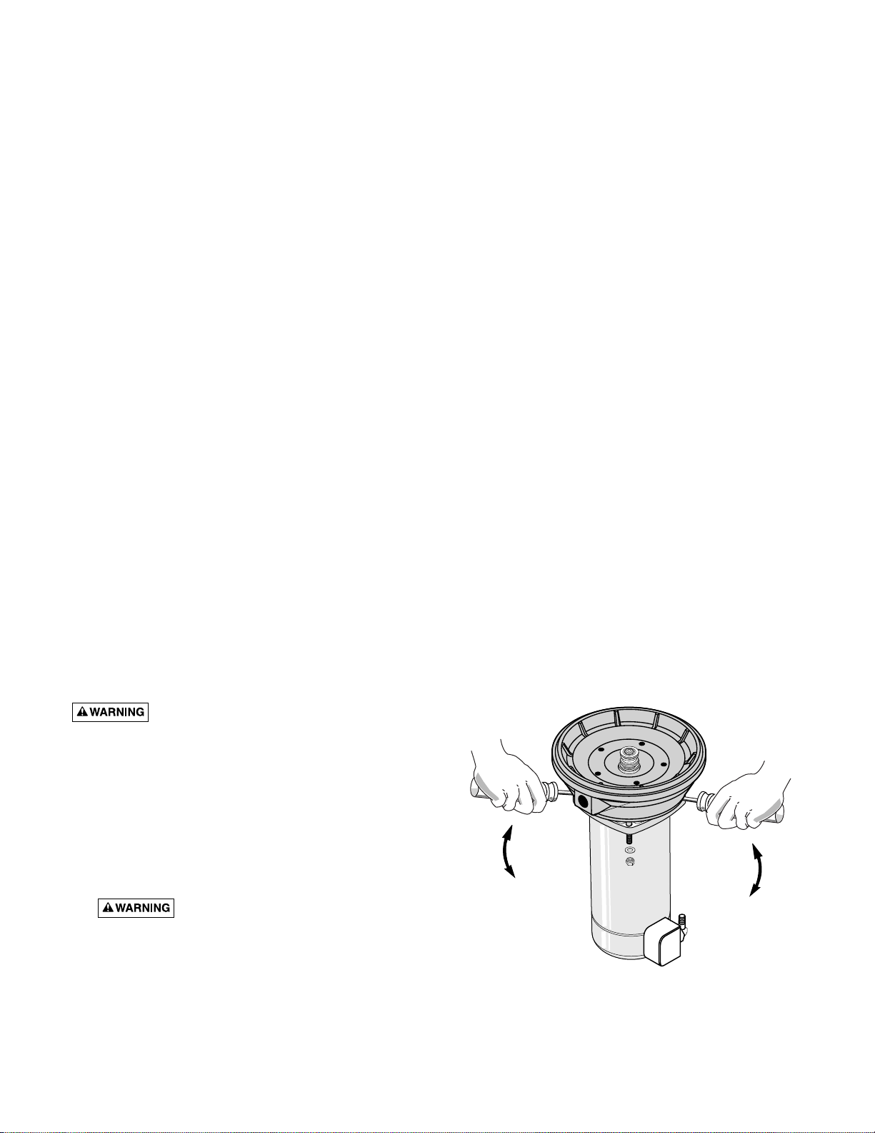
5. Remove nuts and washers from tank inlet flange (Key
No. 2, Page 14). Tap inlet flange to break seal. Remove
flange.
6. Wherever convenient, hold bag with pliers and cut with
single-edgerazor bladeor sharpknife. Bagwill notcome
out in one piece. Continue pulling and cutting until bag
is removed.
7. Clean and dry inside of tank.
8. Place replacement bag on a clean surface with opening
up. Flatten bag and force air out.
9. Tightly roll bag towards center opening.
10. Before center opening is covered up, force air out of re-
maining portion of bag. Finish rolling bag.
11. To make bag easier to insert into tank, sprinkle outside
of bag with talcum powder.
12. Beingcareful notto breakvalve, stand tank on end. Push
tightly rolled bag into tank.
13. Reach into bag and push out sidewalls. You need not
remove all wrinkles.
14. Clean center opening ring on bag and lip on tank.
15. Pull ring on bag through tank opening and fit over tank
lip. BE SURE it seats properly in groove on tank lip.
16. Clean sealing surface of inlet flange and place on studs.
17. NOTICE: Tighten nuts as follows:
A. Hand tighten all nuts.
B. Tighten one nut snug.
C. Tighten opposite nut snug.
D. Proceed, tightening opposite pairs to a snug fit.
E. Recheck all nuts, using same pattern. Be sure all nuts
are tight and you have a good seal.
7

MAINTENANCE
NOTICE: Do not overtighten; you may twist studs off of
tank. If you have a torque wrench, tighten to 85 inch-
pounds torque.
18. Stand tank on feet and reconnect piping.
19. Recharge tank to proper air pressure (see Page 5).
20. Reconnecthosesandpressureswitchtube;primepump
(see Page 6).
Air Valve Replacement
1. Follow steps 1 through 5 under “Vinyl Bag Removal”,
Page 7.
2. Cutvalve off as close to tank as possible. Push remaining
portion back into tank.
3. Tip tank on end and BE SURE all water is drained from
bag.
4. Carefully remove bag ring from lip on tank opening and
push bag ring back into tank; reach in around it and re-
move cut off portion of valve from tank.
5. Wipe a thin film of soapy solution on replacement valve
and from inside tank insert in hole in top of tank.
6. Pull valve through hole with pliers or a valve tool (avail-
able at your local filling station or Automotive Center).
7. Follow steps 14 through 20 under “Vinyl Bag Removal”,
Page 7, to reinstall bag in tank.
Testing for Bag Leakage
1. Follow steps 1 through 4 under “Vinyl Bag Removal”,
Page 7.
2. Tip tank on end, valve down. Be careful not to break
valve!
3. Ifbag leaks,water will run out of valve. If so, replacebag
as instructed above.
DISASSEMBLY AND
ASSEMBLY OF PUMP
Risk of electric shock. Ground unit and
disconnect power before attempting any work on
pump or motor.
Your Sears pump is designed for ease in servicing. Should
repair or replacement of the motor or seal be needed, the
pump and piping do not need to be disconnected or dis-
turbed.
1. Disassemble pump as follows:
A. Disconnect power.
B. Drainpumpbyopeningdraincock.Removepressure
switch tubing from fitting on top of pump.
To avoid serious injury, release all
pressure from system before attempting to remove
clamp from pump.
C. Remove clamp, Key No. 10, Page 12.
D. Remove pump base mounting bolts. Motor assembly
and back half assembly of pump can be pulled away
from front half.
E. Remove “O” rings.
2. Reassembly of pump.
A. Clean “O” rings and “O” ring grooves.
B. Lubricate“O” rings with petroleumjelly, and place in
grooves.
C. Slide pump halves together.
D. Clean inside of clamp. Place clamp around pump
halves.Alternatelytightenclampscrewandtapclamp
around outside with plastic mallet. This will insure
proper seating of “O” ring and clamp.
E. Assemble base mounting bolts. Connect pressure
switch tubing and close drain cock.
F. Prime pump and turn on power.
G. Check for leaks.
Removing Motor for Service
and Replacing Shaft Seal
If it is necessary to separate motor and seal plate, always re-
place the shaft seal. We suggest you purchase this item,
U109-6A, and have it on hand for future use.
NOTICE: The seal consists of two parts, a rotating member
and a ceramic seat. The surfaces of the seal are easily dam-
aged. Read instructions carefully.
1. Disassemble pump per instructions above.
2. Removediffuser andimpeller asfollows (Key Nos. 8 and
9, Page 12).
A. Remove screws holding diffuser.
B. Loosen two screws and remove motor canopy from
motor.
C. Place 7/16” open end wrench on motor shaft flat.
D. Turn impeller counterclockwise when facing it.
3. Removepumpbackhalffrommotorbyunscrewing four
(4) nuts. Pry back half off motor by inserting two (2)
screwdriversbetweenthebackpumphalfandthe motor
flange. This will force rotating portion of seal off shaft.
See Figure 5.
8
475 0194
Figure 5

MAINTENANCE
9
4. Place back half of pump on flat surface and tap out ce-
ramic seat. See Figure 6.
5. Clean seal cavity.
6. Install new seal.
A. Clean polished surface of ceramic seat with clean
cloth.
B. Wet outer edge of “O” Ring with detergent solution.
C. With finger pressure press seat firmly and squarely
into cavity. See Figure 7A. Polished face of seat faces
inside of pump. If seat will not locate properly, place
cardboardwasheroverpolishedfaceandusepiece of
3/4” standard pipe for pressing purposes. See Figure
7B.
D. Dispose of cardboard washer and clean surface of
seat.
E. Clean motor shaft.
F. Reassemble back half of pump to motor.
G. Apply detergent solution to inside diameter of rotat-
ing seal member.
H. Sliderotating memberon shaft untilrubber drivering
hitsshaftshoulder.NOTICE:BE SUREyoudonot chip
orscratch seal face on shaft shoulder or seal willleak!
I. Screw impeller on shaft (clockwise) while holding
shaft with 7/16” open end wrench on shaft flats. This
will automatically locate seal in place. See Figure 8.
J. Remount diffuser on seal plate.
Cleaning Impeller
1. Follow steps 1A through 1E under “Disassembly and
Assembly of Pump” on Page 8.
2. Remove diffuser and impeller from pump per instruc-
tions under “Removing Motor for Service and Replacing
Shaft Seal” on Page 8.
3. Clean impeller and reassemble impeller and diffuser per
instructions under “Removing Motor for Service and
Replacing Shaft Seal” on Pages 8 and 9.
Cleaning Shallow Well Jet
To remove debris from venturi or nozzle, proceed as fol-
lows:
1. Disassemble pump per instructions on Page 8.
2. Turn venturi counterclockwise and remove it. The noz-
zle is now exposed. Remove it using a 5/8” hex socket
wrench with extension. Turn counterclockwise. If
socket wrench is not available, insert an ice pick or sim-
ilar pointed tool carefully into the nozzle. This will dis-
lodge debris.
3. Flush out the debris by running water through the noz-
zle in the same direction as the dislodging tool was in-
serted.
4. Reinstall nozzle and venturi. Do not overtighten!
5. Reassemble pump per instructions on Pages 8 and 9.
479 0194
477 0194
478 0194
Figure 6
Figure 7A Figure 7B
Figure 8
483 0194

HELPFUL HINTS
10
How to Handle a Gaseous Well
In some areas well water contains gases which must be al-
lowed to escape before the water is used. This can be done
as shown in Figure 9.
Agood wayof delivering gas-freewater isto suspend a pipe,
closed at the bottom and open at the top, surrounding the
suction pipe. Since the gases rise in the well casing, the
water sucked down through the pipe and into the suction
pipe is free of gas. This type of well must be vented to the
outside of any enclosure.
Not
to
Scale
Pipe strap or
wire to hold
pipe sleeve
Pipe
sleeve
Pipe
cap
Tail
pipe
Foot
valve
2369 0396
Gases
rise to
surface
Figure 9

TROUBLESHOOTING GUIDE
11
TROUBLE POSSIBLE CAUSES REMEDIES
Motor will not run 1. Disconnect switch is off 1. Be sure switch is on
2. Fuse is blown 2. Replace fuse
3. Starting switch is defective 3. Replace starting switch
4. Wires at motor are loose, 4. Refer to instructions on wiring
disconnected, or wired incorrectly
*5. Motor is wired incorrectly 5. Refer to instructions on wiring
6. Pressure switch contacts are dirty 6. Clean by sliding piece of plain paper between contacts
Motor runs hot and *1. Motor is wired incorrectly 1. Refer to instructions on wiring
overload kicks off 2. Voltage is too low 2. Check with power company. Install heavier wiring
if wire size is too small. See wiring instructions
3. Pump cycles too frequently 3. See section below on too frequent cycling
Motor runs but no *1. Pump in a new installation did 1. In new installation:
water is delivered not pick up prime through:
a. Improper priming a. Re-prime according to instructions
b. Air leaks b. Check all connections on suction line and jet
c. Leaking foot valve c. Replace foot valve
*2. Pump has lost its prime through: 2. In installation already in use:
a. Air leaks a. Check all connections on suction line, jet and shaft seal
b. Water level below suction of pump b. Lower suction line into water and re-prime. If receding
water level in a shallow well operation exceeds
suction lift, a deep well pump is needed
3. Jet or impeller is plugged 3. Clean jet or impeller according to instructions
4. Check valve or foot valve is stuck 4. Replace check valve or foot valve
in closed position
5. Pipes are frozen 5. Thaw pipes. Bury pipes below frost line. Heat pit or
pump house
6. Foot valve and/or strainer are 6. Raise foot valve and/or strainer above well bottom
buried in sand or mud
Pump does not 1. Water level in well is lower than 1. A deep well jet pump may be needed (over 20 ft. to water)
deliver water to full estimated
capacity (also check 2. Steel piping (if used) is corroded or 2. Replace with Plastic Pipe where possible, otherwise with
point 3 immediately limed, causing excess friction new steel pipe
above) 3. Offset piping is too small in size 3. Use larger offset piping
Pump pumps water 1. Pressure switch is out of adjustment 1. Adjust or replace pressure switch
but does not shut off or contacts are “frozen”
2. Faucets have been left open 2. Close faucets
3. Jet or impeller is clogged 3. Clean jet or impeller
*4. Motor is wired incorrectly 4. Refer to instructions on wiring
5. Water level in well is lower than 5. Check possibility of using a deep well jet pump
estimated
Pump cycles too 1. Pipes leak 1. Check connections, replace pipe fittings
frequently 2. Faucets or valves are open 2. Close faucets or valves
3. Foot valve leaks 3. Replace foot valve
4. Pressure switch is out of adjustment 4. Adjust or replace pressure switch
5. Air charge too low in 5. Disconnect electrical power and open faucets until all
Captive Air® Tank pressure is relieved. Using automobile tire pressure
gauge, check air pressure in tank at the valve stem
located at top of tank. If less than 30 pounds, pump air
into tank from outside source, until 30 pounds pressure
is reached. Check air valve for leaks, using soapy
solution, and replace core if necessary
Air spurts from 1. Pump is picking up prime 1. As soon as pump picks up prime, all air will be ejected
faucets 2. Leak in suction side of pump 2. Check suction piping, make sure joints are not sucking air
3. Well is gaseous 3. Change installation as described in manual
4. Intermittent over-pumping of well 4. Lower foot valve if possible, otherwise restrict discharge
side of pump
Leaks at the metal 1. Loose clamps or “O” ring 1. First check the clamp tightening screw to see if it is tight.
clamp not sealed If it is tight and slight leakage still occurs, place a piece
of wood on the periphery of the clamp and firmly tap the
wood with a hammer. Repeat this operation around the
edge of the clamp and retighten the clamp screw. If leak
continues, disassemble clamp and pump halves and
check to see that “O” ring is properly seated and no
foreign material is on “O” ring or “O” seat.
Reassemble pump.
(*Note: Check
prime before look-
ing for other
causes. Unscrew
priming plug and
see if there is water
in priming hole)
Release all pressure
in system before
working on clamp!

REPAIR PARTS
12
1
23 4
5
6
7
8
910
11 12 13 14
15 16 17 18
19 20
21
22
23
25
26 26A
27
28
29 30
587 1193
24
Pump Only – Model 390.252157
To Order Parts in the U.S.A., Call
Sears Product Service, 1-800-366-7278
To Order Parts outside the U.S.A., Call
Your local Sears Service Center or Store
1A
L1
L2
1B 1C
1D
1E
Wiring omitted
for clarity

REPAIR PARTS
13
Key Model 390.252157 Part
No. 1/2 HP Description
1** J218-953C Motor - 1/2 HP - 115/230V - 60 Cycle
(Includes Key Nos. 1A through 1E)
1A U18-1103 Overload Protector
1B U18-1180 Terminal Board
1C U18-1098 Contactor
1D U18-128 Governor
1E U18-526 Capacitor
2 C69-2 Water Slinger
3* U78-107PT Reducer Bushing - 1/2” x 1/8” NPT
4 WC78-41T Pipe Plug - 1/8” NPT
5 L176-47P Tank Body (Back Half)
6 U9-399 “O” Ring - Tank Body - 9-1/2” x 9” x 1/4”
7 U109-6A Shaft Seal
8 J105-40PE Impeller
9 J1-39P Diffuser
10 C19-54SS Clamp - Tank Body
11 U9-201 “O” Ring - Venturi - 1-3/8” x 1-1/8” x 1/8”
12 N32P-66 Venturi
13 N34P-19 Nozzle
14 N76-29P Insert
15 J20-18 Gasket
16 N176-28PB Tank Body Assembly (Front Half - Includes
Key No’s. 11, 12, 13, 14, 15, 16, 19, 20, 21, 23 and 24)
16 N76-28P Tank Body Only - Front Half
17 U37-673P Switch Tube
18 U111-212T 90° Hose Barb
19 U9-226 “O” Ring - Check Valve - 2-1/4” x 2” x 1/8”
20 N166-5P Check Valve
21* WC78-41T Pipe Plug - 1/8” NPT (2 Required)
22 U212-68T Draincock - 1/4” NPT
23 U30-742SS Screw - #10 - 16 x 1-1/8” (4 Required)
24 U30-542SS Screw - #8 - 32 x 7/8” (5 Required)
25 C4-42P Base
26* U36-37ZP Nut - 5/16” - 18 Hex Head (4 Required)
26A U43-11ZP Lockwasher (4 Required)
27 C35-11 Motor Pad
28 2782 Pressure Switch
29 U36-112ZP Locknut - 1/2”
30 L43-5C Connector
* Standard hardware item, may be purchased locally.
** For repair or service to motors, always give the motor model number.

REPAIR PARTS
14
123
4
7
2952 0697
6 5
Tank Only – Model 390.252157
To Order Parts in the U.S.A., Call
Sears Product Service, 1-800-366-7278
To Order Parts outside the U.S.A., Call
Your local Sears Service Center or Store
Model 390.252157
Key 1/2 HP Qty.
No. Part Number Used Description
1 29135 1 Tank Assembly (Includes Diaphragm, Elbow,
Valve, Nuts, Washers, & Inlet Flange)
• U20-13 1 Bag - Vinyl
• U212-160 † 1 Air Valve w/Cap
2 U31-350P 1 Inlet Flange
3 U36-202BT † 6 Nut - 5/16-18 Hex
4 U78-769P † 1 Elbow 1” NPT x 1” Insert
5 U19-55SS 2 Clamp
6 U74-37V 1 Hose - 1” x 24-1/2”
7 U78-777P 1 Adapter - 1” Pipe to 1” NPT
REPAIR PARTS
• Not illustrated.
† Standard hardware item, may be purchased locally.

15

For the repair or replacement parts you need
Call 7 am - 7 pm, 7 days a week
1-800-366-PART
(1-800-366-7278)
For in-home major brand repair service
Call 24 hours a day, 7 days a week
1-800-4-REPAIR
(1-800-473-7247)
For the location of a
Sears Repair Service Center in your area
Call 24 hours a day, 7 days a week
1-800-488-1222
For information on purchasing a Sears
Maintenance Agreement or to inquire
about an existing Agreement
call 9 am - 5 pm, Monday-Saturday
1-800-827-6655
MAINTENANCE
AGREEMENT
America's Repair Specialists
REPAIR SERVICES
America's Repair Specialists
REPAIR SERVICES
America's Repair Specialists
REPAIR SERVICES
Sears, Roebuck and Co., Hoffman Estates, IL 60179 U.S.A.
OWNER’S
MANUAL
Model No.
390.252157
The model number of
your Shallow Well Water
System will be found on
the pump body.
When requesting service
or ordering parts, always
give the following
information:
• Product Type
• Model Number
• Part Number
• Part Description
PROFESSIONAL
1/2 HP SHALLOW WELL
WATER SYSTEM
®
Table of contents
Other Sears Water System manuals
Popular Water System manuals by other brands

Armstrong
Armstrong AGEplus Series Installation and operating instructions

WaterGeneral
WaterGeneral RD-322 Installation & service manual

Bunn
Bunn Easy Clear EDSS-11-T200F specification

Microline
Microline 335 Installation, operation & service manual

Burkert
Burkert 8821 operating instructions

Sota
Sota WOZ5 instructions

Sungrabber
Sungrabber Solar Hot Water System owner's manual

Everpure
Everpure Insurice Single PF-i20002 Specification sheet

Orkli
Orkli OKSOL-150 installation guide

Pelican
Pelican Premium WHWF 1865 owner's manual

Culligan
Culligan Aqua-Cleer Aqua-Cleer Advanced Drinking Water... owner's guide

A.O. Smith
A.O. Smith Dura-Max AJH - 1000A - P instruction manual