SEAS 4041 User manual

Sea Systems AB - Terminalgatan 19A - SE 235 39 Vellinge - Sweden
Tel.: +46 40420250 - www.seasystems.se
SEAS 4041_Inst Manual Rev. 1.0.pdf
INSTALLATION MANUAL
SEAS 4041
Line Amplier;56/64 outlets;36/44 dB
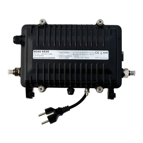
The SEAS 4041 power supply and amplier is designed to supply power to an active
antenna as well as amplifying radio and TV signals for distribution in networks. It comes
with a
Multistandard modulator built in for PAL, SECAM, NTSC.
The amplier is equipped
with automatic level control (ALC) that reduces gain in case of overload. The power supply
accepts 110 to 230VAC. The unit is designed for indoor use only.
The attenuation of each band can be separately controlled.
Like all other SEAS products, the SEAS 4041 series are designed to meet the special re-
quirements of world-wide marine use.
- 47~860 MHz amplier, forward gain is 40dB
- Plug-in modules design for easy installation.
- Plug-in ALC modules for wide range operation
- Wall mounting with brackets delivered with amplier
- 4x outputs (3/8”-32 UNEF F-Female connectors)
-
Multistandard modulator built in for PAL, SECAM, NTSC
- 1/7 -
FEATURES
SEAS 4041 for up to 64 outlets (36/44dB)
Size: (L) 262 x (W) 200 x (H) 130 mm
INSTALLATION
Never install the line amplier with out looking at the instructions inside! Make sure to
know which connections go where before connecting cables etc.

TECHNICAL SPECIFICATIONS
INSTALLATION MANUAL
SEAS 4041
Line Amplier;56/64 outlets;36/44 dB
MECHANICAL MEASUREMENTS
Metal Housing
BLOCK DIAGRAM
Sea Systems AB - Terminalgatan 19A - SE 235 39 Vellinge - Sweden
Tel.: +46 40420250 - www.seasystems.se
- 2/7 -
RA-30

INSTALLATION MANUAL
All specications stated are subject to change without notice.
SEAS 4041
Line Amplier;56/64 outlets;36/44 dB
Sea Systems AB - Terminalgatan 19A - SE 235 39 Vellinge - Sweden
Tel.: +46 40420250 - www.seasystems.se
- 3/7 -
TECHNICAL SPECIFICATION
Size (H) 262 x (W) 200 x (D) 130 mm
Housing Aluminium Die-casting, Finishing: Black painted
Connectors IN: 5/8”-24 NEF F-Female to 3/8”-32 UNEF F-Female Adaptor
OUT: F-Female Connector (4 pcs)
Weight 3.50 Kg
Electrical Specication
RF Amplication Push-Pull Hybrid Module
Operation Gain (w/ RA-30) 100 KHz 16.5 dB min.
5 MHz 22.0 dB min.
IN-OUT 27 MHz 27.0 dB min.
47~862 MHz 36.0 dB min. w. 4 outputs
47~862 MHz 42.0 dB min. w. 1 output
Operation Gain 44.0 dB min.
Gain Control 0~ -18.0 dB (adj.)
Slope Control (w/ MS-86/ 18) 0~ -18.0 dB (adj.)
Auto Level Control (w/ ALC-12) +/-12.0 dB
Noice Figure 47~862 MHz 8.0 dB typ. 9.0 dB max.
Output Level (Reference) 55/ 550/ 862 MHz 77 NTSC chs. +312 MHz digital*
(97 / 102 / 94 dBu V)
Composite Second Order (CSO) -60 dBc
Composite Triple Beat (CTB) -60 dBc
Cross Modulation (XMOD) -60 dBc
Return Loss 100~300 KHz 6 dB min.
(w/ Jumpers) 300 KHz~27 MHz 14 dB typ. 12 dB min.
47~862 MHz 12 dB typ. 10 dB min.
General Specications
Input & Output Test Ports -20 +/- 2 dB, F-Female
Input & Output Impedance 75 Ohm
Surge Protection 7000 V for 1.2 x 50 us
Power Supply 110-230 Vac, 50/60 Hz
Fuse (For Power Supply) 0.2 A / 250 V (230 Vac)
Power Consumption (Including Powering output to Antenna) 16 W, (25W)
AC Cord AC Inlet Module; 1,5m cord w. Schuko
Operating Temperature -40 to +60°C
EMC & Safety
EMC EN60945:2002, EN55027-2, EN61000-3-2/3-3/4-2-4-6
Safety EN60950, EN60601
Dieletric Strength Test** >2M Ohm, <1m A @2120VDC
Protective Earth Connection*** <0.1 Ohm
Modulator Specications
Video input
Frequency range 20 Hz - 6 MHz
Level/impedance 1 V +/- 0.1 V/75 Ohm
Audio input
Frequency range 20 Hz - 15 kHz
Level Adjustment 0 - 7dB
Level/impedance/deviation**** 2x775 mV RMS/10 kOHM/50 kHz
RF Output
Level adjustment 0 Hz - 20 dB
Output channels according channels charts B/G/D/K/H/I/L/M/N/Australia
Frequency range 45-84 MHz, 170-300 MHz, 470-862 MHz
Sound subcarrier frequency 4.5 MHz, 5.5 MHz, 6.0 MHz, 6.5 MHz
Fine tuning range of video carrier frequency +/- 2.25 MHz max. by 0.25 MHz step
Video frequency response +/1 dB
A/V ratio 12/16 dB
Amplitude modulation depth, typical 81%
Signal/noise ratio, weighted >/=55 dB
*) For digital channels at 550~862 MHz, carriers arc -10 dB lower ralative to analog channels.
**) Test by Hi-Pot tester.
** *) Test by Voltage Meter applied between the protective earth contact of the mains plug and all accessible conductive parts.
****) Available to set standard deviation +/- 50 kHz of sound carrier when input level 340mV-775mV in both audio inputs.
TV
system
Dis-
played
Audio
Subcarrier
Video
standard
B/G b5 5.5 MHz PAL
D/K d6 6.5 MHz PAL/SECAM
Australia A5 5.5 MHz PAL
I,6 6.0 MHz PAL
L L6 6.5 MHz SECAM
MJ4 4.5 MHz PAL/NTSC
N U4 4.5 MHz PAL/NTSC

SEAS 4041
Line Amplier;56/64 outlets;36/44 dB
INSTALLATION MANUAL
Sea Systems AB - Terminalgatan 19A - SE 235 39 Vellinge - Sweden
Tel.: +46 40420250 - www.seasystems.se
- 4/7 -
The SEAS 4041 equipment shall be installed by
approved/qualied installer, and only indoor
installation is approved. The power supply in SEAS
4041 is equipped with CE approved power cable as
standard. The unit shall be mounted in a well
ventilated enviroment.
The in and out are normally mounted with
F-connectors.The screen of the coaxial cable
distribution system shall be connected to earth in
the building installation.
The mains plug is used as the disconnect device and
shall remain readily operable at all time. The
integrity of the protective earth must be ensured.
Be sure to connect to an appropriate mains socket
outlet with protective grounding connection.
Improper grounding can result in an electrical shock.
F-connector stripping
CONNECTING SEAS 4041
Line IN -->
15 VAC OUT <--
Max 300mA
110-230 VAC IN -->
Line OUT -->
Line OUT -->
Line OUT -->
Line OUT -->
Line OUT -->

SEAS 4041
Line Amplier;56/64 outlets;36/44 dB
INSTALLATION MANUAL
Sea Systems AB - Terminalgatan 19A - SE 235 39 Vellinge - Sweden
Tel.: +46 40420250 - www.seasystems.se
- 5/7 -
TV MODULATOR MANUAL
The TV modulator is intended to form TV channels of B/G/D/K/I/L/M/N/
Australia standards in VHF and UHF ranges.
Broadcasting signal has double sideband modulation.
The modulators are intended for indoor use only. Suitable for moderate
and tropical climates. RoHS compliant.
PRODUCT DESCRIPTION
1: AUDIO L - audio left channel signal input connector (RCA type)
2: AUDIO R - audio right channel signal input connector (RCA type)
3: VIDEO - video signal input connector (RCA type)
4: RF OUT - RF signal output connector (F type)
5: RF IN - RF signal input connector (F type)
6: RF OUT - RF output signal level regulator
7: Two-digit LED display
8: AUDIO - sound subcarrier deviation regulator
1 2 3
4
5
6
7
8
Figure 1.
INSTALLATION INSTRUCTIONS
DEFAULT SETTINGS
1. Output channel E02;
2. Audio subcarrier deviation ±50 kHz (when audio signal level 1 kHz is 775 mV);
3. B/G standard; audio subcarrier 5.5 MHz (Preset b5);
4. Test pattern generator OFF (Preset no);
5. Frequency shift none (Preset 0);
6. P/S ratio -16 dB (Preset I6);
7. Output signal on (Preset on);
8. Sound subcarriers deviation regulator
The modulator has two modes of operating:
1. normal: sets after plug in; Output channel can be selected in normal mode by pressing buttons “-“ or “+” (see tables 2-11).
2. setting: to enter the setting mode press and hold “-“ and “+” buttons simultaneously for 1 second, to exit setting mode
press and hold “-“ and “+” buttons simultaneously for 1 second.
Select of necessary to change parameter by pressing button “-“ and set necessary mode by pressing “+” button.
OPERATING
CHANGING SETTINGS
1. TV system setting:
a) After switching settings mode, indicator displays current TV system (see table 1);
b) Set necessary TV system by pressing “-“ button (see tables 2-11);
c) After TV system changing, modulator sets to rst channel of selected TV system (see tables 2-11), other settings
remains unchanced.
2. Test pattern generator:
a) Press “-“ button;
b) Switching between OFF and ON by pressing button “+”, “no” - test pattern generator OFF, “t5” - test pattern generator
ON.
3. Fine tuning of video carrier frequency:
a) Press button “-“;
b) Shift video carrier frequency by pressing button “+” (see table 12).
4. Picture/sound ratio switching:
a) press button “-“;
b) switching between 12 dB and 16 dB by pressing button “+”.
5. Output signal switching:
a) Press button “-“;
b) Switching between RF ON and RF OFF by pressing button “+”, “on” - RF ON, “oF” - RF OFF.
6. Sound subcarriers deviation regulation (for MT57):
a) Press button “-“;
b) Set necessary deviation by pressing button “+“ (see table 13).

SEAS 4041
Line Amplier;56/64 outlets;36/44 dB
INSTALLATION MANUAL
TV MODULATOR MANUAL (CONTINUED)
Sea Systems AB - Terminalgatan 19A - SE 235 39 Vellinge - Sweden
Tel.: +46 40420250 - www.seasystems.se
- 6/7 -
To prevent unauthorized access press buttons “-” and “+” simultaneously twice in 0.5 sec. “LO” will briey be displayed. To
revert to normal operation, repeat above procedure. “UL” will briey be displayed. The symbol “LO” appears, if you try to
change settings in locked mode.
PROTECTION FROM UNAUTHORIZED ACCESS
When input signal level is from 340 mV to 775 mV in both audio inputs, use a regulator (gure 1, position 11) to set the
sound subcarrier deviation ±50 kHz. The factory set sound subcarrier deviation is ±50 kHz for an input signal level of 775 mV
in both audio inputs.
SOUND SUBCARRIER DEVIATION SETTING
Use a regulator (gure 1, position 6) to adjust an output level. Output level adjustment range is 0 ÷ -20 dB.
OUTPUT SIGNAL LEVEL ADJUSTMENT
Table 1.
Table 2.
Table 3.
Table 5.
Table 4. Table 6.
Table 7.
Table 8.

SEAS 4041
Line Amplier;56/64 outlets;36/44 dB
INSTALLATION MANUAL
TV MODULATOR MANUAL (CONTINUED)
Sea Systems AB - Terminalgatan 19A - SE 235 39 Vellinge - Sweden
Tel.: +46 40420250 - www.seasystems.se
- 7/7 -
FINE TUNING
Table 12.
Table 13.
Table 9. Table 10.
Table 11.
Table of contents
Other SEAS Amplifier manuals

