SeaSoft MobilGate - 128c User manual

MobilGate - 128c Gate and barrier control GSM module with
2 inputs and 2 outputs for 128 phone numbers
MobilGate-128c is an industrial GSM module developed for remotely controlling doors, garage
doors and barriers with 2 opto-isolated inputs and 4 high current relay outputs. The 2 relay outputs
allow the configuration of 128 phone numbers to control the gates remotely with a free call based on
caller ID recognition. The 2 relay outputs can be triggered by SMS orders received from previously
configured phone numbers. Relays operated with a free call can be triggered for pre-determined
duration, and the relays operated with SMSs can be turned on and off permanently. The recognition
of maximum 128 phone numbers allows to set up entitlements for 128 users. The general inputs can
be used arbitrarily for transmitting gate error signals, burglary alarm center's signals or panic signals.
Users are informed about input changes via
SMS with pre-configured content. Certain
electronic devices, such as heaters, air
conditioners, light devices etc. can be
turned on and off with relay outputs
operated via SMSs, thus the function of
gate opener can be broadened with many
supplements. Its power voltage is 10-30V,
which can be supplied by a power adapter.
Its setup can be configured with our free
downloader software via USB port, or by
sending several different configuration SMS
remotely. Each input and output can be
labeled with a max. 16-character long name.
The configuration of the SMS relay output commands which trigger the relays to be on or off also
can be set. The module also has a 4-character passcode in order to prevent any unauthorized
personnel to disable or reconfigure the module. The GSM gate opener has internal timers, thus the
output relays are triggered for a configured time when calls occur, which can be maximum of 9999
seconds (about 3 hours). After the given time expires, the relays turn off automatically and return to
their original state.
1. Operation of MobilGate-128c
The GSM gate opener is equipped with a carrier-independent industrial GSM module; thus it
is ready for SMS-based communication with a prepaid or subscription SIM card without PIN code.
The data which is necessary for operation, for instance SMS number of the service provider, users’
numbers, output and input names etc. can be configured by downloading them into the device or
sending an SMS with a certain content. In the case there is any change of the inputs, the module
name, module number, the appropriate input name and status are also sent via SMS. The detailed
messages provide possibility to be able to easily identify the appropriate device in case of having
more than one. Input and output status with every parameter can be queried by sending a
corresponding SMS. Configuration SMSs are confirmed after reception, and an incorrect
configuration SMS will result in an error message. The module does not discard the previously set
configuration, including input names, output status, phone numbers, etc. after turning the device off.
After power-up, although timer parameters are deleted, but the module continues its operation where
SeaSoft Ltd. www.seasoft.hu - www.mobil-control.eu T: (+36) 62 406405 M: (+36) 30 2557688 F: (+36) 62 405-969

it stopped. The module checks the
GSM modem regularly and turns it
off in case of network or signal
problems, then turns it back,
connects to the network again,
restoring itself into operating state.
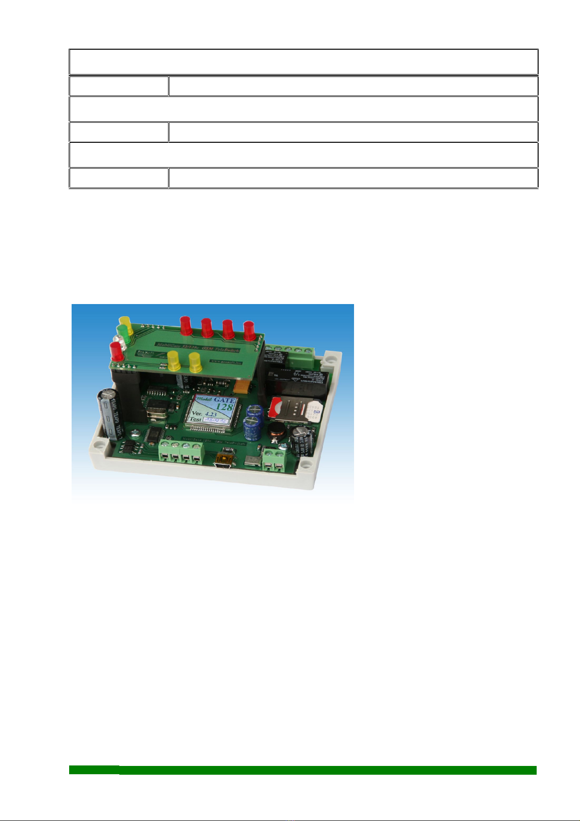
The Mobilgate-128c GSM gate
control module can be purchased in
a package with downloader
software and aerial. The panel
version is called MobilGate-128, its
enclosure version is called
MobilGate-128d and the version
that can be installed to a C-rail
(DIN-rail) with opto-isolated inputs
and with 4 pcs of high current relays
is called MobilGate-128c.
It can be equipped either with
smaller, rectangular dual-band stick
antenna or with magnetic, screwable
external antenna equipped with
RG174 SMA-connector.
2. LED diode signals
LED diodes can be found on the side of the panel in order to indicate possible error messages
in the following order:
Red "On" LED
Continuously: The interface is operational. It has to remain lit after turning it on.
White "GSM" LED
Blinking GSM module operational status. It has to light up after around 25 seconds then flash
according to its functioning. Its flashing indicated that the device is connected to the
network.
Green "Heartbit" LED
Blinking It is the life signal of the device. When the device is turned on, it does not blink until
the device is connected to the network. It starts blinking after the device is connected
to netork. The number of flashes (0 to 10) indicates the signal strength. 0 flash means
the device is not connected to network, 2 or 3 flashes mean low-signal and it occurs
when GSM connection is not secure. 4 or more flashes mean sufficient signal
strength for operation. In the case the green LED doesn’t light up after 1 minute, the
modem could not connect to the network at all. The aerial and the SIM card have to
be checked, e.g. the SIM card is protected with SIM PIN.
SeaSoft Ltd. www.seasoft.hu - www.mobil-control.eu T: (+36) 62 406405 M: (+36) 30 2557688 F: (+36) 62 405-969
Yellow "Busy" LED
Continuously It is on during device communication.
Blue "Inputs" LED
Inputs Status of inputs, indicates whether the the inputs are active.
White "Outputs" LED
White Status of outputs, indicates whether the relays are triggered.
3. Connection and installation of the MobilGate-128c
The connection points of the interface can be found in the figure below:
Up: High current relay outputs
Down: USB connectors
Input connectors
Power supply connector
The power connection needs 10-
30V DC supply voltage. The inputs
of the MobilGate-128 gate controller
can be triggered by connecting it a
5-30Vdc voltage on the opto isolated
inputs. The numbering of the module
inputs is marked on top of enclosure.
It has high current No-Com-Nc type
relay outputs and their maximalum
load is 230V and 8A. The No, Com
and Nc points of the relays are wired out. The GSM modem has a screwed SMA aerial connector
and a small-sized pole aerial or an aerial with a coax cable or similar plug can also be installed to it.
The power input of the GSM gate opener module is protected against reverse polarity and it
is equipped with 500mA multifuse. The input voltage on the general purpose inputs ranges is from
5V ... 30Vdc.
4. Configuring MobilGate-128c using a computer:
MobilGate-128c can be configured with computer or notebook via USB-port by using our
free software. A SIM card that is able to send SMS and it is not protected with PIN code has to be
isrequired for Windows XP or any newer operation system. After driver installation, the next step is
inserted into the module. When the device is connected to the USB-port, the module driver has to be
SeaSoft Ltd. www.seasoft.hu - www.mobil-control.eu T: (+36) 62 406405 M: (+36) 30 2557688 F: (+36) 62 405-969

installed from the CD or it can be downloaded from www.seasoft.hu . Installing the gate controller
module driver the serial port
configuration. It starts by clicking
the Set Port button. Windows
registers the device and assigns it
to a COM-xx port. The software
indicates module version and
enters configuration mode. The
user can configure MobilGate-128
controller freely in configuration
mode.
If the software cannot find the
port of the device indicated on the
picture, it has to be identified
manually in Windows by the
followings:
-> Control Panel -> System -> Hardware -> Devices -> Ports
The GSM device has to be identified by which serial port from Com1...Com99 it is connected to.
Manual configuration is necessary when previously a lot of USB devices had been connected or
virtual serial ports were
SeaSoft Ltd. www.seasoft.hu - www.mobil-control.eu T: (+36) 62 406405 M: (+36) 30 2557688 F: (+36) 62 405-969
configurated to the computer. In this case the device
might not be in the range of Com1...Com99. Start
the downloader software then set the Com value in
Settings -> Port configuration menu.
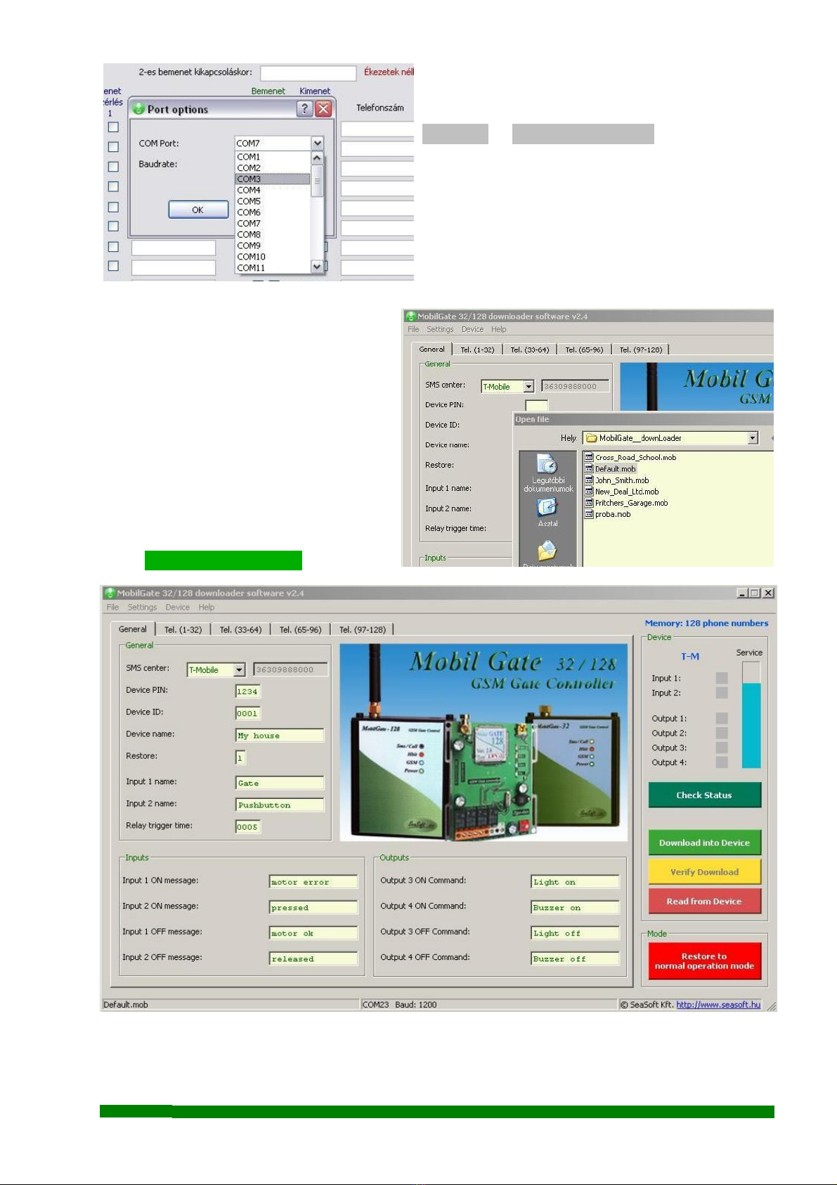
The download software of MobilGate-128c
offers a fast and simple way to configure the device.
Menus appearing on the screen allows the access to
the most important functions. Not only down-
loading the configuration into the device is possible,
but also the previously set configuration can be read
from gate controller. If the data has been modified since the last download i.e. by SMSs, it can be
read and checked. It is advised to always
start configuration with a file named
Default.mob. It is easier to edit uploaded
data without making any mistake than
creating new values. It is important to fill
out the required fields and avoid the use of
accented characters for names and
commands because the module does not
recognize accented characters. Fill the
phone numbers in international format
without the ‘+’sign! Loading data into the
device can be started by clicking the
green Dowload into Device button.
The successful download will be indicated in a pop-up window. The pop-up window contains a
corresponding error message if the download was unsuccessful.
SeaSoft Ltd. www.seasoft.hu - www.mobil-control.eu T: (+36) 62 406405 M: (+36) 30 2557688 F: (+36) 62 405-969

Unsuccessful download can happen in case of connection
failure between the computer and device. By clicking on the
button named Read from Device the previously downloaded
data can be read, and it results in overwriting data on the
screen with the uploaded data. It is advised to check
downloaded data with the yellow-colored Verify Download
button. The Check Status function queries the device for network connection status, input and
output status and possibly the name of the service provider. Relay functions can also be checked
manually. Click on
Menu -> Device -> Relay test , where relays can be triggered manually
which is shown by the output status on
screen located below the inputs’statuses.
The software can handle every version
of the MobilGate family. It automatically
recognizes the 32 and 128 version of the
device family and it allows to open the
group of mobile numbers beyond 32 in
case of the 128 version.
After finishing the configuration, please
reset the module to verify the changes. It
can be done by clicking on the red-colored
Restore to normal operation mode button
The GSM module quits configuration
mode and resets to normal mode.
After restore, it restarts automatically,
switches back to normal operational mode,
connects to the network and (after less
then a minute) when the green LED starts
to blinking, it becomes fully operational
again
SeaSoft Ltd. www.seasoft.hu - www.mobil-control.eu T: (+36) 62 406405 M: (+36) 30 2557688 F: (+36) 62 405-969

5. Configuring MobilGate-128c by SMSs
Considering that MobilGate-128c is a complicated device, it is advised to configure it with
the download software. Simple changes (e.g. adding or removing a phone number) can be done
remotely via SMS. The module confirms every SMS command with a response SMS. Do not send
any further SMS commands until the confirmation SMS is received, because it might be lost and will
not be executed! The confirmation SMS shows the changed parameter and the actual status of inputs
and outputs. If the given command is wrong, the module cannot recognize it, thus an SMS with the
content of Error! will be sent back. Please configure the SMS center number first during
configuration otherwise the device will not respond for certain configuration commands and will not
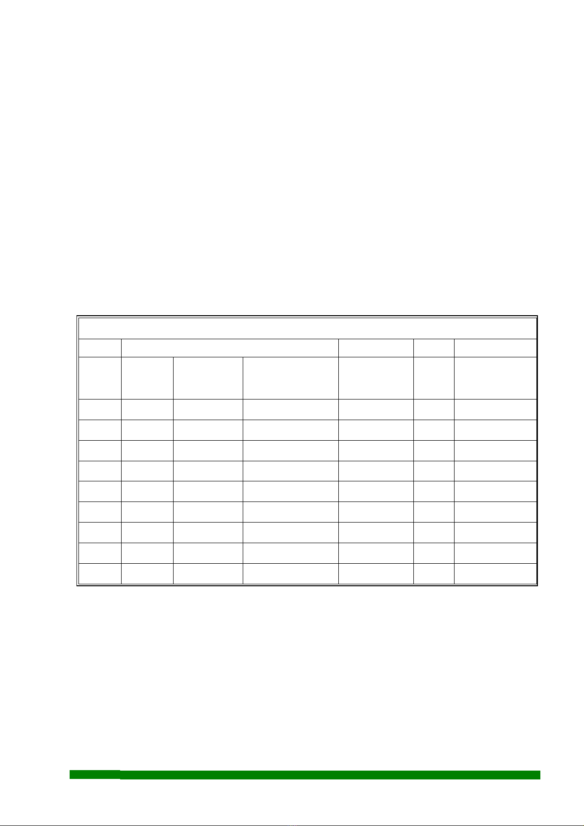
operate correctly. It is necessary to know the memory map of the device for configuration:
MobilGate-128c - functional memory map
Memory Function / contents Remarks Default Progr. samples
00 Provider's SMS center number International format - - - 36309888000
01 Device PIN code 4 characters 1234 9876
02 Device identifier 4 scharacters 0001 0007
03 Name of device Max. 16 characters My house My castle
04 Restore report of inputs 0 = no, 1 = yes 11
05 Name of input 1 Max. 16 characters Gate Barrier
06 Name of input 2 Max. 16 characters Pushbutton Alarm system
07 Relay's switch-on time Between 0...9999 sec 0005 0012
08 Switch-on SMS command of relay 3 Max. 16 characters Light on alarm on
09 Switch-on SMS command of relay 4 Max. 16 characters Buzzer on syren on
10 Switch-off SMS command of relay 3 Max. 16 characters Light off alarm off
11 Switch-off SMS command of relay 4 Max. 16 characters Buzzer off syren off
12 Switch-on SMS from Input 1 Max. 16 characters motor error barrier trouble
13 Switch-on SMS from Input 2 Max. 16 characters pressed in alarm status
14 Switch-off SMS from Input 1 Max. 16 characters motor ok barrier ok
15 Switch-off SMS from Input 2 Max. 16 characters released end of alarm
16 Reserved memory area No function - - - - - -
17 Reserved memory area No function - - - - - -
18 Reserved memory area No function - - - - - -
19 Reserved memory area No function - - - - - -
20...25 Reserved memory area No function - - - - - -
26 Reserved memory area No function - - - - - -
27 Reserved memory area No function - - - - - -
SeaSoft Ltd. www.seasoft.hu - www.mobil-control.eu T: (+36) 62 406405 M: (+36) 30 2557688 F: (+36) 62 405-969
Add the SMS center number first, because confirmation SMS will get back about its sending as
well:
i.e. !1234,W00,36309888000 where 1234 device PIN
W00 memory place means SMS center number
36309888000 SMS center number in international format
(here hungarian T-Mobile)
i.e.!1234,W01,5678 where 5678 device PIN
W01 memory place is PIN code giving command
5678 new PIN code
i.e. !1234,W02,5566 where 5566 new device ID
W02 device ID memory place
i.e. !1234,W11,syren where syren off message to be sent by the device in case of output 4
switch-off
W11 memory place is content of the SMS in case of output 4
switch-off
i.e. !1234,W29,3,2,36301234567 where 3(the first 3 characters).means that this phone number will be
informed about both input changes
2(second character) means that only relay 2 will switch on for
the given time when called.
36 30 1234 567 (last 11 characters) means the phone
number on memory place 29.
Using the two tables above with the same logic with using the correct syntax for the given
memory space, every memory space can be loaded via an SMS. Default settings remain in the
unchanged memory spaces. Loading memory spaces by SMSs can take some time, therefore it is
advised to use only for remote configuration.
SeaSoft Ltd. www.seasoft.hu - www.mobil-control.eu T: (+36) 62 406405 M: (+36) 30 2557688 F: (+36) 62 405-969
MobilGate-128c - functional memory map (continued)
Memory Function / contents Remarks Default Progr. samples
Inputs
1st character
(starts SMS)
Outputs
2nd character
(switched by call)
Telefon number
3rd - 13th character 0= none
1= only 1st
2= only 2nd
3= both (1st and 2nd)
28 2 1 1st telefon number --- 2,1,36209876543
29 3 2 2nd telefon number --- 3,2,36301234567
30 3rd telefon number ---
31 4th telefon number ---
32 5th telefon number ---
... ... ---
... ... ---
154 127th telefon number ---
155 128th telefon number ---

6. Query SMS commands:
i.e. !1234,R00 where R00 the 00th memory place of the device (see table) carrier
SMS number can be queried.
i.e. !1234,R28 where R28 the 28th memory place of the device (see table) first user
phone number can be queried.
i.e. !1234,R where R if there is no number after it, it shows device status.
Response SMS in case of Default settings:
1234 My house Gate: motor ok Pushbutton: released Light off Buzzer off
This SMS informs about: –the valid device PIN code - 1234
–the actual nema of device - My house
–the name of 1st input - Gate
–the status of 1st input - motor ok
–the name of 2nd input - Pushbutton
–the status of 2nd input - released
–the status of sms switchable relay no.3 - Light off
–the status of sms switchable relay no.4 - Buzzer off
7. Output configuration commands
i.e. Light on where Light on command is on M09 memory place command which
(see table) is the retraction command of relay 3. Relay 3 will turn on.
Attention ! The device will execute the given command if it is identical to the command given in
the memory. If the sent SMS does not match with any SMS command, the module
will send back an Error! message.
8. Further notes
Regarding to the device functionality, GSM networks and the specialty of GSM voice calls
and SMS-s, the module requires further remarks:
a) The device can be operated with any microSIM card
b) The received unknown SMS-s, including the ones sent from the carrier (including the balance check
SMS) are forwarded to the first telephone number, if the first telephone number is specified in the
configuration.
c) If a pre-paid SIM card is used and the balance reaches zero, the device can remain operational
however it cannot send further SMS-s or initiate calls. In this case it is advised to regularly check the
balance of the card.
SeaSoft Ltd. www.seasoft.hu - www.mobil-control.eu T: (+36) 62 406405 M: (+36) 30 2557688 F: (+36) 62 405-969

d) After downloading a configuration from PC via USB, the device will restart which takes 30-40
seconds, and it will be operational after registering to a GSM network.
e) All members of the MobilGate family can operate only with SIM cards that are not protected with
PIN codes. Please note that the SIM PIN is not equal to the module PIN number.
f) Before device use, the PIN code has to be removed from the SIM card.
g) By using pre-paid SIM card, showing the caller ID must be enabled. This can be performed by
contacting the carrier’s customer service.
h) Call-forwarding and SMS reminders about missed calls sent by the carrier must be disabled on the
SIM card.
9. Connecting the MobilGate-128c
10. Specifications
Power supply: 10–30 Vdc GSM: Dual band
Max. Current: 290 mA Frequency: 900/1800MHz
Stdby current (relays on): 27 mA Communication: SMS, voice
Stdby current (relays off): 135 mA Aerial conn.: SMA
Operating temperature -30 - +70 C Enclosure: DIN rail enclosure
Dimensions: 107 x 90 x 66 mm
SeaSoft Ltd. - 2013
SeaSoft Ltd. www.seasoft.hu - www.mobil-control.eu T: (+36) 62 406405 M: (+36) 30 2557688 F: (+36) 62 405-969
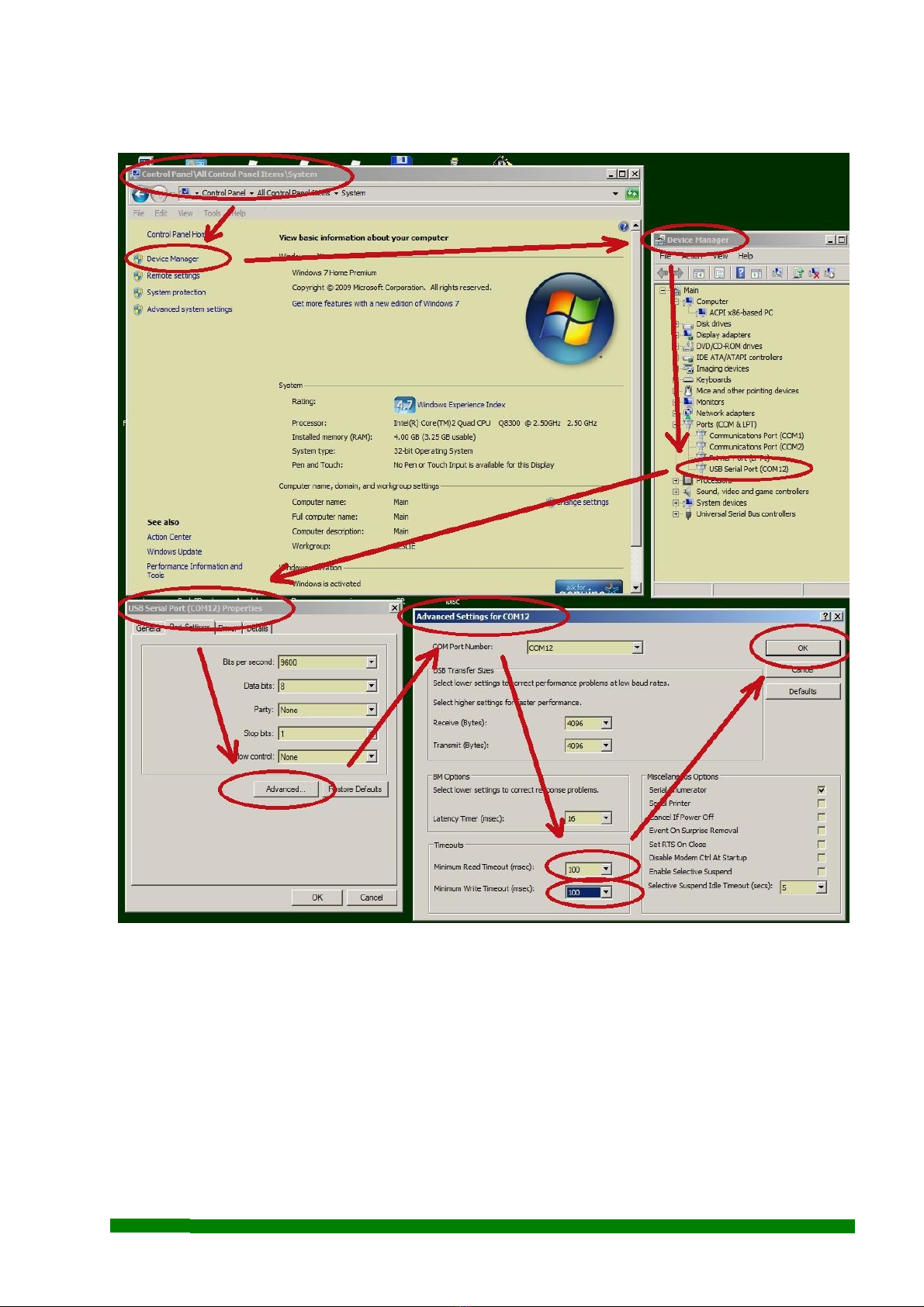
Appendix: modificatons of of setting of USB serial Com port in Windows-7 (step-by-step)
SeaSoft Ltd. www.seasoft.hu - www.mobil-control.eu T: (+36) 62 406405 M: (+36) 30 2557688 F: (+36) 62 405-969
Table of contents
Other SeaSoft Industrial Equipment manuals

Popular Industrial Equipment manuals by other brands

ABB
ABB HT584444 Operation manual

Kooltronic
Kooltronic Advantage KXRP33 Operator's manual

NeoDen
NeoDen NeoDen 3V user manual

Mayr
Mayr EAS-smartic 484.XX5 Series Installation and operational instructions

BVA Hydraulics
BVA Hydraulics HDG15002 instruction manual

Bavis
Bavis Transaction Drawer installation instructions

CWT
CWT 1736 Platinum Assembly guide

BVA Hydraulics
BVA Hydraulics CH38 instruction manual

Siemens
Siemens SINAMICS S Series List manual

Peter electronic
Peter electronic VersiSafe Speed 27810 Series Assembly instructions

ABB
ABB HT608450 Operation manual

Concoa
Concoa 632 Series Installation and operation instructions


