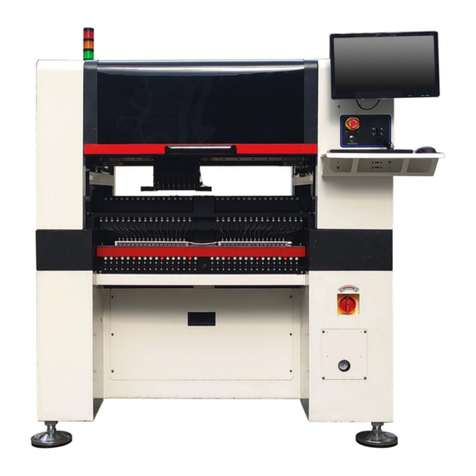
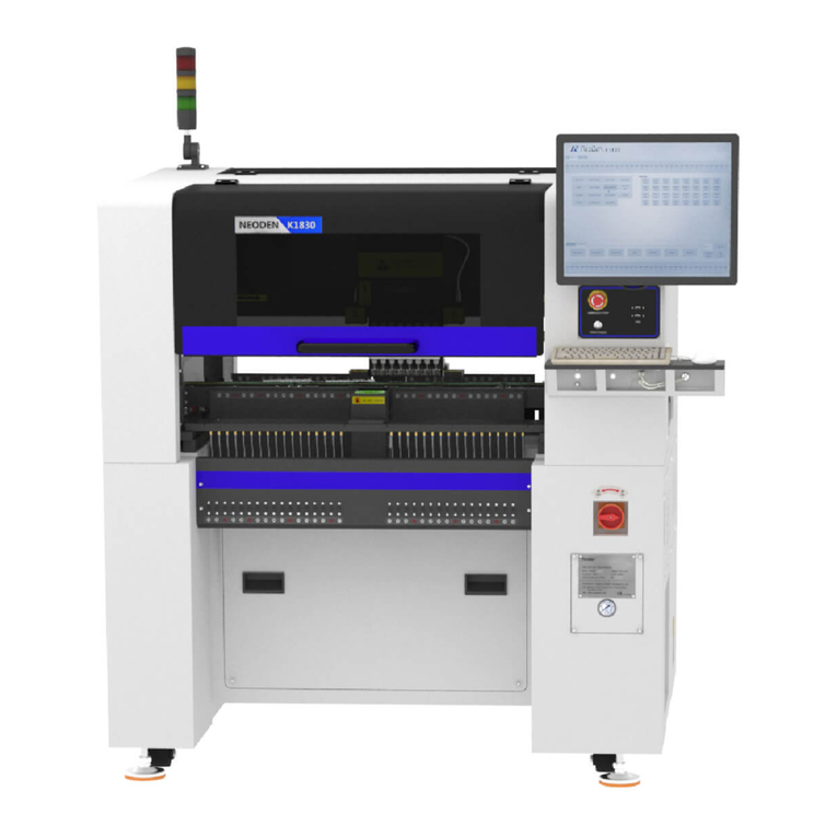
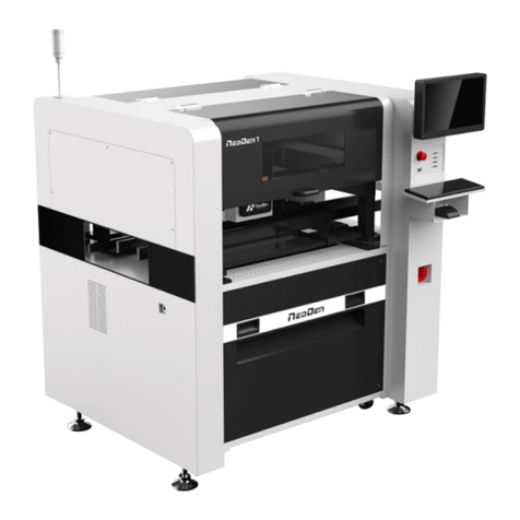
NeoDen NeoDen 3V User manual

Desktop Pick and Place Machine with Vision System
NeoDen 3V
User Manual

Content
1. NeoDen 3V Introduction..................................................................................................................................... 1
1.1. Brief Introduction..................................................................................................................................... 1
1.2. Structure of NeoDen 3V...........................................................................................................................2
1.3. Operation Flow Chart...............................................................................................................................3
1.4. Procedure for Making a Programming File............................................................................................. 4
2. Edit on the Operation Interface........................................................................................................................... 5
2.1. PCB Information Interface....................................................................................................................... 5
2.1.1. PCB Feed Setting.......................................................................................................................... 5
2.1.2. Panelized First Chip Setup............................................................................................................6
2.1.2.1. Single Board.......................................................................................................................6
2.1.2.2. Panelized Board................................................................................................................. 8
2.1.2.3. Mirror Board...................................................................................................................... 9
2.1.2.4. PCB Angle Correction......................................................................................................11
2.1.2.5. Bad Board Detection........................................................................................................ 11
2.1.3. Component Setting......................................................................................................................12
2.1.3.1. PCB Mark Setting............................................................................................................ 12
2.1.3.2. Manual Programming...................................................................................................... 14
2.1.3.3. Re-Edit............................................................................................................................. 15
2.1.3.4. Import PCB Coordinate File............................................................................................ 16
2.1.4 Feeder Settings............................................................................................................................. 17
2.1.4.1. Feeder Arrangement.........................................................................................................17
2.1.4.2. Feeder Configuration....................................................................................................... 17
2.2. File Mount.............................................................................................................................................. 21
2.3. Manual Test............................................................................................................................................ 22
2.3.1. Placement Head.........................................................................................................................223
2.3.2. Host Control................................................................................................................................ 23
2.3.3. Feeder Test...................................................................................................................................24
2.4. Factory Settings......................................................................................................................................25
2.4.1. Feeder Configuration.................................................................................................................. 26
2.4.2. System Configuration..................................................................................................................27
2.4.2.1 Default Parameters 1 Setting............................................................................................ 27
2.4.2.2. Nozzle Alignment.............................................................................................................28
2.4.2.3. Nozzle 1 and Camera Relative Position.......................................................................... 28
2.5. First Trial and Test..................................................................................................................................29
2.5.1. First Dry Run...............................................................................................................................29
2.5.2. Production Test............................................................................................................................29
2.5.3. Component Inspection................................................................................................................ 29
2.5.3.1. Inspection Items............................................................................................................... 29
2.5.3.2. Inspection Methods.......................................................................................................... 29

2.5.3.3. Inspection Standard..................................................................................................................30
2.6. Continuous SMT Production..................................................................................................................30
3. Structure and maintenance instruction.............................................................................................................. 31
3.1. Structure Chart................................................................................................................................................31
3.1.1. Peel Box...................................................................................................................................... 31
3.1.2. Tape Reel Loading.......................................................................................................................32
3.1.3. Nozzle..........................................................................................................................................32
3.1.3.1. Size of Nozzle.................................................................................................................. 32
3.1.3.2. Reference of Nozzle Selection.........................................................................................33
3.2. Maintenance........................................................................................................................................... 34
3.2.1. Reinforce Daily Maintenance..................................................................................................... 34
3.2.2. Requirement for Operator........................................................................................................... 34
3.2.3. Formulate Measures to Reduce/ Avoid Mistake......................................................................... 34
3.2.4. Maintenance of Device............................................................................................................... 35
3.2.4.1. Check Below Points Daily............................................................................................... 35
3.2.4.2. Check Below Points Monthly.......................................................................................... 35
3.2.5. Related Issues During Solder Paste Printing Process................................................................. 36
3.2.5.1. Stencil Printer Technology...............................................................................................36
3.2.5.2. Inspecting of Solder Paste Printing..................................................................................36
3.2.5.3. Instruction about Soldering Printing................................................................................37

IMPORTANT
IN ORDER TO USE THE PICK AND PLACE MACHINE
SAFELY, PLEASE READ THIS USER MANUAL
COMPLETELY AND UNDERSTAND IT THOROUGHLY
BEFORE OPERATING THIS UNIT AND RETAIN THIS
BOOKLET FOR FUTURE REFERENCE
Safety Device, Warning Label
1. Before operation, please ensure the presence of adequate guarding and safety devices to avoid accident.
2. When tear down the safety device, please keep it in the original position,and make sure it works in good
condition.
3. Please make sure the warning label can be seen clearly. If peeled off or stained, please contact us freely
for a new one. When safety device malfunctions, no running of the machine after removing safety device.
Or it will cause severe injuries and casualty accidents.
Usage
1. You agree that you will solely be responsible for your using of any products and services provided to you
and that you will use our products and services legally and only for the purposes that they are intended to
be used for.
2. You agree that you will not misuse the products and/or services supplied and that you will abide by any
laws applicable to this agreement or the operation of it.
Training
In case of any accidents that caused by improper operation, only those who have the training designated by
Neoden, equipped with proper knowledge and operation skills can operate this machine.
Notes
1. Please read this user manual completely before operating this unit and retain this booklet for
future reference.
2. The contents include all features of NeoDen 3V, some of which may not be equipped on
your machine.
3. Basic training and basic SMT knowledge is required for an operator.
4. For routine inspection and repair,please contact sales for operating instruction. During the
repairing process, please use the spare parts provided by Neoden.

CAUTION
Power off: After cut off main power supply, pull the plug or disconnect the power cable from the power supply.
1. When an exception or failure happens, or power failure,please terminate the operation of Windows,and
power it off.
2. Power off prior to cleaning and repairing in case of any accidents.
When pull the plug, please hold the head instead of wire.
Attention Should be Paid to During the Procedure
Transport
Please take necessary security measures to prevent upside down or fall when lifting or moving.
Open
1. Please read all instruction in the wooden box.
2. Do not cut the packing tape by knife to avoid scratch the machine.
3. Keep all packing material.
Installation
1. Please put the machine in a horizontal place.
2. Please keep the floor clean and dry, and the machine should be grounded, to prevent electric shock or
leakage.
Prepare Work
1. Make sure the power cable no damage, no shedding and no loose.
2. Keep hands off the working area.
Maintenance
1. Repair and calibration should be operated by skilled mechanical technician.When replacing parts,please
use the part which are supplied by NeoDen.We are not responsible for any accident result from using
nonstandard part.
2. In order to prevent electric shock caused by unskilled operation,the electrical
repairs,maintenance(including wiring),should be operated by professional electrician or the technical staff
from NeoDen or our distributors.
3. Make sure Bolts - Nuts are tighten after repair,calibration or replacing any part.
Working Environment
1. Do not use machine in a noisy environment,such as high frequency welding machine.
2. Do not use machine if the power supply voltage exceed the rated voltage ± 10%. Do not use machine and
pull the plug when thunder to avoid any accident caused by damaged electrical component.

1
1. NeoDen 3V Introduction
1.1. Brief Introduction
Compared with the previous version TM245P, NeoDen 3V adopts a high-definition camera that could
mount most kinds of components including micro chips like 0402, fine-pitch ICs like QFN and so on; and with
high speed and accuracy, small volume, low power, stable performance and easy operation, NeoDen 3V
committed to create the greatest value and try to fulfill all demands for customers in the actual production.
Number Of Heads
2
Placement Accuracy
0.02mm
Placement Rotation
0~360°
Placement Rate
5000CPH (vision off); 3500CPH (vision on)
Placement Area
320*390(X、Y)(feed from the left side and back side)
Vision System
yes
Nozzle Type
CN040/CN065/CN100/CN140/CN220/CN400/CN750
Applicable Components
0402-5050,SOP, TQFP and so on
IC Tray feeder
10
Vibration Feeder
5 ( customization supported)
Feeder Type
8mm、12mm、16mm、24mm
Feeder Capacity
46( all 8mm in width)
Position Accuracy
0.02mm
Power
160~200W
Electricity Supply
AC 220V/110V
Machine Size
820(I)*680(W)*410(H)mm
Weight
60KG

2
1.2. Structure of NeoDen 3V
⑦
⑧
①
②
③
④
⑤
⑫
⑥
⑨
⑪
⑩
⑬
Each part mentioned above can be disassembled and maintained. Please find more details on Chapter 3.
①:Start/Pause Button
②:On/off Button
③:Emergency Button
④:USB Connector
⑤:Fixation Holder
⑥:Head
⑦:Needle
⑧:Nozzle
⑨:Backward Fixed Block
⑩:Feed Chute
⑪:Peel Box
⑫:Vibration Feeder
⑬:Reel Holder

3
1.3. Operation Flow Chart
NO.
Flow Chart
Remark
1
Checking the working area whether it is safe or not
2
3
Machine will start a 1-2 mins self-inspection process after
boot-up. The head will travel along in X&Y axis. It will
enter the operation page once finished.
4
5
Plz refer to the detailed programming tutorial in Page5
6
After making a programming file, there may exist several
programming issue, such as rotation issues of
components, thus a production testing is necessary for
solving issues.
7
Start to pick and place.
8
Production finish, exit.
9
Shut down the system via computer, then power off the
machine.
10
Disconnect the electricity supply after the system being
powered off.
11
Keep the machine clean, daily maintenance of the nozzles
to assures its high utility.
System power off
Power off
Cleaning and
maintenance
Exit
Mounting
Preparation
Turn on
Initialization
Operation page
Edit
Yes
Test
Modify
No

4
1.4. Procedure for Making a Programming File
Chip list settings
Select a file and start working
Start
Panelized PCB first chip setup
Edit
PCB feed setting
Mark point settings
Feeder settings
Save and cancel
See P6
See P12
See P16
See P20
See P5
See P5
Note: Above the procedure for making a programming file, the basic procedure of manual programming and
importing coordinates file directly are similar. Please find the detailed operation steps of the differences on
relative page.

5
2. Edit on the Operation Interface
2.1. PCB Information Interface
See below Fig.: Edit Interface
Create a new file or choose a file and enter the edit page
2.1.1. PCB Feed Setting
Function: This part is used to confirm the feeding place, the first edit item in manual program. Feed the PCB to
the estimated position and adjust it by click”Align”

6
2.1.2. Panelized First Chip Setup
Function: This is mainly to determine the first component position on single or panelized PCB. The principle is to
collect and calculate the data of each board’s relative spacing, in order to achieve the effect of the actual placing.
2.1.2.1. Single Board
Single board: Just need to find the first component (in chip list) actual position on board by clicking “Align”
button, it will skip into below screen under vision. Make sure the cross hair is in the center of bonding pad, this
component will be locked, then save.

7
After saving the coordinate, the screen will automatically turn back to “PCB information” . Click “Create
panelized list” to get the information of this board. Now we’ve finished setting of first component of Single board.

8
2.1.2.2. Panelized Board
The sequence is same to single PCB, but please pay some attention to several points below.
The row and column is determined by the positioning of PCB on working area. The horizontal direction is
the column. Enter data in the row and column.
About the data collection of “left bottom” , “left top” and “right top”, we should take the
“left bottom” as the basic, and then go to set “left top” and “right top”. Once all the data is collected, the
machine can calculate and process the information of panelized PCB.
Please refer to the data collecting method of each position information as following:
The data of “left bottom” is collected according to first component in programming file. Press “align” find
the left bottom panel which is nearest to the feeding entrance, after saving the data, it will return to the “PCB
information” automatically.
The data of “left top” is collected according to component ( the component is same to that on “left bottom”).
Press “align” find the left top panel which is furthest to the feeding entrance, after saving the data, it will
return to the “PCB information” automatically.
The data of “right top” is collected according to component (the component is same to that on “left bottom”).
Press “align” find the right top panel which is furthest to the feeding entrance, after saving the data, it will
return to the “PCB information” automatically.
After setup, click “create panelized list”, the data will be generated accordingly in the blank. You can also
double-confirm each position by clicking” Align”. ( Note, the three positions must be the same component from
different panelized board)

9
2.1.2.3. Mirror Board
Mirror board includes row panelized PCB and column panelized PCB
Row panelized: several same PCBs are arranged in horizontal direction, and the nearby rows are mirrored
Column panelized: several same PCBs are arranged in vertical direction, and the nearby columns are mirrored
4
4
4
4
4
1
1
1
2
2
2
3
No.1 red areas are original ref
No.2 yellow areas are original boards
No.3 blue area is mirror ref
No.4 light blue areas are mirror boards

10
4
4
4
4
4
1
1
1
2
2
2
3
No.1 red areas are original ref
No.2 yellow areas are original boards
No.3 blue area is mirror ref
No.4 light blue areas are mirror boards
Based on actual board to choose an applicable model of panelized mode. Image left side
is the arrangement way of mirror board and right side is the mirror board showing on computer.

11
2.1.2.4. PCB Angle Correction
PCB angle will influence the accuracy of mounting. The angle more closer to 0 degree the better, and the angel
deviation need to be within 1 degree.
The angle of PCB is generated according to panelized PCB coordinates, but we can also adjust the angle by
manual. Click” PCB angle” button, according to the index of machine to choose two points, then a new PCB angle
will be generated.( Note, the two points need to be in one vertical or horizontal line)
Under panelized PCB mode, “ PCB angle” is locked. You need to correct from panelized PCB to single PCB( 1*1),
after confirm the PCB angle, you can change back to panelized PCB model.
2.1.2.5. Bad Board Detection
In actual work,bad boards no need to be mounted, then, you can activate this function to skip these boards
automatically.
Processes of detecting bad boards,
1) According to panelized PCB to generate panelized list
2) Choose” Auto” from “ Skip” options of panelized list
3) Click” Align” button to choose one fixed position and mark it, thus every time when machine scans this mark,
it will skip this bad board.( One common guideline is stick another colorful tag on the bad board, if stick with
this tag the machine will skip the bad board, otherwise it will go on mounting)

12
2.1.3. Component Setting
2.1.3.1. PCB Mark Setting
Function: After completing setup of the mark points, with which the machine can locate the position of PCB and
identify the set up mark points, so that the next step can be followed
Mark Point on Single PCB
This mainly applies on single PCB or a whole board that consists of a few same boards (take them as a single
board ). Generally we need to set 2-3 mark points.
Mark Point on Panelized PCB
This mainly applies on multiple, identical PCBs, that is to say when mount each small panelized PCB, machine
will scan mark points of each small panelized PCB.
The biggest advantage is, if each small panelized PCB has a little angle deviation, use panelized PCB mark point,
it will reduce the deviation during pick and place.
Alignment of Mark Point
Alignment includes:align automatically and align manually.
1) Align automatically, find two mark points from PCB, during the mounting, it will know the position of PCB
from aligning the two mark points
2) Manually align, if there is no mark point on PCB, you can use some positioning holes or some other
referential points as subsidies to locate the PCB.
Import Coordinate
According to the PCB schematic, you can get the coordinates of mark and write down manually. Moreover,
you can see “Min” ,“ Max”, “Light ”, “Brightness” from Mark point list.
1) “Min”, “Max” are the minimum and maximum size of mark point, a floating value to make sure you can get
the correct mark points
2) “Light ” includes inner circle and outer circle. If use one hole as mark point need to choose inner circle of
light source, if use bright spot as mark point need to choose outer circle of light source
3) ‘Brightness”, in general, use the default value( You can change the value when necessary)

13
Manual Programming
When it’s in Manual Programming status, the function “Alignment” of Mark will be effective. Click on it, the
camera will go and collect the coordinate of mark, save it and go back. (Note: if the mark point is far away, please
use Overall movement to find it)
Align by manual:if there is no mark point on PCB, you can choose this mode.Note:Select two components,the
first one and the other one which can be recognized easily and far from the first component as Mark point.After
start mount,have to confirm Mark by manually.
“Min”, “Max” are the minimum and maximum size of mark point, a floating value to make sure you can get the
correct mark points
“Light ” includes inner circle and outer circle. If use one hole as mark point need to choose inner circle of light
source, if use bright spot as mark point need to choose outer circle of light source
New or Delete
New:add the quantity of mark points
Delete :delete error or useless mark point

14
2.1.3.2. Manual Programming
Select “Chip list” to start manual programming.
Function: it’s used to display footprints, coordinates, angles and sequences of components. You can choose to
manually add these information or import coordinates file directly.
Chip List Setup
First, tick the box in front of “Manual”, you will see an example of component in chip list. You can click ”Align”
to locate this component’s position and revise it accordingly.

15
You can use Nozzle 1,Nozzle 2,needle to for workbench movement. Or you can use down-looking camera for
visual minor adjustment.
Locate the component’s center as coordinates, click “Save” and return to Chip list. Then you can fill the left
information of components(note: designator, package, foot print and angel. The angel of horizontal component is
0°or 180°, the angel of vertical component can be different from +90°to -90°according to its polarity(Active
Components) . All the angel value should be integer.
After completed all information for the first component, you can click “New” to create a new component. Its
default coordiantes will be same to previous one, you just need to click “align” and relocate its correct position,
save the data and back to fill the left information.
Sequence of Components
You may have to rearrange the sequence of components after programming, here are 3 ways available.
1) Move up: select the component and click “up” to move it up.
2) Move down: select the component and click “down” to move it down.
3) Move to first place: select the component and click this button to move it up to the first place.
2.1.3.3. Re-Edit
Function: it’s used to edit the file after you have find there is an offset due to the board twisting.
Either import coordinate file or manually programming, you can edit the file by using this button.
1) Please advance the board to the setup position, then click “Feed” in PCB feed settings.
Table of contents
Other NeoDen Industrial Equipment manuals
Popular Industrial Equipment manuals by other brands

Remote Solution
Remote Solution SAFE-T-RACK SR-U SDB-15VCPW-1223 Operation manual

Look Solutions
Look Solutions Cryo-Gate operating manual
Danfoss
Danfoss EC-LTS1200-410 user guide

SEW-Eurodrive
SEW-Eurodrive CM3C63 Series Addendum to the operating instructions

Dell
Dell PowerVault 124T LTO-3 user guide

DEPURECO
DEPURECO miniAIR Series Use and maintenance manual

Sumitomo
Sumitomo Y-OP4-U Instruction manual for assembling and operation
YASKAWA
YASKAWA Motoman DX200 Operator's manual
Trotec
Trotec DH 25 S Original instructions

McHale
McHale C4 Series Operator's instruction manual
Tronair
Tronair 06-5042 Series Operation & service manual

Rohm
Rohm RB-K operating instructions
