SeaSoft MobilSwitch-Micro-C User manual
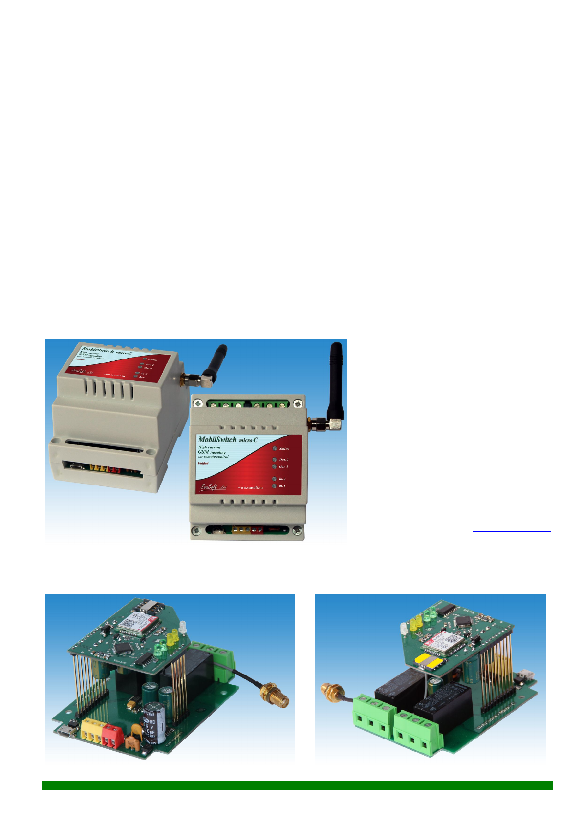
MobilSwitch-Micro-C Industrial GSM signalling and remote control module
with 2 inputs and 2 high current relay outputs
The MobilSwitch-Micro-C module is a general, industrial-grade GSM module, developed for remote
signaling and remote control. It has 2 inputs which are activated by voltage-less contact, and it has 2high
voltage and high current relay outputs. It can be programmed with its own software called "Unified" from
any PC or notebook. The device notifies the users via pre-configured SMS-s and voice calls, and it has an
optional acknowledging function. The relays can be triggered by user-configured SMS-s or free voice calls
for dedicated users. The relays can be configured to operate in monostable mode (after switching on, the
relays are turned off automatically within a time interval) or bistable mode. (switching the relays on and off
are performed with separate commands). It can be programmed for max. 8 phone numbers, and can be used
as a GSM remote signaling, remote controlling device, either for industrial purposes or home applications,
such as remote signaling and controlling security device. The power supply of the device has industrial input
range of 10V-30V DC and draws min. 500mA current. The carrier's SMS-s can be forwarded to the user-
configured phone number, and the device operation can be checked with its built-in signal-of-operation
function. It has two variants: either with built-in aerial or RG-174 magnetic aerial with SMA connector.
1. Operation:
The module holds its configured and
programmed data even after power-off. In
the case of carrier problems or cellular
signal loss, the device switches itself off
then on, re-connects to cellular network
and restores normal operation. The device
comes with an enclosure and carrier-
independent GSM module in DIN rail
enclosure with a small SMA connected
aerial or with external magnetic antenna.
The device comes with our free
configuration software that can be down-
loaded from website: www.seasoft.hu
Our devices can be configured with any
PC-s with a single micro-USB cable. The MobilSwitch-Micro-c has a carrier-independent, industrial-grade
GSM module that can be operated with any prepaid or subscription-based nanoSIM cards. The low voltage
low-current variant is called MobilSwitch-Micro, or Micro-a and available also with two antenna-variations.
SeaSoft kft. www.seasoft.hu www.mobil-control.eu T: (62) 406-405 M: (+36) 30 255 7688 F: (62) 405-969

2 . Setup:
To ensure proper setup of MobilSwitch-Micro-c, the following instructions should be performed in order:
1The SIM PIN must be removed from the SIM card
2
3
4
By inserting the SIM card into a traditional mobile phone, the SMS-sending
ability of the card must be checked. Newly issued SIM cards have an initial
credit that can only be used for voice calls, thus the SMS-sending ability is
enabled only after topping-up the card. Call-forwarding has to be disabled.
Carrier-issued SMS-s for missed calls must be disabled too. In the case of
prepaid cards, displaying the caller-ID functionality must be enabled via the
carrier customer service (enabling the “show caller-ID” option in the
settings of a handheld mobile phone is not sufficient when using prepaid
cards).
The nanoSIM card has to be inserted in the correct position into its slot
located at the back of the module, as shown in the figures.
The power supply has to be connected in a polarity-correct position. After
power-on, the device connects to a cellular network. The green LED blinks
periodically after the device is successfully initialized.
5The configurator software can be either launched from the installation CD
or can be downloaded from our website www.seasoft.hu. The software can
be simply launched, there is no need for software installation.
6After launching the “Unified” configurator software, the device should be
connected to the PC with a microUSB cable.
7The software automatically recognizes the device family and device type,
and it shows its picture along with its wiring instructions. The software
automatically loads the default configuration parameters.
8It is advised to query the status of the device (state of inputs, outputs,
supply voltage, signal strength, etc.) to check if the device is registered to
the GSM network. After downloading the configuration, the USB should be
detached before powering the device off.
9After downloading the configuration and powering the module off, it should be turned on again and the overall
functionality based on the configuration should be tested thoroughly.
3. Description of LEDs:
- Yellow (continous): After power-on, the yellow LED is on for approximately 10 seconds. During this period, the
GSM is initialized. While the module is searching and registering to a GSM network, the yellow
LED blinks. After approximately 40 seconds, the yellow blinking stops and turns into green.
- Green (blinking) The frequency of the blinking reflects the signal strength. More blinks within a period mean
greater signal strength.
1 blink than pause - very weak signal, module sometimes disconnects from network, it is
advised to relocate the device.
2 blinks than pause - weak signal, device may disconnect from network which results in
approximately 30 seconds of outage while the device restarts
3 blinks than pause - medium signal strength, device is capable of stable operation
4 blinks than pause - strong signal, device is capable of stable operation
5 blinks than pause - maximum signal strength
- Yellow (blinking) The yellow LED is blinking during network communication (SMS or voice communication).
- Red (fast blinking) The module cannot find GSM network or antenna is faulty. It may also indicate the followings:
SIM card error, SIM PIN is not disabled, SMS or voice modes are disabled on SIM card.
SeaSoft kft. www.seasoft.hu www.mobil-control.eu T: (62) 406-405 M: (+36) 30 255 7688 F: (62) 405-969

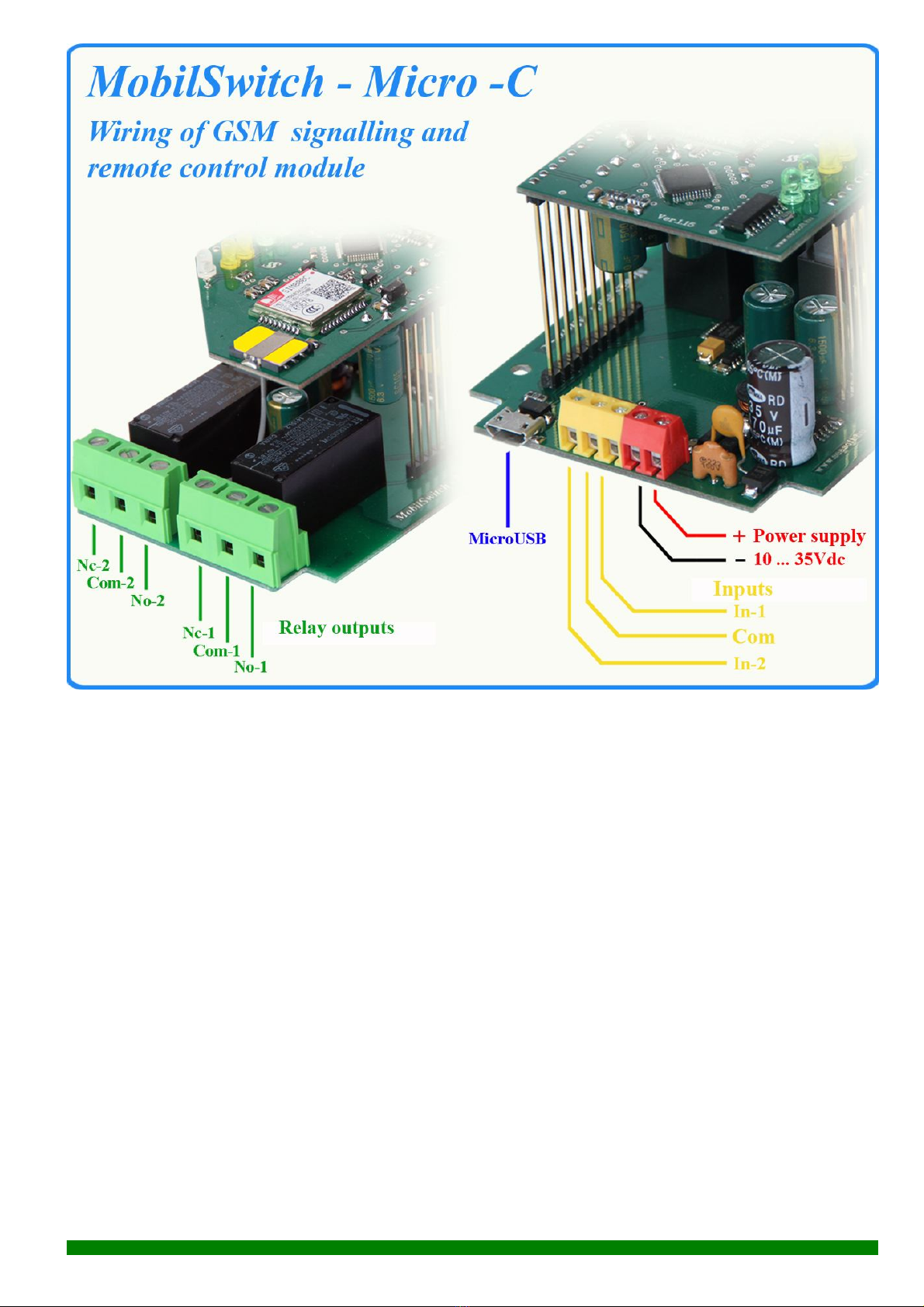
4. Device wiring:
The device requires +10-30V DC power supply with at least 500mA power supply connected to the red
connectors which is equipped with polarity
protection. The contact inputs are triggered
with 0V,i.e. pullingthem to ground. It is
forbidden to connect more than +5V to the
inputs in case they are driven by open-
collector lines. Both relay output are a high
voltage high current "No-Com-Nc" types.
The maximum load of relay outputs cannot
exceed 6A at 250Vac. The inputs of device
are equipped with noise protection,
however external voltage mus'nt be applied
to them. Inputs can be triggered with small-
resistance (and without contact-bouncing)
contacts, switches, and relays. The module
is equipped with a standard nanoSIM
holder. The module can be programmed
and configured with a microUSB cable.
5. Device configuration from PC:
The MobilSwitch-Micro-c GSM device can be fully programmed and configured with our universal
SeaSoft kft. www.seasoft.hu www.mobil-control.eu T: (62) 406-405 M: (+36) 30 255 7688 F: (62) 405-969

downloader software called "Unified" via a microUSB cable. After powering on the device and plugging
in the USB cable, all Windows operating systems (Windows XP, 7, 8, and 10) automatically recognize the
the connected device. Our universal software handles and configures all products from the MobilSwitch,
MobilArm and MobilGate product families. The software automatically recognizes the type of the connected
device and it shows its image. The status of the device, including the carrier information, status of the inputs
and outputs can be queried by pressing the "Get Status"button. All the user parameters can be edited,
however it is advised to keep the original format and change the factory values only when necessary. When
the module receives an SMS from the carrier or other unknown number (e.g. advertisements), it forwards to
the telephone number that can be set under the #020 memory location. Filling the first telephone number is
mandatory, the rest are optional, they can be left empty. Under the #016 - #019 memory locations, it can be
specified which telephone numbers should receive an SMS notification when an input has changed. Each
memory location has a short description located at the bottom. Please fill the configuration values with care
and do not use accented or special characters. All telephone numbers must be given in the international
telephone number format. The edited configuration can be saved to a file and loaded whenever necessary.
The configuration data can be downloaded to and read from the device. The software displays a
notification when the configuration was successful and shows an error message notification upon download
or read failure.
6. SMS commands:
The device can be programmed remotely with fixed-format SMS commands. :
- Query command: #?*
Response SMS: MobilSwitch-Micro Ver:1.22 T-MobileH Rssi:4 Ubat:13.0V A:1,
00:10:00 Panik button:0 Burglary system:0 Siren:0 Lamp:0
where: Ver.: 1.22 - firmware
T-MobileH - provider's name (here hungarian)
Rssi:4 - signal quality
Ubat:13.0V - power supply in Volts
A:1 - modul is active(1) or passive (0)
00:10:00 - time of temporary disarmd
Panic button:0 - status of 1st input
Burglary sysetm:0 - status of 2nd input
Siren:0 - status of 1st output
Lamp:0 - status of 2nd input
SeaSoft kft. www.seasoft.hu www.mobil-control.eu T: (62) 406-405 M: (+36) 30 255 7688 F: (62) 405-969

No. Function of memory Factory settings: User settings:
001 Provider's SMS central +36309888000
002 Maximal number of sent SMS in 2 hours 20
003 SMS command of modul's ARM status Arm
004 SMS command of modul's DISARM status Disarm
005 SMS command of time of temporary disarmd Pause
006 Time of temporary disarmd 01:59:00
007 Time interval opf automatic test 72:00:00
008 1st (master) phone number +36 30 1234567
009 2nd phone number
010 3rd phone number
011 4th phone number
012 5th phone number
013 6th phone number
014 7th phone number
015 8th phone number
016 Functions when input no.1 is "ON" V1,S1
017 Functions when input no.1 is "OFF" V1
018 Functions when input no.2 is "ON" V1,S1
019 Functions when input no.2 is "OFF" S1
020 Functions for service SMS messages R1,S1
021 Functions when comes a call from an unknown user S1
022 Name of 1st input Panic button
023 SMS message when input no.1 is "ON" pressed
024 SMS message when input no.1 is "OFF" released
025 Name of 1st input Burglary system
026 SMS message when input no.2 is "ON" Alarm
027 SMS message when input no.2 is "OFF" Restore
028 Name of 1st output Siren
029 SMS command to switch "ON" the output no.1 Sound on
030 SMS command to switch "OFF" the output no.1 Sound off
031 Name of 2nd output Lamp
032 SMS command to switch "ON" the output no.2 Switch on
033 SMS command to switch "OFF" the output no.2 Switch off
034 Functions in case of a call from a dedicated user A1,Z2,Z3,Z4,Z5,Z6
035 Timing of output relay 00:00:05
036 Functions in case of acknowlidge requirements
037 SMS message in case of a call of an un-dedicated user Unknown caller
099 Status 1 Non editable !
500 Type of module MobilSwitch-Micro Non editable !
501 Firmware 1.28 Non editable !
502 Signal quality 4 Non editable !
509 Proider's name T-MobileH Non editable !
510 Power supply 13.0 Non editable !
SeaSoft kft. www.seasoft.hu www.mobil-control.eu T: (62) 406-405 M: (+36) 30 255 7688 F: (62) 405-969

- Set output command Sound on
(now input 1st switched on, look memory #029)
Response SMS: MobilSwitch-Micro-c Ver:1.22 T-MobileH Rssi:4 Ubat:13.0V A:1,
00:10:00 Panic button:0 Burglary system:0 Siren:1 Lamp:0
Warning ! Please note that the device only recognizes the SMS command if the sent SMS command is completely
the same (letter by letter) as the command located in the appropriate memory location of the device. In
case the sent SMS command does not match any of the commands, the device will not process the
command and will forward the SMS to the telephone number located in the #029 memory location.
- Enable alarm command: Arm
(Memory #003) where: A:1 - After receiving the SMS, the module will be armed and all input
changes will trigger notifications
- Disable alarm command: Disarm
(Memory #004) where: A:0 - After receiving the SMS, the module will be disarmed and input
changes will NOT trigger notifications
- Pause command: Pause
(Memory #006) where: 01:59:00 - reflects the mute duration. Within this duration, the module
does not send notifications upon input changes, however it is
still capable of sending response SMS-s.
- Re-program memory command: *022#Panic trigger*
where: 022 - memory address
Panic trigger - the new value of memory
- Read memory location command: *022#?*
Response SMS: *022#Panic trigger
7. Miscellaneous and other information:
a. The device is operational with any (nano)SIM card
b. The received SMS-s from the carrier and unknown numbers are forwarded to the telephone
number specified under the #020 memory location. Therefore, if a prepaid SIM card is used,
the balance status SMS-s are also forwarded to this number. When the prepaid SIM card
reaches zero credit, the device is still functional, however it is unable to send SMS-s.
Consequently, it is advised to regularly check the credit balance of the SIM card.
c. After disconnecting MobilSwitch-Micro GSM signaling and control device from the PC, it
restarts itself, which lasts approx. for 40 seconds while the module searches and registers to
the carrier network.
d.The PIN protection must be removed from the nanoSIM card prior to usage. The device only
works with nanoSIM cards that are not PIN-protected.
SeaSoft kft. www.seasoft.hu www.mobil-control.eu T: (62) 406-405 M: (+36) 30 255 7688 F: (62) 405-969
8. Specifications:
Range of power supply: 10 - 30 Vdc Frequency: 800/900/1800/1900MHz
Lowest current consuption: 32 mA Communication: SMS, voice
Current consuption when relays on: 52 mA Max. voltage on inputs: +6 V max.
Mean consuption (24hours): 70 mA Aerial connector: SMA
Max. conpuption: 192 mA Ambient temperature -30 ... +70 C
Vertical size of enclosure: 90 mm
Vertical size with aerial: 119 mm
Vertical size of magnetic aerial: 110 mm
Horizontal size of enclosure (with wings): 70 mm
Enclosure Z size: 66 mm
SeaSoft Ltd. - 2017
SeaSoft kft. www.seasoft.hu www.mobil-control.eu T: (62) 406-405 M: (+36) 30 255 7688 F: (62) 405-969
Table of contents
Other SeaSoft Industrial Equipment manuals


