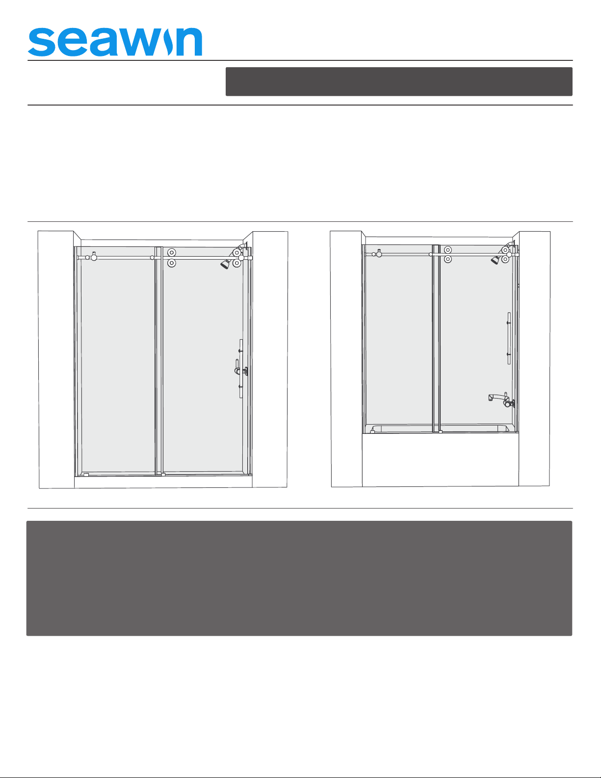
Seawind COSMO SW0115 User manual

INSTALLATION GUIDE
COSMO ™ SHOWER/TUB DOOR
MODEL NUMBER: SW0115, SW0215
Shower Enclosure Tub Enclosure
Thank you for purchasing our shower door. We hope that our product
will provide you with a satisfying experience for many years to come.
Prior to installation, examine all boxes and packages for shipping
damage and compare to packing slip. If the unit has been damaged, has
inishing defect, or has missing parts, then please contact our customer
support department. Read the instructions carefully because it contains
installation instructions about proper installation of the unit. If you do
not follow the steps correctly, then it might aect the unit’s proper use
and void the warranty. If you have any questions, then please call our
customer support department.
Local plumbing codes vary by location. You should consult with a local
licensed plumber regarding proper installation to comply with local
building codes.
Before installations make sure the surface is leveled and has the strength
to support the weight of the unit. Also make sure that the walls are at
the right angles. Irregular installation surface level, radius corners,
or improper angles of side walls will result in serious problem for your
installation. Please note that some adjustments and drillings might be
necessary during the installation process.
844-7-SEAWIN
www.seawinglobal.com
ATTENTION: PRIOR TO STARTING THE INSTALLATION, PLEASE READ THROUGH THESE INSTRUCTIONS. THIS WILL
HELP AVOID ANY UNNECCESARY DAMAGE. ANY BREAKAGE DUE TO HANDLING OR INSTALLING THIS ENCLOSURE
SYSTEM IS THE RESPONSIBILITY OF THE INSTALLER AND IS NOT COVERED UNDER THE SEAWIN WARRANTY. SEAWIN
RECOMMENDS THAT TWO PEOPLE ARE USED TO INSTALL THIS SHOWER ENCLOSURE SYSTEM DUE TO THE WEIGHT AND
FRAGILITY OF THE GLASS PANELS. SEAWIN RECOMMENDS THE INSTALLATION TO BE PERFORMED BY SOMEONE
FAMILIAR WITH THE CONSTRUCTION REQUIREMENTS FOR THIS TYPE OF PROJECT AND CARE NECESSARY FOR
THE SAFE INSTALLATION AND OPERATION OF PRODUCT.
PLEASE PROTECT ALL PRIMARY GLASS SURFACES OF THE PRODUCT. NEVER PLACE THE GLASS DIRECTLY ONTO A
TILE SURFACE. LEAVE CORNER PROTECTORS IN PLACE UNTIL NECESSARY TO REMOVE THEM. NEVER PLACE OR LEAN
GLASS ON ITS CORNERS EVEN THOUGH IT HAS PROTECTORS ON. ALWAYS USE PIECE OF WOOD OR CARDBOARD TO
PROTECT THE BOTTOM EDGE AND CORNERS OF THE GLASS PRIOR TO AND DURING INSTALLATION.
IF YOU NEED REPLACEMENT PARTS OR HAVE INSTALLATION QUESTIONS, PLEASE CALL OUR CUSTOMER
SERVICE REPRESENTATIVES.
SEAWIN RESERVES THE RIGHT TO CHANGE AND ALTER PRODUCTS ANYTIME WITHOUT PRIOR NOTICE
FOR PRODUCT IMPROVEMENT AND BETTER CUSTOMER EXPERIENCE.
INSTALLATIONS SHALL BE MADE ACCORDING TO MANUFACTURER'S INSTRUCTIONS AND DRAWINGS.
PLEASE REFER TO THE MODEL'S WEBPAGE ON WWW.SEAWINGLOBAL.COM FOR THE LATEST TECHNICAL
DRAWINGS, INSTALLATION MANUALS, WARRANTY INFORMATION OR ADDITIONAL PRODUCT DETAILS.
844-7-SEAWIN

2
20
12
4
14
COSMO™ SHOWER/TUB DOOR - MODEL NUMBER: SW0115, SW0215
PARTS- EXPLODED VIEW
CAUTION: Risk of injury or product damage. Do not attempt to cut tempered glass.
WARNING! Never use Door Handle to support yourself. This is for towels or wash cloths only.
41
7
3 9 9 9 39 1816 162 218
7
14
5
6
17
19
13
10
17
16817 1616 11
1
2
3
4
5
6
6
7 14
15
18
19
20
8
169
1710
11
12
13
FIXED DOOR
SLIDING DOOR
DOOR RAIL
ADJUSTABLE GLIDING WHEEL
ADJUSTABLE DOOR STOP
FIXED DOOR HOLDER
DOOR RAIL WALL CONNECTOR
“U” SEAL WITH 90 DEGREE VINYL FIN
SCREW ST5x50
FLOOR ANCHOR
BOTTOM MOUNT BRACKET SCREW COVER
END CAP SCREW COVER
DOOR GUIDE
SCREW ST4x25
BOTTOM MOUNT BRACKET
WALL ANCHOR
THRESHOLD
THRESHOLD END CAP
HANDLE
“U” SEAL WITH BULB ATTACHMENT

3
COSMO™ SHOWER/TUB DOOR - MODEL NUMBER: SW0115, SW0215
PARTS LIST
PLEASE STOP THE INSTALLATION AND CONFIRM WITH FACTORY IF THE ACTUAL NUMBER OR TYPE OF PARTS IS DIFFERENT!
Tape Measure Pencil Phillips Screwdriver Drill bit (Ø=1/4”) Drill bit (Ø=1/8”)
Caulk GunElectric Drill Level
Safety glassesMallet
Miter saw
TOOLS REQUIRED
19 20
x1 x1
5
10
3
8
13
1
6
11
16
2
7
12
4
9
14 15
17 18
Fixed Door Holder
x2
x1
x1
x1 x2
x1
x2
x1
x3
x1
x2
x1
x4
x1
x2
x2
x2
x3
Fixed Door
Sliding DoorAdjustable Gliding Wheel
Adjustable Door Stop
Door Rail Wall Connector
Door Guide
Threshold Threshold End Cap Handle
Screw ST4x25 Screw ST5x50
“U” Seal With Bulb Attachment
“U” Seal With 90 Degree Vinyl Fin Wall Anchor
Floor Anchor
Door Rail
Bottom Mount Bracket
Bottom Mount Bracket Screw Cover End Cap Screw Cover
Drill bit (Ø=5/16”) Drill bit (Ø=3/16”)
Installation Guide Ver 10. 03/2021

4
COSMO™ SHOWER/TUB DOOR - MODEL NUMBER: SW0115, SW0215
IMPORTANT INFORMATION:
Determine if your tub/shower enclosure ledge is leveled and walls are
plumb as shown in sketch. If they are out of level/plumb, by more than
3/8”, STOP and call Customer Service.
Anchor
The minimum threshold requirement is 2-3/8”of flat threshold space.
2-3/8”
Minimum!
<3/8”
>3/8”
Determine and make sure walls are at right angles, if there is a radius
corner then STOP and Call Customer Service.
This shower door is Reversible and can be installed for left or right sided
opening without modifications.
Note: Shower Door assembly can not be reversible if any side of glass is
frosted or matt surface
No Stud
5/16” Drill bit
Determine if there is no stud present, then use 5/16" drill bit and drill hole
and use provided Wall anchors. For more information refer to Technical
document for install requirements.
Determine if there is stud present, then use 3/16" drill bit and drill hole.
For more information refer to Technical document for install requirements.
Stud
3/16” Drill bit
Installation Guide Ver 10. 03/2021

5
1
1
COSMO™ SHOWER/TUB DOOR - MODEL NUMBER: SW0115, SW0215
STEP 1
2
2
2
2
1
W
Measure the distance between two inished walls at the top and at the curb level. Mark top distance as “W”.
STEP 2
Your Door Rail has been pre-cut to a speciic size. Slide the Door Rail Wall
Connectors onto each end of the Door Rail. Secure them temporarily
using the hex wrench.
Remove the Door Rail Wall Connectors.
If measurement “R” is greater than measurement “W” you will need to cut
o the Door Rail. Cut the Door Rail from the Sliding Door end only which
is the end opposite from two holes on Fixed Door Holders side. The length
to cut o is “R” - “W” =”C”.
FOR EXAMPLE:
If the Door Rail assembly with the Door Rail Wall Connectors = 48” (“R”)
and inished opening = 46” (“W”) than you need to cut o 2” from the Door
Rail. Example: 48” - 46” = 2” cut o.
Note: The manufacturer strongly recommends maximum cut o adjustment
up to 4” only.
C
Measure length of the Door Rail with the Door Rail Wall Connector at each
end. Mark this size as “R”.
Measure the distance between two inished walls at the top and at the curb level. Mark top distance as “W”.
Installation Guide Ver 10. 03/2021

6
7
5
44
5
3
3
1
2
2
1
5
1
5
6
STEP 6
Dissasemble the Bottom Mount Bracket.
COSMO™ SHOWER/TUB DOOR - MODEL NUMBER: SW0115, SW0215
STEP 3
STEP 4
STEP 5
Slide the Adjustable Door Stoppers onto each end of the Door Rail and
secure them temporarily using the hex wrench. The ixed end stopper position
should be between the two holes on Door Rail. The Sliding door-end stopper
position will be adjusted in a later step after the Sliding Door is installed.
Dissasemble the Fixed Door Holder.
Slide the Door Rail Wall Connectors onto each end of the Door Rail.
Secure them temporarily using the hex wrenc
Place the Fixed Door onto pre-installed shower base, tub or threshold and
move the door to the wall.
4
Cylinder
Base Plate
1
Attach the Fixed Door Holder’s base plate to the Door Rail by inserting
it’s cylinder into the Door Rail, placing it right behind per-drilled hole and
fastening the base to the cylinder.
Base Plates
Cylinders
Attach the Fixed Door to the Fixed Door Holders by screwing back
the covers.
Note:
To move the Fixed Door Holder release the screw. Do not take screw out.
Attach “U” Seal with Bulb Attachment to the vertical edge of the Fixed
Door on the inished wall side.
STEP 7

7
6
5
8
8
8
8
5
51
COSMO™ SHOWER/TUB DOOR - MODEL NUMBER: SW0115, SW0215
STEP 8 STEP 9
Do not center the Fixed Door on the threshold, use the Door Guide for
reference. Center the Door Guide on the threshold.
CENTER
Level the Fixed Door and Door Rail and align it with the shower base, tub or
threshold.
STEP 10
Left sided
Fixed Door part
Sliding Door part
Right sided
Fixed Door part
Right sided
Fixed Door
Left sided
Fixed Door
Place the Door Guide up to the Fixed Door as shown in the diagram below.
Place the Bottom Mount Bracket in the hole at the bottom of the Fixed
Door and secure it temporarily using the hex wrench.
Note:
The Bottom Mount Bracket plate with a screw hole must be placed inside
your shower.
Door Guide comes in 2 directions- for left and right sided Fixed Door
installation.
Choose the appropriate Door Guide Direction and assemble it with simple
directions below.

8
5
1
2
2
68
28
6
COSMO™ SHOWER/TUB DOOR - MODEL NUMBER: SW0115, SW0215
STEP 11 STEP 13
STEP 12
Remove the Fixed Door from the pre-installed shower base or tub.
Remove the Door Rail Wall Connectors from the Door Rail.
Remove the Bottom Mount Bracket and Door Guide.
Outline the Door Rail Wall Connectors, Bottom Mount Bracket and mark
the position of the holes for the Door Guide.
Place the Door Rail Wall Connectors and Bottom Mount Bracket part with
the hole on the marked position and mark the holes.
Drill the Door Rail Wall Connectors holes on the wall (see notes on pg 4).
Drill the Bottom Mount Bracket and the Door Guide holes on the curb
(See Notes below).
Note: For the Door Guide and the Bottom Mount Bracket installation into
acrylic surface pre-drill hole with 1/8” drill bit and use the Screw ST4x25. OR
For the Door Guide and the Bottom Mount Bracket installation into tiled
surface drill 1/4” hole. Install the Floor Anchor and use the Screw ST4x25.
15 15
26
Insert the Wall Anchors (if necessary) and Floor Anchors.
1/4” Drill bit
1/8” Drill bit
Tiled surfaceAcrylic surface
16 16

9
18 18 6
19
6
8
17
5
Place the Door Guide up to the Fixed Door and fasten it with the
Screws ST4x25.
COSMO™ SHOWER/TUB DOOR - MODEL NUMBER: SW0115, SW0215
STEP 14 STEP 16
2
2
21
1
Slide the Door Rail Wall Connectors onto each end of the Door Rail.
Secure them temporarily using the hex wrench.
Place the Door Rail between the plates. Release the hex screws, move and
fasten the Door Rail Wall Connectors over the plates. Fasten to the Door
Rail by tightening the hex screws.
1 2 3
6
STEP 15
2
17
Remove the plates from each the Door Rail Wall Connectors.
Plate
Place the Bottom Mount Bracket part with the hole on the position and
fasten it to the curb with Screws ST4x25.
Asemble the Bottom Mount Bracket and place the Screw Cover over
the screw.
STEP 17
Fasten the Door Rail Wall Connectors plates to the wall using the
Screw ST5X50.

10
3
4
7
9
9
3
9
9
9
1
9
7
9
COSMO™ SHOWER/TUB DOOR - MODEL NUMBER: SW0115, SW0215
STEP 18 STEP 19
Assemble the Adjustible Gliding Wheels in top holes of Sliding Door
and attach the “U” Seal with Bulb Attachment to the vertical edge of the
Sliding Door on the inished wall side. Do not tighten the back cover on
Adjustable Gliding Wheels.
Note:
Place gasket on each side of the Adjustable Gliding Wheel.
Place the Sliding Door on the Door Rail while carefully sliding the bottom
edge of the Sliding Door into the groove of the Door Guide. If necessary,
adjust the discs on each Adjustable Gliding Wheels to ensure that the
bottom edge of the Sliding Door does not touch the bottom of the Door
Guide.
Tip: Use a 3/16” shim beneath the Sliding Door when adjusting the level
of the door so that the glass does not make contact with the Door Guide.
No more than 1/16” space requiered between the Door Rail and the bottom
Adjustable Gliding Wheels to ensure smooth gliding. If needed, maintain
the spacing more than 1/16” by rotating adjustible gliding wheel discs.
Assemble bottom Adjustable Gliding Wheels.
9
3/16”
Height!
Dissesemble the Adjustable Gliding Wheels.
>1/16”
9
10
10
10
10
10

11
COSMO™ SHOWER/TUB DOOR - MODEL NUMBER: SW0115, SW0215
STEP 20 STEP 22
11
11
12
11
8
11 12
12
11
12
Place the Threshold and Threshold End Cap on the position. Slide the
Threshold into the Door Guide groove.
Measure the distance between the Door Guide and the wall.
Cut the Threshold to the length of measured distance using miter saw.
STEP 21
Align the Threshold and Threshold End Cap on the shower curb.
Mark the position of the holes on the Threshold End Cap.
Remove the Threshold and Threshold End Cap.
Insert the Floor Anchor.
Drill the Threshold End Cap hole on the curb (See Notes).
Note: For the installation into acrylic surface pre-drill hole with 1/8” drill bit
and use the Screw ST4x25.
OR
For the installation into tiled surface drill 1/4” hole. Install the Floor Anchor
and use the Screw ST4x25.
1/4” Drill bit1/8” Drill bit
Tiled surfaceAcrylic surface
16

12
COSMO™ SHOWER/TUB DOOR - MODEL NUMBER: SW0115, SW0215
STEP 23 STEP 25
11
11
12
STEP 24
12
20
12
17
12
Apply silicone at the bottom of the Threshold and Threshold End Cap.
Note: Clean surfaces before applying silicone.
Place the Threshold and Threshold End Cap on position on the curb and
fasten the Threshold End Cap with the Screws ST4x25. Place the Screw
Cover in the hole on the Threshold End Cap.
13
13
Dissasemble the Handle.
Attach the Handle on the Sliding Door. If necessary, correct the position of
two moving parts and tighten the set screw with hex wrench.

13
2
9
9
COSMO™ SHOWER/TUB DOOR - MODEL NUMBER: SW0115, SW0215
STEP 26
145 14
Place the “U” Seal With 90 Degree Vinyl Fin onto the vertical edges of
both doors.
STEP 27
5
14
14
Adjust vertical Sliding Door to wall alignment. Move the Sliding Door to
closed position.
Place shims under the Sliding Door.
STEP 28
9
9
9
9
9
The adjustment disc in the Adjustable Gliding Wheels can be rotated to
adjust the Sliding Door to create a seal with the wall.
Align the Sliding Door tightly to the wall.
Note: Raise the Sliding Door if the Door Guide prevents the Sliding Door
from sliding eortlessly.
Wall
9
10
10
10
10
10
10
10

14
13
5
3
135 >1/2”
3
9
COSMO™ SHOWER/TUB DOOR - MODEL NUMBER: SW0115, SW0215
STEP 30
Apply a good quality mildew-resistant silicone along the inside connection
of the Fixed Door with the walls and the Threshold.
NOTE: Allow 24 hours for the silicone to fully cure before using the
shower.
STEP 29
77
Final step to align the “U” Seal with Bulb Attachment to have tight water
seal to the wall.
Screw back the cover on each Adjustable Gliding Wheels.
Wall Wall
The door Stoppers must be positioned correctly to prevent the Handle
from contacting the Fixed Door and to stop the Sliding Door in a position
that allows the “U” Seal with Bulb Attachment to create a seal with the
wall, but does not allow the Sliding Door to collide into the wall during
normal operation.
Observe the correct position of these stoppers and re-position if necessary.
3
3
Wall
10
10
10

Glass: To ensure long, lasting glass of your shower product,
prevent residue buildup and water spots. Wipe the glass
after every use with non-abrasive materials such as soft
cloth, sponge, or squeegee. Regularly clean glass with non-
abrasive cleaner use mild cleaning solution mixed with warm
water. Rinse and wipe the surface after cleaning. Avoid using
cleaning products containing any of the following chemicals.
•Naphtha
•Hydrogen Peroxide Solution (common household
peroxide)
•Toluene
•Ethyl Acetate
• Lye (common in drain cleaner)
•Acetone
Hardware:
Hardware: To ensure long, lasting hardware inish, wipe o
the metal parts after each use with non-abrasive materials
such as soft cloth or sponge. Do not use abrasive cleaning
products or any products containing ammonia, acid, or
bleach. Rinse and wipe the surface after cleaning.
Note: To improve longevity of your shower or tub door, it
is important to inspect glass and hardware regularly for any
misalignments, proper attachments, vinyl strips, and silicone
condition. Contact Seawin for any help with your product.
Product Maintenance
844-7-Seawin support@seawinglobal.com www.seawinglobal.com
This manual suits for next models
1
Table of contents
Popular Plumbing Product manuals by other brands

Signature Hardware
Signature Hardware COOPER 940970 manual

rada
rada Autotherm-3 BSM product manual

Kraus
Kraus Oletto KPF-3104MB installation manual

Water Factory Systems
Water Factory Systems CoolerMATE owner's manual

Kallista
Kallista One P23085 installation instructions

KEUCO
KEUCO Stageline 32899 000000 Instructions for use