Seco PACKS EASYSHRINK 20 User manual
1
PACKS EASYSHRINK®20
OPERATING INSTRUCTIONS
SHRINKFIT DEVICES

2
Dear Customer,
We thank you for having purchased a Pack EasyShrink®20.
This induction shrinking device will offer you a lot of advantages:
- automatic* or programming heating cycles
- optimised cyclesto shrink-grip and shrink-releasetools
- localized and homogeneousheating of the clamping area
- minimal energy consumption
- fast coolingof the tool and the toolholder
- clamping of carbide, HSS and steel tool shanks
This operating book will give you all necessaryinformation to use this device in the best way.
Of course, our sales-team stays at your full disposal should you need some further clarifications
Your Partner,
Seco-EPB
*Working for Seco-EPB‘s toolholders, to be validated for others brands.
Provisions of warranty
If your product proves to be defective, although it has been used properly (in accordance with the written
Operating instructions manual supplied with it), during a period of 12 months from the date of invoicing, this
product will be repaired, or at Seco-EPB’s option replaced,free of charge.
This warranty covers the material defects. Any defect that occurs due to mishandling that is not mentioned in
the Operating instructions manual, or due to an improper maintenance, etc. is not covered. Seco-EPB’s sole
liability is limited to repairing or replacing the product. Any liability for indirect or consequential loss or damage
of any kind incurred or suffered by the customer due to a defectof the product,is excluded.

3
TABLE OF CONTENT
page
1. GENERAL OVERVIEW OFA PACK / CONTENT 7-8
1.1 Packs Easyshrink®20 descriptions 8
1.1.1 Pack Easyshrink®20 N°1 8
1.1.2 Pack Easyshrink®20 N°2 8
1.1.3 Pack Easyshrink®20 N°3 8
1.2 Packs delivery content 9
1.3 Dimensions 10
1.4 Stop rod accessories 11-12
1.4.1 Stop rods set, standard, thread fitting 12
1.4.2 Stop rods set, thin, thread fitting 12
1.4.3 Depth comparator for stop rod setting 12
1.4.4 Depth rulers for Shrinkfit depth setting 12
1.5 Flange accessories 13
1.5.1 Finned support 13
1.5.2 Support ring 13
1.6 Cooling accessories 13
1.6.1 Finned coolingtube 13
1.6.2 Contact bush for coolingbells 13
1.6.3Air cooling cone 13
1.7 Other accessories 14
1.7.1 Tool supportingsleeve for stop rod 14
1.7.2 Stop screw setting adapter with hexagonalback-end 14
1.7.3 Heat focusingstopper 14
2. PACKS INSTALLATION AND USE 15
2.1 Shrinking principle 15
2.2 Taking delivery 16
2.3 Localization of the module 16
2.4 Mounting 16
2.5 Connections 19
2.6 Starting 19
2.7. Control panel and display presentation 20
2.7.1 Starting of the heating module 21
2.7.2 Driving of the additionaloutlets 21
2.8. Keypad and display working 21
2.8.1 Selection of the mode 21-22
2.8.2 Using programmable modes PRG1 and PRG2 22-23
3. THREE STATION SUPPORT BOX 24
3.1 Description 24
3.2 Connections and starting 25
3.3 Driving of the ventilator 25
3.4 Driving of the cooling cycle 25

4
page
4. THREE STATION ROTARY SUPPORT BOX 26
4.1 Description 26
4.2 Connections and starting 27
4.3 Driving of the ventilators 27
4.4 Driving of the cooling cycle 27
4.5 Setting the cooling times 28-29
5. REFRIGERATED WATER COOLING BELLS UNIT 30
5.1 Description 30
5.2 Installation 31
5.3 Connections 31
5.4 Filling of the cooler 31
5.5 Starting 32
5.6 Water temperature setting 33
5.7 Use 33
5.8 Options 34
5.9 Water cooler maintenance 34
5.10 Remarks 34
6. SHRINKING 35
6.1 Preparation before shrinking cycle 35
6.2 Shrink-grip 35-36
6.3 Shrink-release 36
6.4 Cooling 37
6.5 Special toolholders shrinking 37
6.6 User guide for shrink-grip of special toolholders 38
6.7 User guide for shrink-release of special toolholders 38
7. TOOL SHRINKING DEPTH SETTING 39
7.1 Tool shrinking depth to be respected 39
7.2 Stop rod selection 39
7.3 Stop rod adjustment 40
8. DIRECT TOOLHEIGHT SETTING WITH DIGITAL RULE WITH DISPLAY 41
8.1 Overview 41
8.2 Description of the digital rule with display 41
8.3 Starting of the digital rule 42
8.4 The different modes 42
8.5 Choice of the unit mm/inch 42
8.6 Changing of the reference value with mode REF 43
8.7 Saving of the reference value with mode PRESET 43
8.8 Gauging of the digital rule with display, with mode SET 44
8.9 Tool length setting with tool supporting sleeve for stop rod 44
8.10 Tool length setting with stop screw setting adapter with hex. back end 45
8.11 Shrinking capacities 45

5
page
9. MANTENANCE 46
9.1 Daily maintenance 46
9.2 Monthly maintenance 46
9.3 Twice a year 47
9.4 Yearly 48
10. SAFETY PRECAUTIONS 49
11. RECOMMENDATIONS FOR USE AND MAINTENANCE 49
12. SAFETY FUNCTIONS OF HEATING MODULES 49
13. ANNEXES 49
13.1 Technical features 50
13.2 CE compliance declaration for heating module (to fill in) 51
13.3 CE compliance declaration for support and cooling boxes (to fill in) 52

6

7
Column Comparator Inductor housing
Main switch
Control panel
and display
Digital rule with
display
Fine adjustment
setting wheel
Pneumatic
actuation
Storage rack for
stop rods
Flange
support
Cooling bells
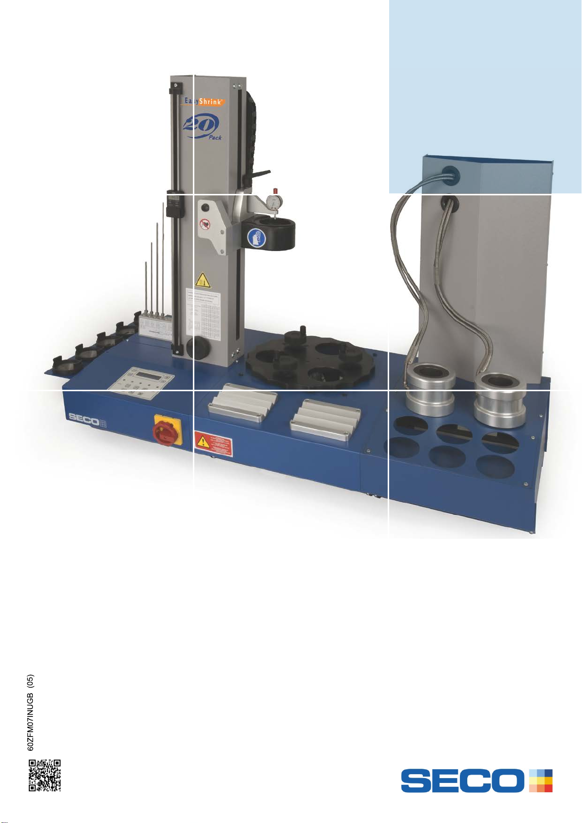
1. GENERAL OVERVIEW
HEATING MODULE
WITH HEIGHT SETTING
REFRIGERATED WATER
COOLING BELLS UNIT
THREE-STATION ROTARY
SUPPORT BOX WITH HEIGHT
SETTINGS
Always wear protective gloves while handling Shrinkfit
holders, tools, accessories and spare parts.
Individuals who carry medical implants are banned from using
or working with this device. The carriers of a pacemaker must
refer to the specific note of the pacemaker established on the
basis of : NF EN 60601-1-2 (september 2007).
Electrical hazard when dismountingparts of modules.
Separated power supply of the support module, is
not cut off by the main switch.
8
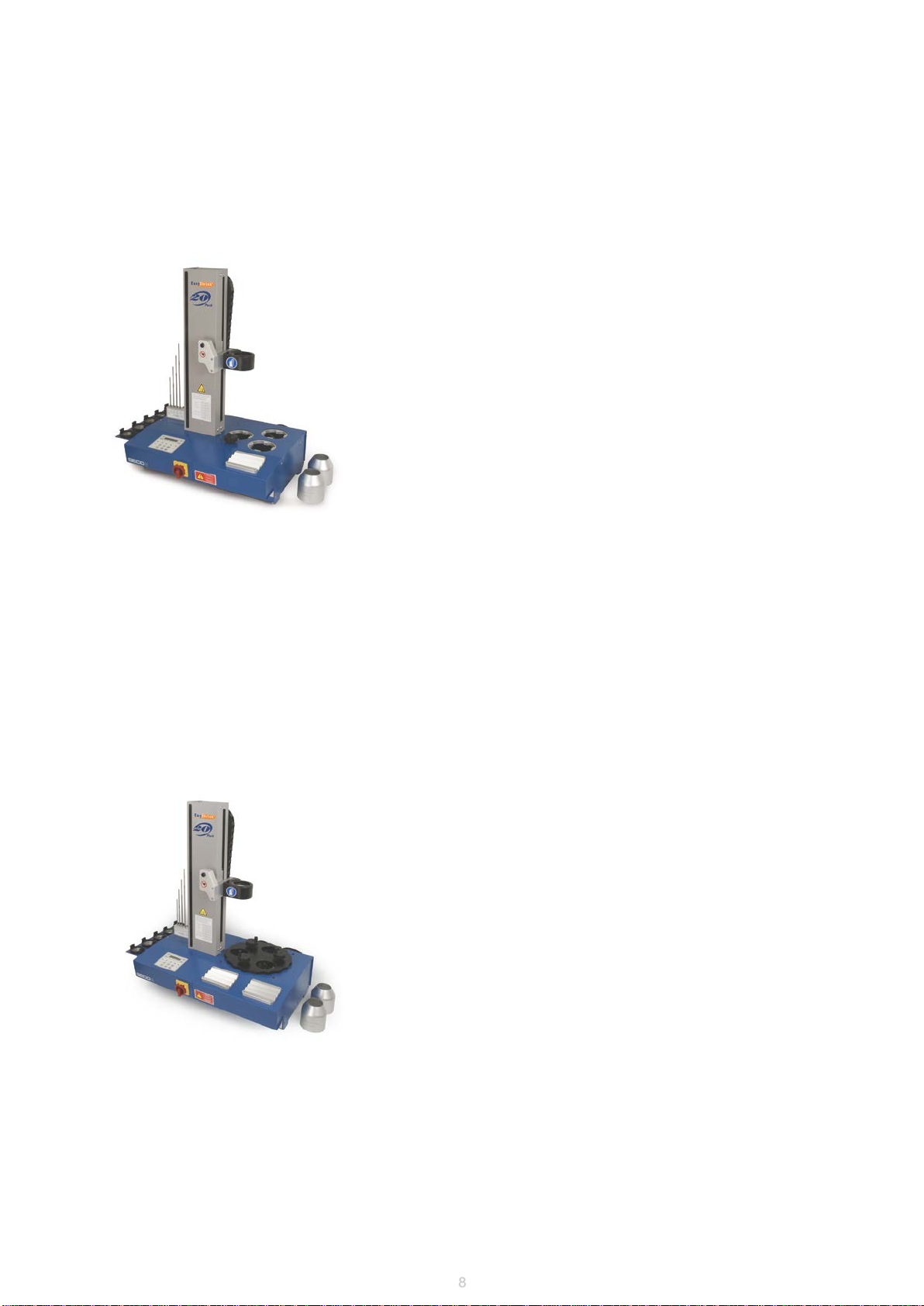
1.1 PACKS EASYSRINK® 20 DESCRIPTION
1.1.1 Pack Easyshrink®20 N°1, ZFM07IN10
A complete set with induction heating, 1 operating stationwith shrink
depth setting and 2 cooling stations.
Operatingstation holdthe finnedsupportswith toolholderduring the heating
cycles.
Cooling processby ventilatorstreamed air.
Shrink grip and shrinkrelease capacity Ø 3 to 32 mm for carbide, heavy
metal, steel and HSS tool shanks.
Automaticor programming heating modes for shrinkgrip and shrink release
heatingcycles.
Control drivesthe other modules.
1.1.2 Pack Easyshrink®20 N°2, ZFM07IN20
A complete set with induction heating, rotary plate of 3 operating + shrink
depth setting + cooling stations.
Operatingstations hold the finned supportswith toolholderduring the heating
and cooling cycles.
All three stationsare operating, shrink depth setting and cooling stations:
while one stationis used to shrink-gripor shrink-release the two others can be
in cooling position.Each station is equippedwith a LED indicator which
switches on automatically when table is rotatedinto a cooling position.
The rotary plate preventsthe user having any contactwith hot holders.
Cooling processby ventilatorstreamed air.
Shrink grip and shrinkrelease capacity Ø 3 to 32 mm for carbide, heavy metal,
steel and HSS tool shanks.
Automaticor programming heatingmodes for shrink grip and shrinkrelease
heatingcycles.
Control drivesthe other modules.

9
1.1.3 Pack Easyshrink®20 N°3, ZFM07IN30
A complete set with induction heating, rotary plate of 3 operating + shrink
depth setting + cooling stations, height measuring and a refrigerated
cooling bells water cooler.
Operatingstations hold the finned supportswith toolholderduring the heating
and cooling cycles.
All three stationsare operating, shrink depth setting and cooling stations:
while one stationis used to shrink-gripor shrink-release the two others can
be in cooling position.Each station is equippedwith a LED indicator which
switches on automatically when table is rotatedinto a cooling position.
The rotary plate preventsthe user having any contactwith hot holders.
Shrink grip and shrinkrelease capacity Ø 3 to 32 mm for carbide, heavy
metal, steel and HSS tool shanks.
Automaticor programming heating modes for shrinkgrip and shrink release
heatingcycles.
All Packs are delivered with:
Apair of gloves.
Five standard (fullset) heat focusingstoppers for 3 to 32 mm, their storage rack and adapter.
Aset of 4 standard stop rodsin a rack.
Operatinginstructions.
Additonal in Packs N°1 and 2:
Two cooling cones
1.2 PACKS DELIVERY CONTENT
The height measuring fittings include:
- A fine adjustmentof the sliding support usinga height adjustmentsetting wheel.
- A digital rule to controlthe sliding support /comparatorposition (0,01mm display).
- A comparator (0,01 mm) fi xed onto the inductorsliding support.
Achieves shorter coolingtimes with the refrigerated coolingbells water cooler.
The cooler includes a refrigerationunit and a support unit for coolingbells and contact bushes.Two aluminium bells
are cooled by refrigeratedwater and placedover contact bushesonto the front end of the holder, coolingtime approx.
1 minute. There are 2 storingrests for the bells and 6 storage
locations for contactbushes.
Control drivesthe other modules.
Note: a refrigerated cooling bells water cooleris part of Pack Easyshrink®20 N°3. It can be added to the the
Packs Easyshrink® 20 N° 1 and 2.

10
1.3 Dimensions
Heatingmodule
Three-stationrotary supportbox
Refrigeratedwater cooling bells unit
Three-stationsupport box (1 operatingand 2 cooling
stations)

11
05R5600__
Stop screw setting adapterwith hexagonal back-end
05RS5800__
Tool supporting sleeve for stop rod
ZFAR02C__ _
Finned cooling tube ZFAR10D__ _
Contact bush for cooling bells ZFAR03C
Air cooling cone
ZFCE25__
Split heat focusing stopper (pairs ofhalf plates ZFCE25_ _
and ring ZFCM08IN000)
ZFAT08C__
Standard heatfocusing stopper
ZFAD05__ _
Finnedsupport ZFAR07H_ _ _
Supportring
ZFS07IN043
Stop rods set, standard, threadfitting ZFS07IN018
Stop rods set, thin, thread fitting
STOP ROD ACCESSORIES
FLANGE ACCESSORIESCOOLING ACCESSORIESOTHER ACCESSORIES
Z847031
Depth comparatorfor stop
rod setting
ZFS07IN282
Depthrulers for Shrinkfit depth setting,for
Shrinkfit holders Ø 3 to 5 mm
ZFS07IN254
Depthrulers for Shrinkfit depth setting,for
Shrinkfit holders Ø 6 to 32 mm

12
1.4 Stop rod accessories
1.4.1 Stop rods set, standard, thread fitting (Part No. ZFS07IN043)
1.4.2 Stop rods set, thin, thread fitting (Part No. ZFS07IN018)
4 stop rods with 2,5 mm front end, coveringa shrink depth capacity0 to 240 mm: 0-60
/ 60-120 / 120-180/ 180-240 mm.
Thin stop rods are for Shrinkfit holders Ø 3 à 5 mm.
When stop rod is used in combinationwith a digital rule with display,it allows alsothe
tool lenght setting.
4 stop rods with 5 mm front end, coveringa shrink depth capacity0 to 240 mm: 0-60 /
60-120/ 120-180 / 180-240mm.
Allows the tool shrinkingdepth setting.
When stop rod is used in combinationwith a digital rule with display,it allows also the
tool lenght setting.
1.4.3 Depth comparator for stop rod setting (Part No. Z847031)
User friendly measuringaccessoryto set stop rod’s position for reliableShrinkfit depth
with EasyShrink20. The distance between stop rod’s front and holder’sfront face is
directly readable on the comparator.
See Operating instructions 60Z847031U01-FR/GB/DEdelivered with the depth
comparator.
1.4.4 Depth rulers for Shrinkfit depth setting
A depth ruler is an economic alternative to the depth comparator,enabling easy
setting of the stoprods on Packs Easyshrink® 20 accordingto a required
Shrinkfit depth.The distance betweenstop rod’s front and holder’s face is
directly readable on the ruler.
Depth ruler size 1 (∅2,5 mm) for Shrinkfitholders dia. 3 to 5 mm, depth capacity
10 to 35 mm: Part No. ZFCM07IN282.
Depth ruler size 2 (∅5 mm) for Shrinkfi t holdersdia. 6 to 32 mm, depth capacity
20 to 75 mm: Part No.ZFCM07IN254.
Depth ruler size 1
Depth ruler size 2
13
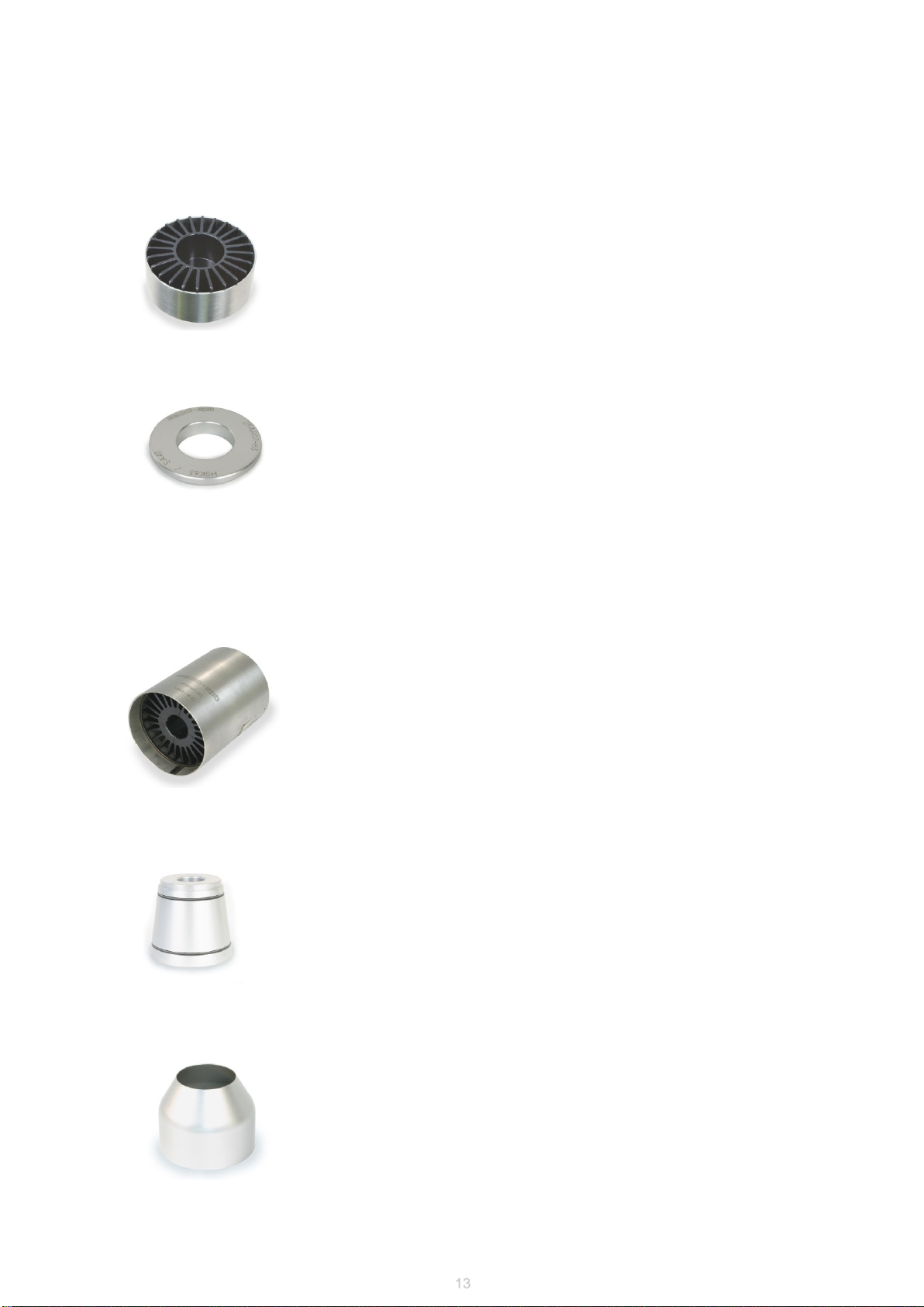
1.6 COOLING ACCESORIES
1.6.1 Finned cooling tube
Available for all types of shrinkfit holdersand diameters (5800-5801-5603-5600).
Required to receive the air stream comingthrough the fins.
Fins are in contact with the holder front end and offer a great contact surfacefor fast heat
dispersal.
1.6.2 Contact bush for cooling bells
Available for all types of shrinkfit holdersand diameters (5800-5801-5603-5600).
Required to extract heat from the holderfront end towards the liquid coolingbell.
1.6.3 Air cooling cone
Direct the air stream againstthe holder front end for cooling.
1.5 Flange accessories
1.5.1 Finned supports
Available for all types of toolholders(SA30 to SA50, HSK25 to HSK100, Capto sizeC3 to
C8).
Required to provide positioningof the toolholder ontothe support module.
1.5.2 Support ring
Available for all types of toolholders(SA30 to SA50, HSK25 to HSK100, Capto sizeC3 to
C8).
Only suitable for the cooling stations,allows a direct holder positioning.

14
1.7 Other accessories
1.7.2 Stop screw setting adapter with hexagonal back-end
Availablefor all tool shank diameters(Ø 6 to 32 mm).
Allows to preset the tool length with the use of a stop screw which can be fitted into
type 5603 Shrinkfitholders.
For use instructions,see §8.10.
1.7.1 Tool supporting sleeve for stop rod
Availablefor all tool shank diameters(Ø 3 to 32 mm).
Useful for locatingthe cutter back end (in contact) onto the stop rod front end.
For use instructions,see §8.9.
1.7.3 Heat focusing stopper
For positioning of the inductor housing
Standardheatfocusing
stopper
Pairs of split heat focusing
stopper andring
Capacity
Ø mm Standard heat
focusing stopper Pairs of split heat
focusing stopper
3 –6 ZFAT08C01 ZFCE2521
8 – 14 ZFAT08C02 ZFCE2522
16 – 18 ZFAT08C03 ZFCE2523
20 - 25 ZFAT08C04 ZFCE2524
32 ZFAT08C05 ZFCE2525
Locking ring / ZFCM08IN000

15
2. PACKS INSTALLATION AND USE
2.1 Shrinking principle
The Shrinkfit holder’sinside diameteris designed to be slightly smallerthan the shank diameter of the cuttingtool. When
placed into the inductionheating system,the inside bore is heated and expands. The tool shank can then be slippedeasily
into the holder. As the holdercools down, the resultingthermal contractionexerts a tremendous,uniform pressure around
the entire surfaceof the tool shank.
Induction
Induction heating allows clampingtools in a few seconds. The 10 KW coil
offers high performance.The energy is sprayed very rapidelyand remains
concentratedon the clamping area. Therefore thereis less energy remaining
in the holder, coolingtime is decreased. That allows to unshrinkingHSS tools
with same thermalexpansion coefficientsas the steel used for the holders.
16
The device you receivedhas been controlledand tested in our plant acc. to ISO9001specifications
If the equipmentis being stored or transportedunder unacceptableconditions the equipmentmay be permanentlydamaged. In
these casethe manufacturer will excludeall warranty claimsand obligations.
Unpackinghas to be made carefully to avoid all damages.
2.2 Taking delivery
2.3. Localization of the module
The EASYSHRINK Pack is a table device,to be localized in a dry and clean working place,on a stable and rigid surface.
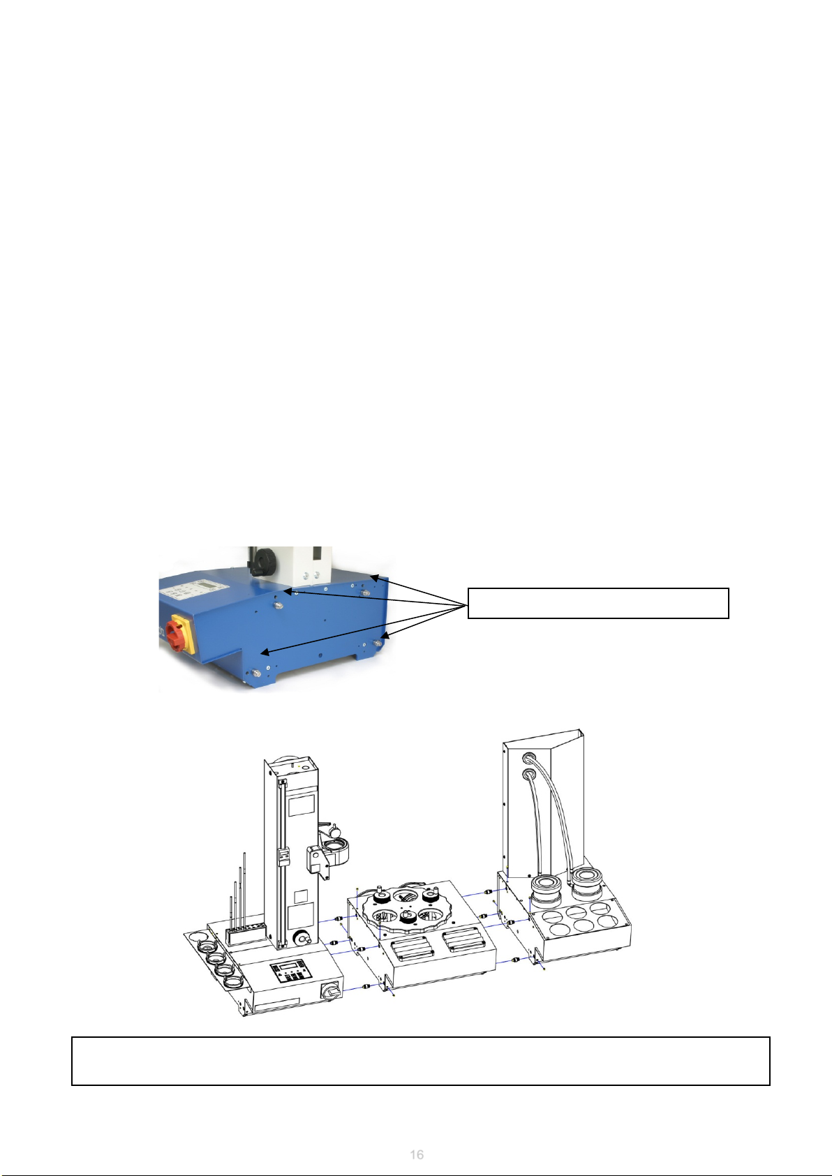
2.4. Packs mounting
Each supportmodule is fixed with 4 pins side by side and are held by 4 pin point screwsreachable at the location of the
pins.
Screw the 4 pins in the side plate
•Example : mounting of Pack Easyshrink®20 N°3, ZFM07IN30
Mounting of 3 individual modules like shown hereunder.
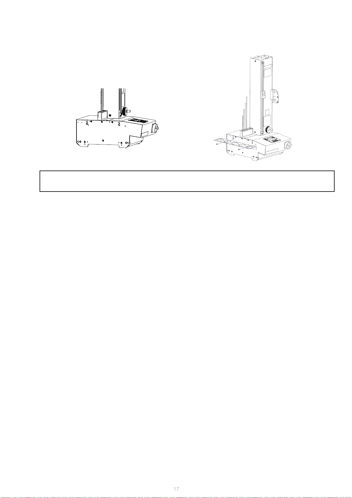
17
•Mounting of support corner plate for heat focusing stopper
Support corner plate for heat focusingstopper is fixed on the heatingmodule left side plate with 2 screws supplied with
the support.

18
•Inductor housing setting in relation with the support modules
Install a heat focusingstopper onto the inductorhousing.
Using a toolholder,set on the finned support, underthe inductor, check the
alignment of the inductor in comparisonto the finned support.
Favourable case: the focusing stopper is
properly aligned.
The inductor is ready to be used.
Unfavourable case: the focusing stopper is out
of alignment, proceed to the following set of
instruction (§B).
A. Procedure to check the alignment of the inductor
- Unscrew the two lower screws of the inductor.
- Unscrew the two upper screws of the inductor.
If the heat focusingstopper is out of alignment (cf. A above):
You have now accessto the upper screws of the inductor.
- unscrew the two screws of the comparator,
- remove the comparator.
B. Centring of the inductor

19
2.6 Starting
Switch on main interruptor of the heatingmodule.
On the display the yellowLED will go on.
Displayshows : POWEROFF.
2.5 Connections
- Once the inductoris unlocked, center it (for example,using a conical toolholderset
on the finned support);then rescrew the four screws.
- Set up the comparatorback.
All Packs:
AC 3x400V(+/-10%)+ PE/ 16 A/ 50-60Hz/Differential breaker 30 mA. 3 meter
cable is supplied.
AC 1x230V+ PE/5A/50-60Hz,cable with a DE/FR electricalplug is supplied
with support box.For connections see paragraph 3.2 and 4.2
Additional for Pack N°3 :
+ AC 1x230V + PE/5A/50-60Hz, cablewith a DE/FR electrical plugis supplied
with refrigeratedwater cooling. For connectionssee paragraph5.3
Air 3 to 6 bar/ pipe internal Ø 7 mm required (for heating system).
Type C circuitbreaker.
Remark : Transformerfor USA or Canadianvoltages is availableas an optional
accessory.

20
Programming
button
Heating
cycle
Driving of
support
modules
On / Off
Display
Enter
Scrolling
keys
LED 1 LED 2 LED 3 LED 4 LED 5
2.7 Control panel and display presentation
Table of contents
Other Seco Industrial Equipment manuals


