Seco EASYSHRINK 15 User manual
1
60ZFM08INUGB (07)
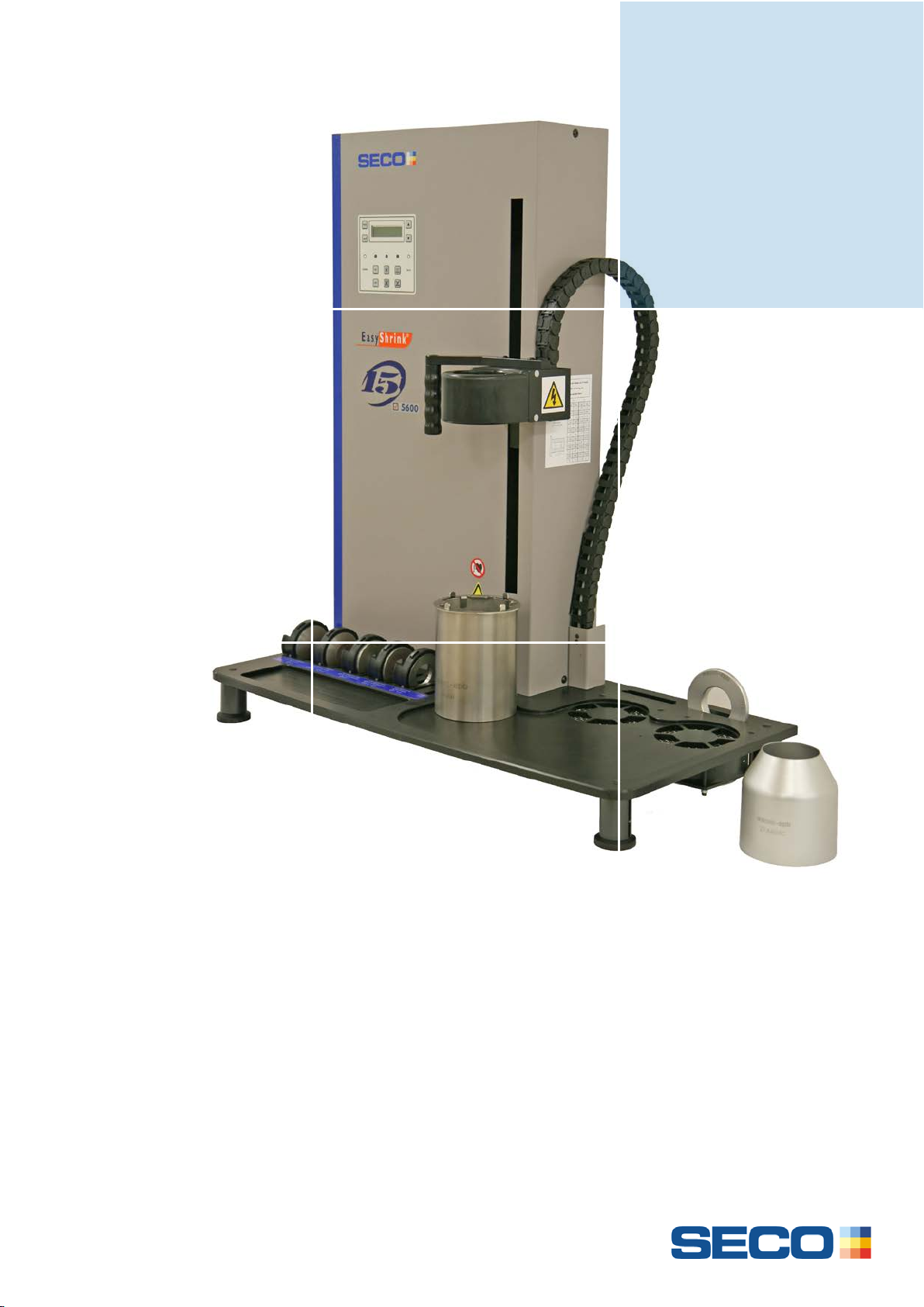
EASYSHRINK®15
OPERATING INSTRUCTIONS
SHRINKFIT DEVICES

2
Dear Customer,
We thank you for having purchased an Easyshrink®15 shrinking device.
This inductionshrinking device will offer you a lot of advantages:
- automatic* or programming heating cycles
- optimised cycles to shrink-grip and shrink-release tools
- localized and homogeneous heating of the clamping area
- minimal energy consumption
fast cooling of the tool and the toolholder
- clamping of carbide, HSS and steel toolshanks
These operating instructions will give you all necessary information to use this devicein the best way.
Should you need further clarifications, our sales-team stays at your full disposal.
Your Partner,
Seco Tools AB.
*Designed for Seco‘s toolholders, to be validated for other brands.
Provisions of warranty
If your product proves to be defective, although it has been used properly (in accordance with this written Operating
instructions manual), during a period of 24 months from the date of invoicing, this product will be repaired or replaced (at
Seco’s option), freeof charge.
This warranty covers the material defects. Any defect that occurs due to mishandling that is not mentioned in this Operating
instructions manual, or due to an improper maintenance, etc. is not covered. Seco’s sole liability is limited to repairing or
replacing the product. Any liability for indirect or consequential loss or damage of any kind incurred or suffered by the
customer due to a defect of the product is excluded.

3
TABLE OF CONTENT
DELIVERY CONTENT .............................................................................................................................................4
1. INTRODUCTION ............................................................................................................................................5
1.1. SHRINKING PRINCIPLE .............................................................................................................................5
1.2. SHRINKING WITH INDUCTION ....................................................................................................................5
2. RECEPTION OF YOUR DEVICE ...................................................................................................................6
2.1. TAKING DELIVERY....................................................................................................................................6
2.2. ACCESSORIES,SPARE PARTS AND OPTIONS .............................................................................................6
2.2.1. Universal sliding support...................................................................................................................6
2.2.2. Support ring......................................................................................................................................6
2.2.3. Air cooling cone ................................................................................................................................6
2.2.4. Heat focusing stopper.......................................................................................................................6
2.2.5. Depth comparator.............................................................................................................................6
2.2.6. Depth rulers for Shrinkfit depth setting..............................................................................................7
2.2.7. Protecting gloves..............................................................................................................................7
2.2.8. Complementary cooling devices.......................................................................................................7
2.3. DIMENSIONS (WHEN MOUNTED) ...............................................................................................................7
2.4. LOCALISATION OF THE DEVICE .................................................................................................................8
2.5. MOUNTING..............................................................................................................................................8
2.6. POWER SUPPLY ....................................................................................................................................10
3. EASYSHRINK®15 DEVICE: GENERAL DESCRIPTION.............................................................................11
3.1. OVERVIEW............................................................................................................................................11
3.2. KEYPAD AND DISPLAY PRESENTATION ....................................................................................................12
4. USING THE DEVICE....................................................................................................................................13
4.1. PUTTING THE DEVICE UNDER TENSION ...................................................................................................13
4.2.TURNING ON THE DEVICE.......................................................................................................................13
4.3. SHRINKING PROCEDURE ........................................................................................................................13
4.3.1. Description of the different heating modes .....................................................................................13
4.3.2. Selection of the heating mode ........................................................................................................14
4.3.3. Using programmable modes PRG1 and PRG2 ..............................................................................14
4.3.4. Preparation before shrinking cycle..................................................................................................16
4.3.5. Minimal and maximal shrinkfit assembly’s height ...........................................................................16
4.3.6. Shrinking depths to be respected ...................................................................................................17
4.4. SHRINKING A TOOL INTO A TOOLHOLDER ................................................................................................17
4.5. SHRINK RELEASE PROCEDURE ...............................................................................................................18
4.6. SHRINKING OF TOOLS WITH LARGER FRONT THAN SHANK ........................................................................19
4.6.1. Clearance between tool head and toolholder front face..................................................................19
4.6.2. Shrinking procedure for tools with larger front than shank..............................................................19
4.6.3. Shrink-releasing procedure for tools with larger front than shank...................................................20
5. COOLING.....................................................................................................................................................21
5.1.1. Piloting the cooling fans..................................................................................................................21
5.1.2. Cooling time modification................................................................................................................21
6. SAFETY PRECAUTIONS.............................................................................................................................22
7. RECOMMENDATIONS FOR USE AND MAINTENANCE ...........................................................................22
8. SAFETY FUNCTIONS OF THE EASYSHRINK®15.....................................................................................22
9. APPENDICES ..............................................................................................................................................22
9.1. TECHNICAL FEATURES...........................................................................................................................22
9.2. ELECTRICAL SKETCH .............................................................................................................................23
9.3. CE COMPLIANCE CERTIFICATE ...............................................................................................................24
4
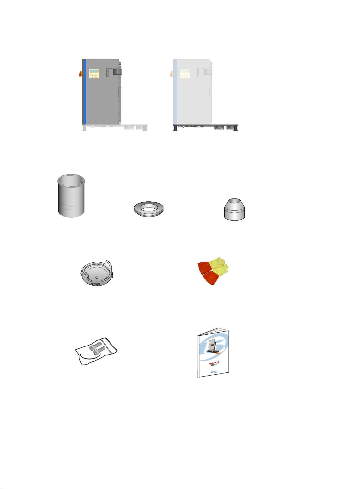
DELIVERY CONTENT
Heating column
(1 piece)
Main plate
(1 piece)
User instructions
(1 piece)
Set of 2 fixing screws and 1
cable tie
(1 piece)
Standard heat
focusing stopper
(complete set of 5 pieces)
Universal sliding
support
(1 piece)
Support ring
(1 piece)
Heat protective gloves
(1 pair)
Cooling cone
(1 piece)

5
1. INTRODUCTION
1.1. Shrinking principle
The Shrinkfit holder’s inside diameter is designed to be slightly smaller thanthe shank diameter of thecutting tool (step 0).
Using an heating system, the toolholder’s inside bore of the Shrinkfit holder is heated and expands. The tool shank can then be
slipped easily into it (step 1).
As the holder cools down, theresulting thermal contraction exerts a tremendous, uniform pressure around the entire surface of the
tool shank (step 2).
1.2. Shrinking with induction
Induction heating allows clamping tools in a few seconds. The coil offers high performance as the
energy is sprayed very rapidly and remains concentrated onthe clamping area. Therefore, there is
less energy remaining in the holder and the cooling time is decreased.
As a result, HSS tools can be shrinked and unshrinked with same thermal expansion coefficients
as the steel used for the holders.
d
1(holder)
d
1(tool)
d
1(holder)
d
1(holder)
d
1(tool)
Step 0
d1(holder) < d1(tool)
Step 1: heating
d1(holder) > d1(tool)
Step 2
d1(holder) = d1(tool)
(with constraints)
Step 2
d1(holder) = d1(tool)
(with constraints)
Step 2: cooling
d1(holder) = d1(tool)
(with constraints)
d
1(tool)
6
2. RECEPTION OF YOUR DEVICE
2.1. Taking delivery
The device you have received has been controlled andtested in ourplant according to ISO9001 specifications.
If the equipment has been stored or transported under unacceptable conditions, the equipment may be permanently damaged. In
this case the manufacturer willexclude all warranty claims andobligations.
2.2. Accessories, spare parts and options
This paragraph shows the most common accessories for this device. Please refer to the latest Machining Navigator ‘Tooling
Systems’ or latest Update for further information.
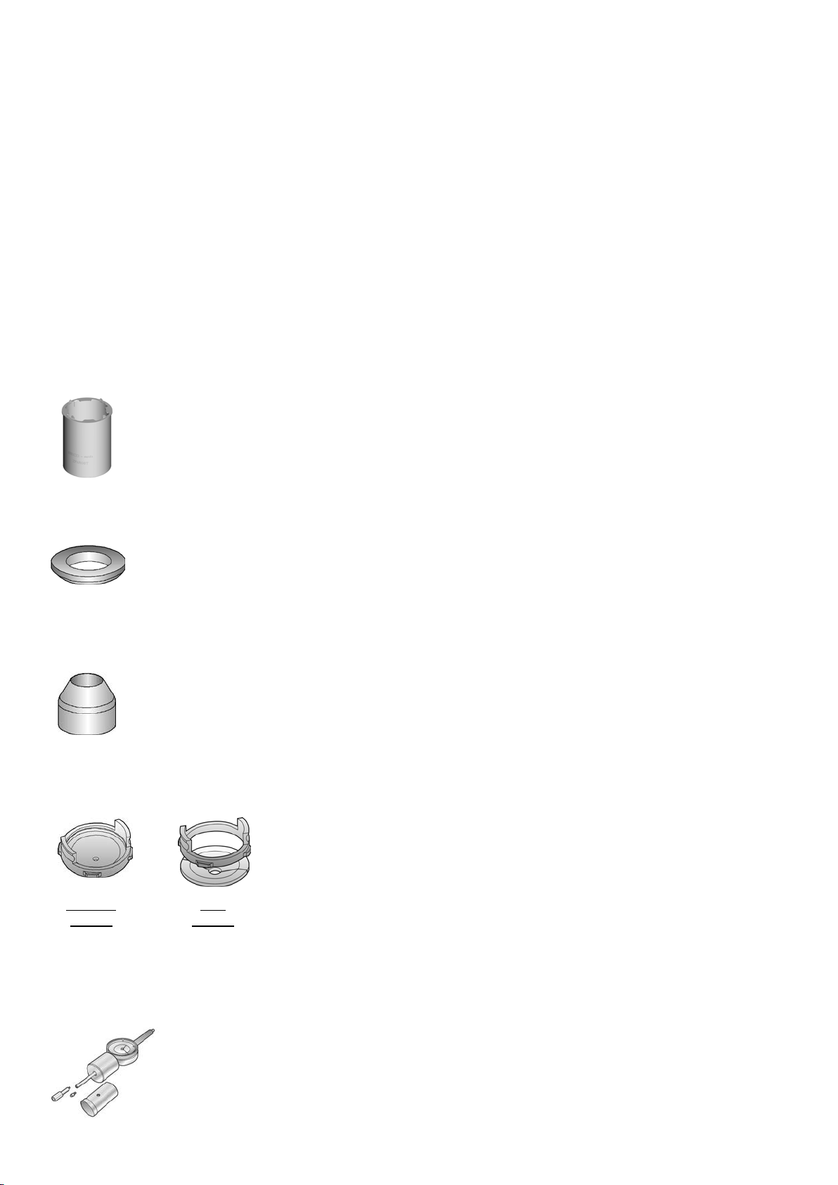
2.2.1. Universal sliding support
Designed for easy and safe displacement of the toolhoder from the shrinking slot to the cooling slots of the device.
Part N° ZFAR08T
2.2.2. Support ring
Once set on the universal sliding support, the support ring allows a direct holder positioning. Available for all types
of toolholders (SA30 to SA50,HSK25 to HSK100, Seco-Capto C3 to C8). Part N° ZFAR07xx
2.2.3. Air cooling cone
Once set on the universal sliding support, the air cooling cone focuses the air stream against the holder front end for
cooling. Part N° ZFAR03C
2.2.4. Heat focusing stopper
For positioning of the inductor housing.
Part N° Standard stoppers: ZFAT08Cxx
Part N° Split heat focusing stoppers: ZFCE252x
Part N° Locking ring for split heat focusing stoppers: ZFCM08IN000
2.2.5. Depth comparator
User friendly measuring accessory to set the position of the stop end screw (for DIN type holders), for
reliable Shrinkfit depth. The distance between the stop endscrew’s front and the holder’s front face is directly
readable on the comparator.
Part N° Z847031
Split
stopper
Standard
stopper

7
2.2.6. Depth rulers for Shrinkfit depth setting
A depth ruler is an economic alternative to the depth comparator, enabling easy setting of the stop rods
on Packs Easyshrink®20 according to a required Shrinkfit depth. The distance between stop rod’s front
and holder’s face is directly readable on the ruler.
Depth ruler size 1 (∅2,5 mm) for Shrinkfit holders dia. 3 to 5 mm, depth capacity 10 to 35 mm:
Part No. ZFCM07IN282.
Depth ruler size 2 (∅5 mm) for Shrinkfi t holders dia. 6 to 32 mm, depth capacity 20 to 75 mm:
Part No.ZFCM07IN254.
2.2.7. Protecting gloves
Direct skin contact with hot toolholders will cause severe injuries. The use of appropriate protecting gloves is
mandatory to warranty the security of youroperators. Conform to norm EN407 and EN388. Part N° ZFAG01
2.2.8. Complementary cooling devices
Complementary water cooling devices are available for faster cooling of the toolholders. Please refer to the Machining Navigator
‘Tooling Systems’.
2.3. Dimensions (when mounted)
840
880
400
50KG
8
Centering
pins
2.4. Localisation of the device
The Easyshrink®device is a table device, to be localized in a dry and clean working place, on a stable and rigid surface.
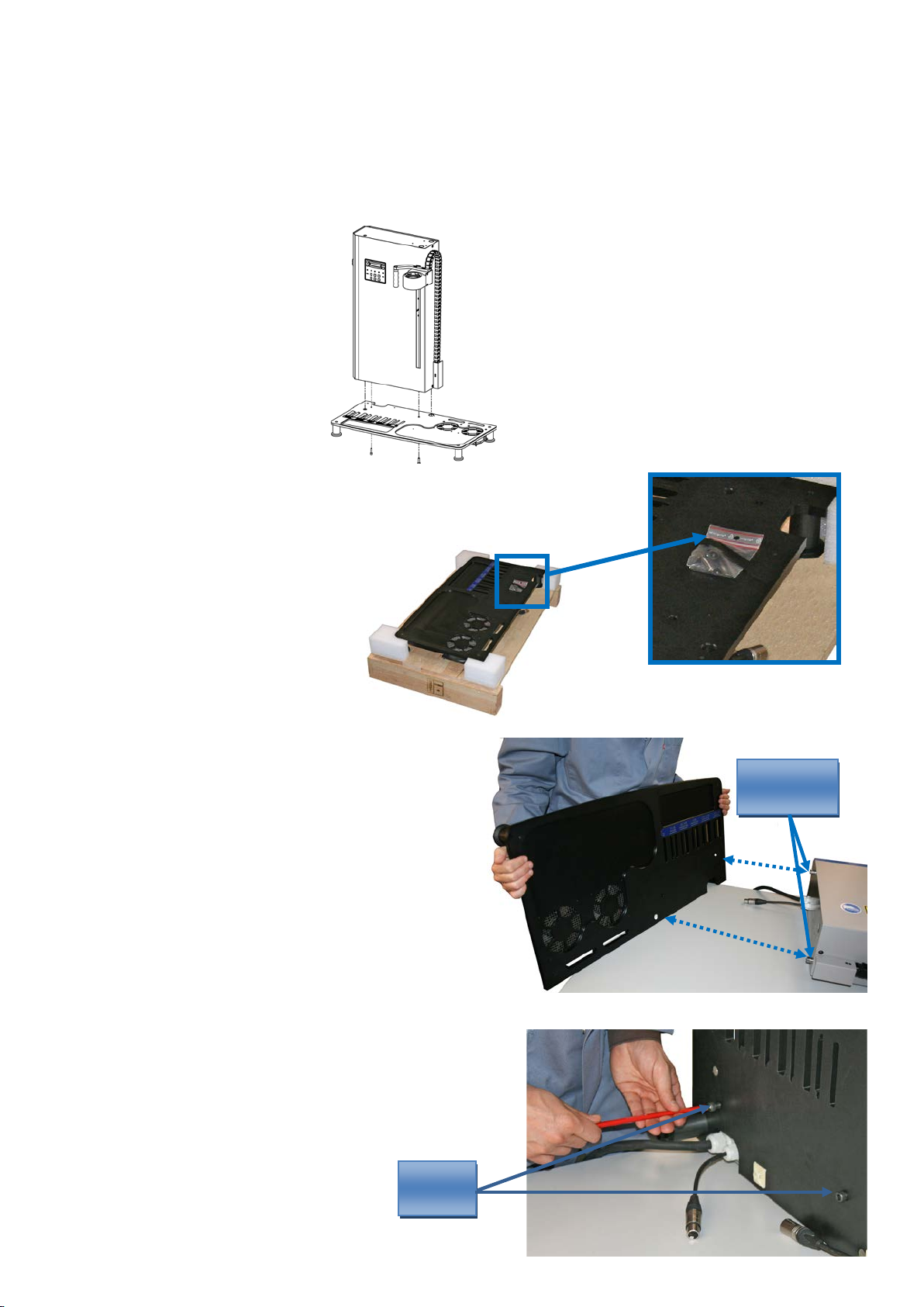
2.5. Mounting
A bag with two fixing screws and one cable tie is delivered on the main plate of the device.
Make sure you save theseparts that are required tomount the device.
1) Lay the column on a table.
2) Present the main plate against the column and fit the centering
pins in the slots of the main plate.
3) Fix the column on the main plate, using the two fixing screws.
Fixing
screws
9
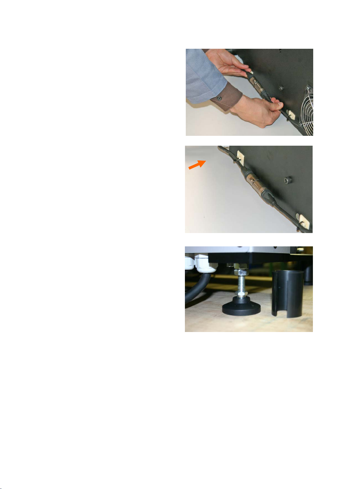
4) Plug the fans’ powersupply wire in.
5) Use the provided cable tie to fix the fans’ power supply wire on
the main plate.
6) The main plate’s feet (on the back, left corner) can be set in
height to warranty the stability of the device.
‘clic’

10
2.6. Power supply
The Easyshrink®device is meant to be supplied with power according to these
specifications:
AC 3x400V + PE/ 16A/ 50-60 Hz.
A 3,5 meter cable is supplied.
Please install the appropriate male and female plugs to connect the device to your electrical network and make sure the proper
tension is delivered between each pin.
Note: A transformer for USA or Canadian voltages is available
as an optional accessory. Please contact your Seco
representative.
Name of
the pin
Designation
of the pin
Colour of the
wire
L1 Phase L1 brown
L2 Phase L2 black or grey
L3 Phase L3 black
PE Ground green & yellow
Tension in V
230
230
230
400
400
400
L1 → L2
L1 → L3
L2 → L3
Measure between the
pins
PE → L1
PE → L2
PE → L3

11
3. EASYSHRINK®15 DEVICE: GENERAL DESCRIPTION
3.1. Overview
Main swith
Inductor housing
Cooling stations
Storage rack for tools
Keypad and
display
Main plate
Storage rack for
support rings
Universal sliding
support
Storage rack for heat
focusing main plates
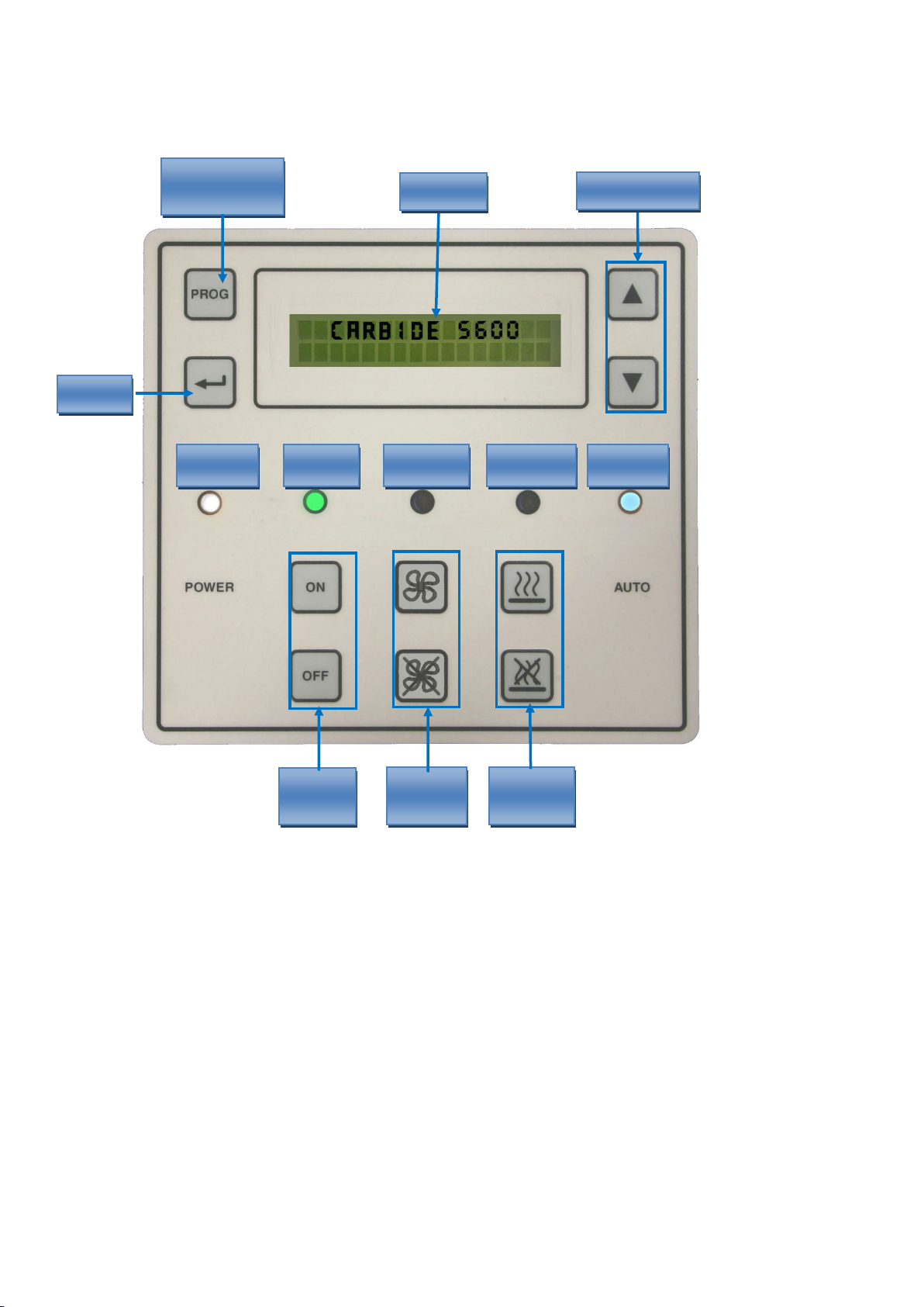
12
Programming
button
Heating
cycle
Fans
On/Off
Device
On/Off
Enter
Main switch
on/off
Device
on/off
Cooling fans
on/off
Heating cycle
on/off
‘auto’ mode
on/off
Display
3.2. Keypad and display presentation
Scrolling keys
13
4. USING THE DEVICE
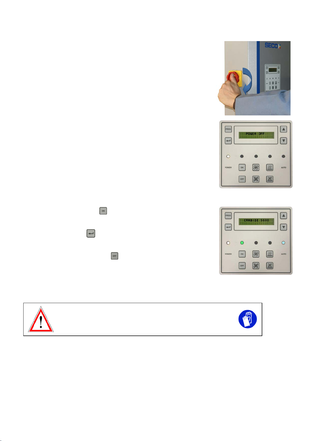
4.1. Putting the device under tension
Switch on the main interrupter of the device.
On the keypad, the white LED will go on.
Display shows: POWER OFF.
4.2. Turning on the device
Switch on the module by pressing key .
Select the required mode on the control panel according to the Shrinkfit holder front end
type (see § 4.3.) and press key
Device is ready for a shrink grip or release heatingcycle.
Switch off the control panel by pressing key .
4.3. Shrinking procedure
Wearing supplied protective gloves is imperative while handling the device
and Shrinkfit holders/tools.
4.3.1. Description of the different heating modes
AUTOMATIC MODES: User selects the required automatic mode on the control panel, no need to select the diameter.
CARBIDE 5800: optimised shrink grip &release of carbide and heavy metal tools in type 5800 holders
CARBIDE 5801: optimised shrink grip &release of carbide and heavy metal tools in type 5801 holders
CARBIDE 5603: optimised shrink grip &release of carbide and heavy metal tools in type 5603/5803 holders
CARBIDE 5600: optimised shrink grip &release of carbide and heavy metal tools in type 5600 holders
STEEL 5600: shrink grip & release of HSS and steel tools in type 5600 holders
STEEL 5800-5801-5603: shrink grip & release of HSSand steel tools in type 5800, 5801,5603/5803holders.
14
PROGRAMMABLE MODES:User programms the suitable cycle, inone of the 50 files of modes PRG1 and PRG2, using the
control panel.
Mode PRG1: possibility to programm up to 25 customised heating cycles
Mode PRG2: possibility to programm up to 25 customisedheating cycles
Seco Shrinkfit holders Code key
E 9304 5603 10 120
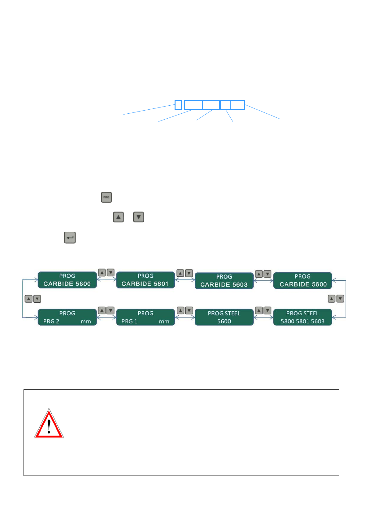
4.3.2. Selection of the heating mode
• Selection of the required mode:
On the control panel, press key
Select the required mode using key or (see picture below)
Then press key to confirm your selection
Device is ready fora shrink grip or release heating cycle.
4.3.3. Using programmable modes PRG1 and PRG2
•Heating time modification
In order to prevent misuse of these modes, the modification of the heating times is secured and
an access code is required.
By security measure, heating times of PRG 1 and PRG 2 are preset to 0 second.
The access code and the procedure to modify the heating times are given on request and after
complete information about the risks.
Any change of the preset time must be made carefully, toolholder overheating makes it unusable.
In case of modification without our agreement, Seco Tools AB. cannot be held as responsible for
any damage.
Front end type
Tool fitting Ø size
E= Monobloc holder
Gauge length
Back end taper type

15
• Selection of the unit mm, inch, or mm and inch with mode PRG 1 or PRG 2:
On the control panel, select mode PRG 1 or PRG 2 (see § above)
Press two times key
Choose between mm, inch, or mm and inch using key or
Press two times key to confirm and come back to working mode.
•Diameter scrolling according to the selected unit.
Note: Diameters X1, X2, X1’’and X2’’ are used for special diameter of tools, they can be programmed for specific applications.
Scrolling in mm
Ø(mm) Ø 3 Ø 4 Ø 5 Ø 6 Ø 8 Ø 10 Ø 12 Ø 14 Ø 16 Ø 18 Ø 20 Ø 25 Ø 32 Ø X 1 Ø X 2
Scrolling in inch
Ø (inch) Ø 1/4" Ø 3/8" Ø 1/2" Ø 5/8" Ø 3/4" Ø 7/8" Ø 1" Ø 1"1/4 Ø X 1" Ø X 2"
Scrolling in mm and inch
Ø
(mm +
inch)
Ø 3 Ø 4 Ø 5 Ø 6 Ø 1/4" Ø 8 Ø 3/8" Ø 10 Ø 12 Ø 1/2" Ø 14 Ø 16 Ø 5/8" Ø 18 Ø 3/4"
Ø 20 Ø 7/8" Ø 25 Ø 1" Ø 32 Ø 1"1/4 Ø X 1 Ø X 2 Ø X 1" Ø X 2"

16
4.3.4. Preparation before shrinking cycle
1) Position theuniversal sliding support on the heating station.
2) Install on it the support ring that corresponds to the Shrinkfit toolholder’s taper.
Please refer to the latest Machining Navigator ‘Tooling Systems’ or to the
Machining Navigator ‘Update’ to select the appropriate support ring.
3) Choose the adapted heat focusing stopper that corresponds to the tool shank
diameter.
Note: 5 heat focusing stoppers are supplied with each device, capacities: Ø 3-6,
Ø 8-14, Ø 16-18, Ø 20-25, Ø 32 mm.
4) Install it into the location diameter in the inductor housing. Turn it around to
lock it on the inductor housing.
4.3.5. Minimal and maximal shrinkfit assembly’s height
Minimum height between
inductor and flange location
160 mm
Maximum height between
inductor and main plate
620 mm
Maximum ‘A length’ of the
assembly ‘holder+tool’
460 mm
Universal
sliding
support
Support ring
620
460
160
17
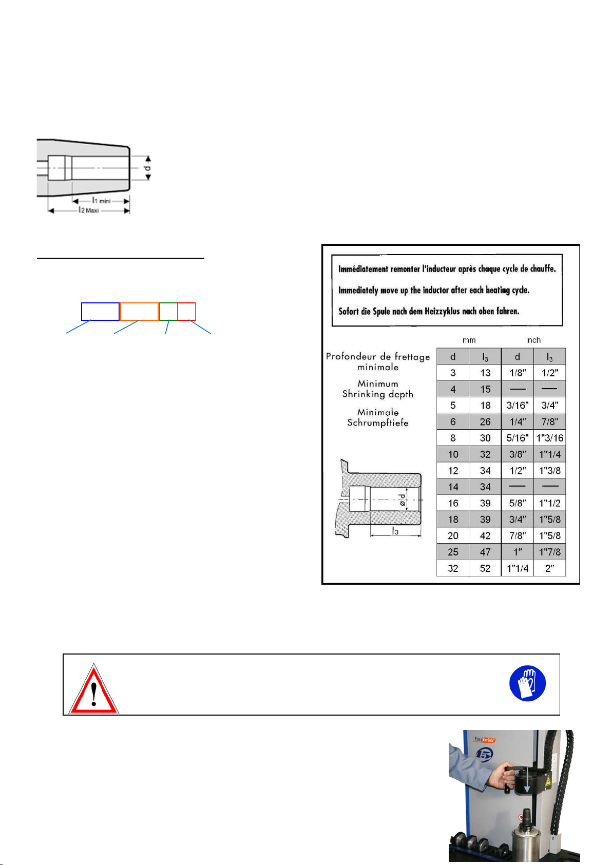
4.3.6. Shrinking depths to be respected
In order to guarantee torque transmission and to increase service life of the tool, recommended
values for shrinking depth must be respected.
Find the minimum shrinking depth from the chart below (also on the device).
Example for a Seco toolholder type 5603
The diameter d and the jauge length are indicated on the
toolholder:
The shrinking depth (depending on the position of the stop end
screw) must be set minimum to l3.
In this case, the chart indicates l3=39 mm.
4.4. Shrinking a tool into a toolholder
Wearing supplied protective gloves is imperative while handling the device and
Shrinkfit holders/tools.
Note: recommended cylindrical tool shank tolerance is h5 or h6 (maximum h5 for Ø 3 to 5 mm,
maximum h6 forØ 6 to 32 mm).
1) Move the inductor housing downwards, until the heat focusingstopper entersin contactwith the
top of the toolholder.
E9343 5603 1670
Front end
type
Tool
diameter
Jauge length
Back end
taper type

18
2) Select the appropriate heating mode (see § 4.3.2 for details).
3) Start the heating cycle by pressing key . Display is flashing during the heating cycle.
The heating stops automatically at the end of the preset time or by pressing the key . The
cooling fans are automatically triggered during15 minutes (see § 5.).
4) Fit manually the tool in the bore. The tool will be skrink-fitted within 3 to 5seconds
.
Note: on completion of the heating cycle, it is imperative to immediately remove the inductor
housing from the tool in order to avoid heat spreading into the inductor housing (risk of
deterioration).
On completion of the heating cycle and in order to prevent overheating of toolholders, the
device stays in standby mode, avoiding any handling during 30 seconds. Display will scroll
until end of the standby time.
Note : standby mode cannot be interrupted.
4.5. Shrink release procedure
Wearing supplied protective gloves is imperative while handling the device and
Shrinkfit holders/tools.
Preparation for shrink-release is the same as for shrink-fit. Introduction of the tool is replaced
by its ejection.
19
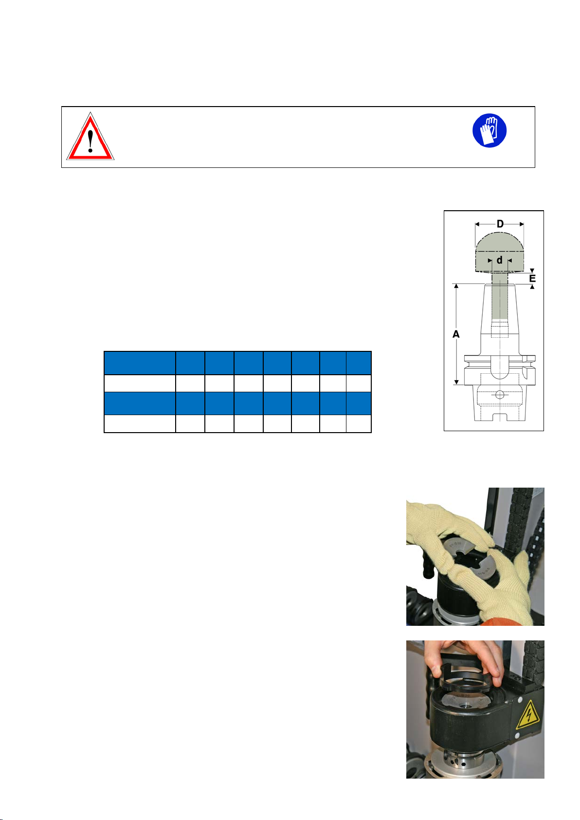
4.6. Shrinking of tools with larger front than shank
Wearing supplied protective gloves is imperative while handling the device and
Shrinkfit holders/tools.
4.6.1. Clearance between tool head and toolholder front face
Note: For tools with larger front end than shank, split heat focusing stoppers covering tool shank
diameter Ø 3-32 are available as accessories, capacities : Ø 3-6, Ø 8-14, Ø 16-18, Ø 20-25, Ø 32
mm.
To successfully shrink/release special tools,it is necessary to observe the following conditions:
-Maximal diameter of the cutter Dis 3 x d
-Ø Dmaximum = Ø63 mm (maximum bore Ø ofinductionunit).
-Adimension = 70 mm minimum (due to the inductor housing dimension).
-Edimension changes dependingon tool shank diameter d: see chart below.
4.6.2. Shrinking procedure for tools with larger front than shank
Assemble the two split heat focusing stoppers that correspond to the tool shank Ø and install
them into the location diameter in the inductor housing.
Fit the lock ring in place to retain the split heat focusing stopper in the inductor housing.
Start the heating cycle as for a standard tool (see § 4.3.4.).
Tool shank d Ø
(mm)
3456810 12
Dimension E (mm)
66,5 77,5 78,5 9,5
Tool shank d Ø
(mm)
14 16 18 20 25 32
Dimension E (mm)
11 8,5 9776,5
20
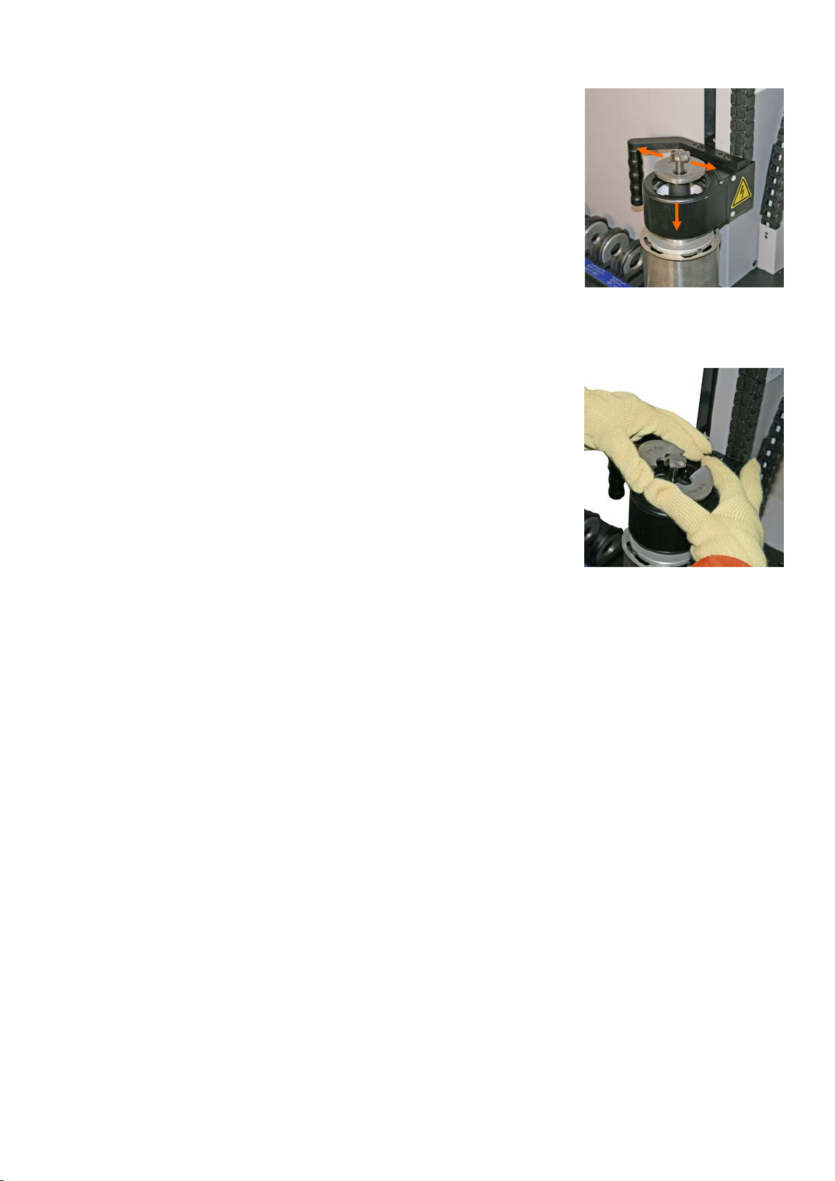
After shrinking, remove the lock ring and move the inductor housing downwards, exposing
the split heat focusing stopper. Remove the split heat focusing stoppers (caution: they may
be hot).
Move the inductorhousing upwards to allow the toolholder to be removed.
Note: Overall height of the inductor housing limits « A » dimension to 70 minimum. Any less
than this and it will not be possible to lower the inductor housing sufficiently to gain access to
the split heat focusing stopper assembly.
4.6.3. Shrink-releasing procedure for tools with larger front than shank
1) Move the inductor housing below the front face of the toolholder and fit the appropriate
split heat focusing stopper assembly around the shank of the cutting tool.
2) Move the inductor housing upwards so that the split heat focusing stoppers seat in the
inductor housing location diameter.
3) Fit the locking ring.
4) Start the heating cycle as for a standard tool (see § 4.3.4.).
5) On completion of the heating cycle move the inductor housing upwards in order to extract
the tool from the toolholder.
After the end of the heating cycle, move the universal sliding support along with the hot toolholder on a cooling slot and cover it
with an air cooling cone or use a complementary cooling device.
2
1
Table of contents
Other Seco Industrial Equipment manuals


