ABB ACS880 Series User manual

—
ABB INDUSTRIAL DRIVES
ACS880 multidrives cabinets
Mechanical installation instructions


Table of contents
1 Mechanical installation
7Contents of this chapter ........................................................................
7Examining the installation site ................................................................
7Necessary tools ...................................................................................
8Examining the delivery ..........................................................................
9Moving and unpacking the drive ..............................................................
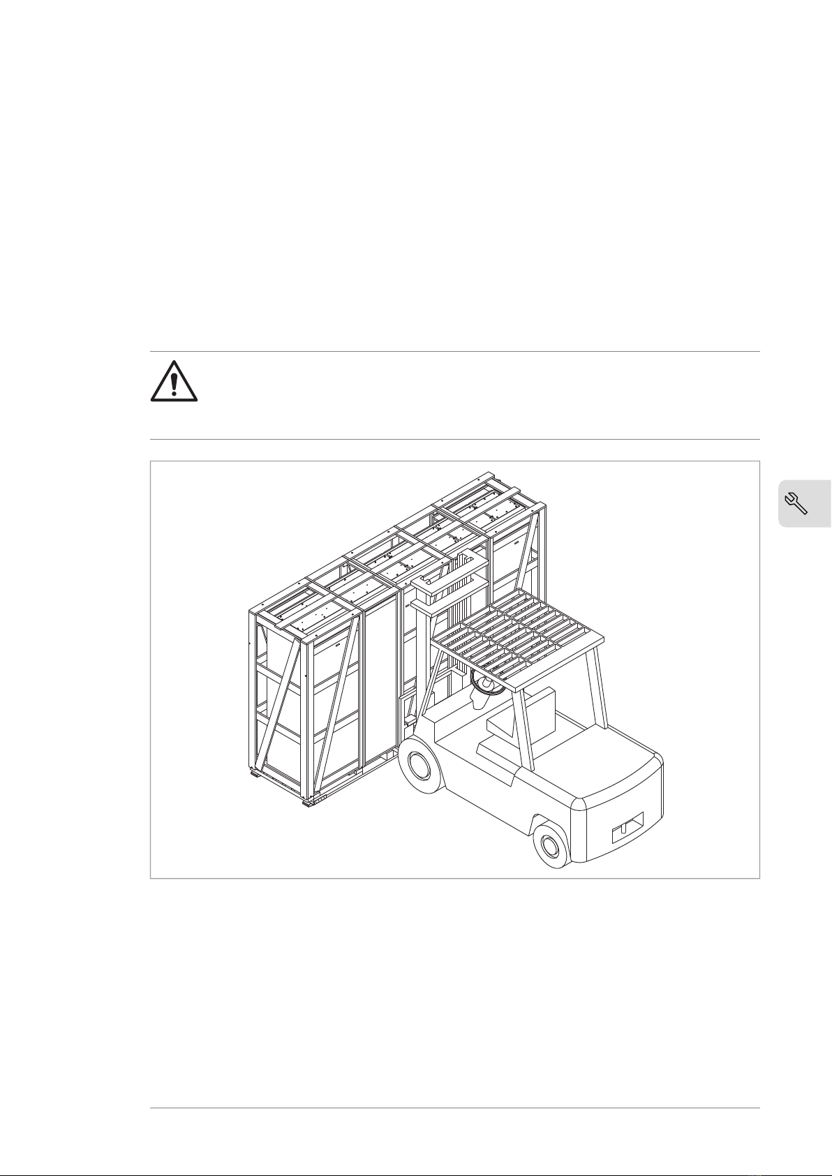
9Moving the drive in its packaging .........................................................
9Lifting the crate with a forklift .........................................................
10Lifting the crate with a crane ...........................................................
11Moving the crate with a forklift ........................................................
11Removing the transport package .........................................................
12Moving the unpacked drive cabinet .......................................................
12Lifting the cabinet with a crane ........................................................
13Moving the cabinet on rollers ...........................................................
13Moving the cabinet on its back .........................................................
14Final placement of the cabinet .........................................................
15Attaching the cabinet to the floor and wall or roof ... .. .. .. .. .. .. .. .. .. .. .. .. .. .. .. .. .. ..
15General rules ...................................................................................
16Attaching the cabinet (non-marine units) ...............................................
16Alternative 1 – Clamping .................................................................
17Alternative 2 – Using the holes inside the cabinet .. .. .. .. .. .. .. .. .. .. .. .. .. .. .. .. ..
18Attaching the cabinet (marine units) .....................................................
19Joining cabinet sections together ............................................................
23Miscellaneous .....................................................................................
23Cable duct in the floor below the cabinet ................................................
23Arc welding .....................................................................................
23Air inlet through the bottom of the cabinet (option +C128) .. .. .. .. .. .. .. .. .. .. .. .. .
24Air outlet duct on the cabinet roof (option +C130) ....................................
25Calculating the required static pressure difference .. .. .. .. .. .. .. .. .. .. .. .. .. .. .. .
26Lifting lugs and bars .............................................................................
26Certificate of conformity ....................................................................
26Declarations of conformity .................................................................
Further information
Table of contents 5

6

Mechanical installation
Contents of this chapter
This chapter describes the mechanical installation procedure of the drive.
Examining the installation site
Examine the installation site. Make sure that:
• The installation site is sufficiently ventilated or cooled to remove heat from the
drive. See the technical data.
• The ambient conditions of the drive meet the specifications. See the technical
data.
• The material behind, above and below the drive is non-flammable.
• There is sufficient free space above the drive for cooling, maintenance, and
operation of the pressure relief (if present).
• The floor that the drive cabinet is installed on is of non-flammable material, as
smooth as possible, and strong enough to support the weight of the unit. Check
the floor flatness with a spirit level. The maximum allowed deviation from the
surface level is 5 mm (0.2 in) in every 3 meters (10 ft). Level the installation site, if
necessary, as the cabinet is not equipped with adjustable feet.
Necessary tools
The tools required for moving the unit to its final position, fastening it to the floor
and wall and tightening the connections are listed below:
•crane, fork-lift or pallet truck (check load capacity!), slate/spud bar, jack and rollers
• Pozidriv and Torx screwdrivers
1
Mechanical installation 7
10

• torque wrench
• set of wrenches or sockets.
Examining the delivery
The drive delivery contains:
• drive cabinet line-up
• optional modules (if ordered) installed onto the control unit(s) at the factory
• appropriate drive and optional module manuals
• delivery documents.
Make sure that there are no signs of damage. Before attempting installation and
operation, see the information on the type designation labels of the drive to verify
that the delivery is of the correct type.
8 Mechanical installation
4

Moving and unpacking the drive
Move the drive in its original packaging to the installation site as shown below to avoid
damaging the cabinet surfaces and door devices. When you are using a pallet truck,
check its load capacity before you move the drive.
The drive cabinet is to be moved in the upright position.
The center of gravity of the cabinet is high. Be therefore careful when moving the unit.
Avoid tilting.
■Moving the drive in its packaging
Lifting the crate with a forklift
WARNING!
Incorrect lifting can cause danger or damage. Obey the local laws and
regulations applicable to lifting, such as requirements for planning the lift, for
capacity and condition of lifting equipment, and for training of personnel.
Mechanical installation 9
10

Lifting the crate with a crane
WARNING!
Incorrect lifting can cause danger or damage. Obey the local laws and
regulations applicable to lifting, such as requirements for planning the lift, for
capacity and condition of lifting equipment, and for training of personnel.
max 20
b
a
Lifting pointa
Optimal position for the lifting sling: as close to the traverse board as possibleb
10 Mechanical installation
4

Moving the crate with a forklift
Mechanical installation 61
Moving the crate with a forklift
750 mm (29.5'')
■Removing the transport package
Remove the transport package as follows:
1. Undo the screws that attach the wooden parts of the transport crate to each
other.
2. Remove the wooden parts.
3. Remove the clamps with which the drive cabinet is mounted onto the transport
pallet by undoing the fastening screws.
4. Remove the plastic wrapping.
Mechanical installation 11
10

■Moving the unpacked drive cabinet
Lifting the cabinet with a crane
WARNING!
Incorrect lifting can cause danger or damage. Obey the local laws and
regulations applicable to lifting, such as requirements for planning the lift, for
capacity and condition of lifting equipment, and for training of personnel.
Lift the drive cabinet by its designated lifting points. Depending on the size of the
cabinet, it has either bolt-on lifting lugs, or lifting bars with lifting holes.
Note: The minimum allowed height of the lifting slings with IP54 units is 2 meters
(6’7”).
62 Mechanical installation
Removing the transport package
Remove the transport package as follows:
1. Undo the screws that attach the wooden parts of the transport crate together.
2. Remove the wooden parts.
3. Remove the clamps with which the drive cabinet is mounted onto the transport pallet
by undoing the fastening screws.
4. Remove the plastic wrapping.
Moving the unpacked drive cabinet
Lifting the cabinet with a crane
Lift the drive cabinet using its lifting eyes. The lifting eyes can be removed after the cabinet
is in its final position, but their mounting holes must be blocked to retain the degree of
protection.
Note: The minimum allowed height of the lifting slings with IP54 units is 2 meters (6’7”).
IP54
12 Mechanical installation
4

Moving the cabinet on rollers
WARNING!
Do not move marine versions (option +C121) on rollers.
Lay the cabinet on the rollers and move it carefully until close to its final location.
Remove the rollers by lifting the unit with a crane, forklift, pallet truck or jack.
Moving the cabinet on its back
If the cabinet needs to be laid on its back, support the cabinet from below alongside
the cubicle seams.
12
Cabinet back panel1
Support2
Mechanical installation 13
10

Final placement of the cabinet
Move the cabinet into its final position with a slate bar (spud bar). Place a piece of
wood between the edge of the cabinet and the bar to protect the cabinet frame.
14 Mechanical installation
4

Attaching the cabinet to the floor and wall or roof
■General rules
• The drive must be installed in an upright vertical position.
• Leave 400 mm (15.75”) of free space above the basic roof level of the cabinet for
cooling.
• The cabinet can be installed with its back against a wall (a), or back-to-back with
another unit (b).
• Leave some space (
w
) at the side where the cabinet outmost hinges are to allow
the doors to open sufficiently. The doors must open 120° to allow module
replacement.
a
b
120°
w
>400 mm (15.75”)
Note 1: Any height adjustment must be done before attaching the cabinet sections
to the floor or to each other. Height adjustment can be done by using metal shims
between the cabinet bottom and floor.
Note 2: Depending on the size of the cabinet, it has either bolt-on lifting eyes, or lifting
bars with lifting holes. Bolt-on lifting eyes need not be removed unless the holes are
used for attaching the cabinet. If the cabinet is delivered with lifting bars, remove
them and store them for decommissioning. Plug any unused holes using the existing
bolts and sealing rings included. Tighten to 70 N·m (52 lbf·ft).
Mechanical installation 15
10

WARNING!
Do not stand or walk on the cabinet roof. Make sure that nothing presses
against the roof, side or back plates or door. Do not store anything on the roof
while the drive is in operation.
■Attaching the cabinet (non-marine units)
Alternative 1 – Clamping
1. Insert the clamps (included) into the twin slots along the front and rear edges of
the cabinet frame body and fasten them to the floor with a bolt. The recommended
maximum distance between the clamps in the front edge is 800 mm (31.5”).
2. If floor mounting at the back is not possible, attach the top of the cabinet to the
wall with L-brackets (not included in the delivery) bolted to the lifting eye/bar
holes, and suitable hardware.
Attaching top to wallClamping bottom to floor
M16
16 Mechanical installation
4

Alternative 2 – Using the holes inside the cabinet
1. Attach the cabinet to the floor through the bottom fastening holes with size
M10…M12 (3/8”…1/2”) bolts. The recommended maximum distance between the
front edge fastening points is 800 mm (31.5”).
2. If the back fastening holes are not accessible, attach the top of the cabinet to the
wall with L-brackets (not included in the delivery) bolted to the lifting eye/bar
holes.
Attaching cabinet top to wallAttaching bottom to floor
M16
Mechanical installation 17
10

■Attaching the cabinet (marine units)
See the dimension drawing delivered with the drive for details of the fastening points.
Fasten the cabinet to the floor and roof (wall) as follows:
1. Bolt the unit to the floor through the flat bars at the base of the cabinet using
M10 or M12 screws.
2. If there is not enough room behind the cabinet for installation, clamp (a) the rear
edges of the flat bars (c) to the floor. See the figure below.
3. Attach corner brackets (d) to the lifting eye holes. Fasten the corner brackets to
the rear wall and/or roof with suitable hardware such as U-brackets (e).
M16
3
e
d
ab
c
2
Corner bracket (included)dClamp (not included)a
U-bracket (not included)eBack panel of cabinetb
--Flat bars at base of cabinetc
18 Mechanical installation
4

Joining cabinet sections together
Wide cabinet line-ups are delivered in multiple sections. The sections must be joined
together at the installation site. There is a joining cubicle at the end of a section for
this purpose. The screws for joining the sections are in a plastic bag inside the cabinet.
1. Attach the first section to the floor.
2. Remove any plates covering the rear post of the joining cubicle.
3. Align the two sections. The illustration below shows the placement of the sections.
a b c
First sectiona
Joining cubicleb
Second sectionc
4. Attach the front and rear posts of the joining cubicle to the posts of the other
section with 16 screws (8 per post). Tighten the screws to 5 N·m (3.7 lbf·ft).
5. Attach the second section to the floor.
Mechanical installation 19
10

6. Connect the PE (ground) busbars using the M10 bolts included. Tighten to
35…40 N·m (25…30 lbf·ft). If necessary, adjust the connection between two PE
busbars with the spacer plates (included in the delivery).
a
b
c
d
e
e
Bolta
Spring washerb
Plain washerc
Self-clinching nutd
Spacer platee
7. Remove the shroud covering the DC busbars in the joining cubicle.
20 Mechanical installation
4
Other manuals for ACS880 Series
34
Table of contents
Other ABB Industrial Equipment manuals
Popular Industrial Equipment manuals by other brands

Behncke
Behncke QWT Series Installation instruction

schmersal
schmersal AZM201Z-I1-ST2-T-1P2PW Instructions for operation

Endress+Hauser
Endress+Hauser Cleanfit CPA875 operating instructions

Rheem
Rheem Crossflow RD200 Owner's guide and installation instructions

SUHNER ABRASIVE
SUHNER ABRASIVE ROTOmax 4.0 Technical document

SAMCHULLY
SAMCHULLY TS Series instruction manual