Securitytronix ST-WD650PTZMINI-12X User manual

INSTALLATION MANUAL
ST-WD650PTZMINI-12X
High Speed Intelligent Dome PTZ Color Camera
This is a 12 volt DC camera.
Copyright North American Cable Equipment

2
PACKAGE CONTENTS
This package contains:
One ST-WD650PTZMINI-12X intelligent dome camera
One Mounting Arm
One installation manual
Note: The ST-WD650PTZMINI-12X requires a minimum 12VDC 1000mA
(1 Amp) power supply such as the ST-PS12VDC1A or ST-PS12VDC2A.
PRODUCT DESCRIPTION
The ST-WD650PTZMINI-12X is a professional grade, IP-66 rated outdoor
dome color camera with pan, tilt and zoom (PTZ) capability. The camera’s
design allows the saving of all settings in non-volatile memory. The
camera features include a 12X optical zoom 5mm – 60mm lens and a
Sony Super HAD II Color CCD with 650TVL color / 700TVL B&W
resolution.

3
SPECIFICATIONS
ST-WD650PTZMINI-12X
Specifications (Typical)
1.Image Sensor
1/3" Super HAD II Sony Color CCD
2
Resolution
Color 650TVL, Black 700TVL
3. Lens
5-60mm dynamic varifocal lens
4.
Effective Picture Elements
NTSC:976(H)×494(V)
5.
Minimum Illumination
0.001 Lux
6.
Scanning System
2:1 interlace
7.
Video Output
1Vpp, 75Ω
8. Signal to Noise Ratio
50dB
9.
Synchronous System
Internal, Negative sync.
10.
Auto Electronic Shutter
NTSC: 1/60s~1/100,000s,
11.
Gama Correction
0.45
12.
Gain Control
Auto
13.
White Balance
Auto / Manual
14.
Pan Range
360° continuous
15.
Tilt Range
0° ~ 90°
16.
Pan Speed
60° / second
17. Power
12VDC / 1A
18.
Storage Temperature
-22° F ~ 140° F
19.
Operating Temperature
14° F ~ 113° F
20.
Dimensions
8” x 8.5”
21.
Weight
2.9 lbs

4
INSTALLATION AND OPERATION
CAUTION: To reduce the risk of electrical shock do not remove the
cover or back of this unit. No user serviceable parts are inside.
CAUTION: To prevent electric shocks and risk of fire hazards, do
not use other than specified power source.
1. UNPACKING and HANDLING
Each unit is shipped factory tested.
Ensure that all accessories are removed from the container before
discarding packing material
2. MECHANICAL INSPECTION
Inspect the front and rear of the equipment for shipping damage.
Make sure the equipment is clean, and no connectors are broken,
damaged, or loose. If equipment appears to be damaged or
defective please contact your distributor or SecurityTronix at 1-610-
429-1511 for assistance.
This symbol is intended to alert the user to the presence of
important operating and maintenance (servicing) instructions.
This symbol is intended to alert the user to the presence of un-
insulated “dangerous voltage” within the product’s enclosure that
may be of sufficient magnitude to constitute a risk of electrical
shock.

5
3. ASSEMBLY
a. Remove the rear mounting plate, using the supplied allen key
wrench.
b. Guide the camera dome’s wiring harness through the hole in
the end of the mounting arm and out through the base of the
mount, being careful not to kink or scrape the wires.
c. Feed the stub of the camera dome into the hole in the
mounting arm, ensuring that the 3 threaded holes on the
camera tube align with the 3 holes in the mounting arm.
d. Using the 4 supplied Phillips head screws, attach the camera
dome to the mounting arm.
4. SPECIAL ATTENTION
a. The installer must comply with electrical safety standards.
There must be sufficient space between the camera’s power
supply and video line and any high voltage equipment and/or
cables.
b. Do not install the camera in an environment where the
temperature is above 114F.
c. Do not install the camera near a magnetic field or a high-
power motor.
d. Do not mount the camera near a radiator or heater.
e. The installation site and material must fully support the
weight of the product.
f. Only use a dry cloth to clean the camera. If there is dirt that is
difficult to remove wipe gently with a mild detergent. Never
use strong or abrasive detergents.
g. A 12VDC power supply at 1A or higher must be used. Using
an AC or other incorrect power supply will damage the
camera.
h. Only qualified installers are allowed to install, test and
disassemble the camera.
i. The camera is a low voltage product. If installed outdoors
proper safety and lightning grounding are required.
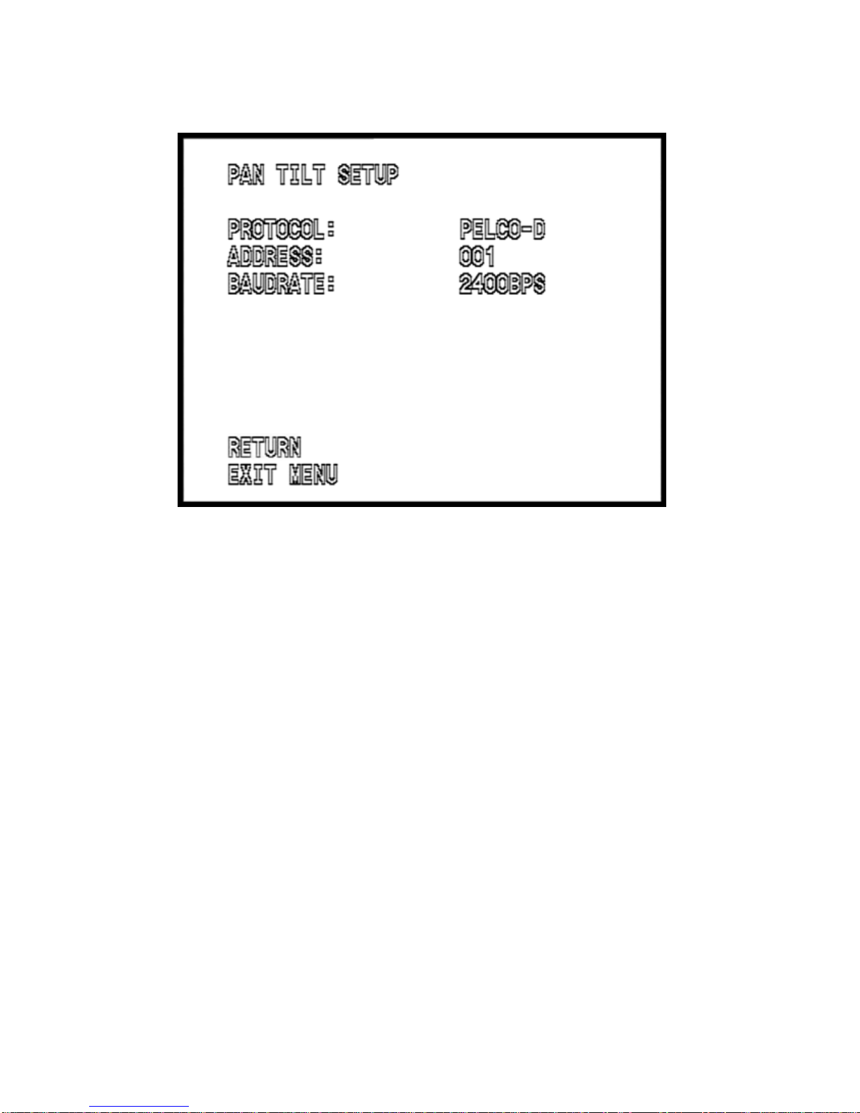
j. Before installing be sure the grounding, wiring, input power,
voltage, DIP switches, communication protocol and baud rate
are correctly set prior to powering up and using.

6
WIRING CONNECTIONS
a. Connect the power supply’s 12VDC plug to the camera’s
power jack.
b. Connect the camera’s BNC connector to a DVR (or monitor)
with a 75Ω coaxial video cable.
c. Connect unshielded twisted pair wire (UTP) between the
camera’s RS485 wires and the PTZ controller. The purple
wire is positive (A, +) and the grey wire is negative (B, -). Be
sure the same polarity is used at each end of the connection.
d. Connect the power supply’s AC plug to a suitable AC wall
outlet.

7
5. SETTING CAMERA ADDRESS, PROTOCOL and BAUD RATE
The camera’s address, protocol and baud rate are set using the camera’s
On Screen Display menu.
When the camera powers up, it will display the default protocol, address
and baud rate, which is:
Protocol: Pelco D
Address: 1
Baud rate: 9600
To access the menu, set your PTZ controller to match these default
settings then press “Iris Open” or “Open” on your PTZ controller.
The MAIN MENU will display:
Use the UP and DOWN buttons of your controller to highlight
PROTOCOL SETUP then press OPEN to access the PROTOCOL
SETUP menu.

8
The PROTOCOL SETUP menu will display:
Use the UP & DOWN buttons to select a parameter to change and use
the LEFT & RIGHT buttons to change the value. Then use the DOWN
button to highlight EXIT MENU and press OPEN to exit the menu.
NOTE:
The moment this menu is exited, the new settings will take place
and the PTZ controller will not operate the camera until it is set to
match the new settings of the camera.
NOTE:
9600 baud is only recommended for very short cable runs; 30 ~ 40 ft
or less. For best overall PTZ operation, it is strongly recommended
to use a baud rate of 2400 bps.

9
6.0 On Screen Display (OSD) Menus
This camera employs an on screen display system to facilitate
making changes to the camera’s settings.
The OSD is accessed by using the IRIS OPEN button (sometimes
labeled “OPEN” or “IRIS +”) of a Pelco D-compliant PTZ controller
or by using the controller to CALL preset 95.
When the menu appears it will display the MAIN MENU page:
The menu is navigated by using the UP & DOWN PTZ buttons to
move up and down through the menu, the RIGHT & LEFT buttons
to change values and the OPEN button to enter a sub-menu or
select a function such as EXIT MENU.

10
6.1 CAMERA SETUP MENU
From the MAIN MENU, use the DOWN button to highlight
CAMERA SETUP and use the OPEN button to access the
CAMERA SETUP menu.
The first page of two CAMERA SETUP menu pages will display:
Some menu options will have an arrow indicating that a sub-
menu is available. To access a sub-menu, highlight the menu item
and press OPEN.
From this page of the CAMERA SETUP MENU, highlight
SHUTTER / AGC to access the SHUTTER and Auto Gain Control
functions, which control how the camera will react to various
lighting conditions. Press OPEN to enter the sub-menu.
There are 2 different sub menus depending on whether this is set
to MANUAL or AUTO.

11
The SHUTTER / AGC MANUAL sub menu will display:
Use the UP, DOWN, LEFT & RIGHT buttons to navigate to the
desired function and change the setting, then navigate to RETURN
and press OPEN to return to page 1 of the CAMERA SETUP
MENU.
NOTE:
Manual setup of the shutter and AGC functions is only
recommended for extremely bright or dark conditions where
the light levels are consistent. In most cases using the AUTO
shutter and AGC settings is preferred.

12
To use AUTO shutter settings, change the SHUTTER / AGC
setting to AUTO and press OPEN to enter the AUTO SHUTTER
sub menu:
The SHUTTER / AGC AUTO sub menu will display:
Use the UP, DOWN, LEFT & RIGHT buttons to navigate to the
desired function and change the setting, then navigate to RETURN
and press OPEN to return to page 1 of the CAMERA SETUP
MENU.

13
6.2 WHITE BAL (white balance) MENU
From page 1 of the CAMERA SETUP MENU, highlight WHITE
BAL to access the white balance functions, which affects how the
camera will reproduce colors
There are 6 modes of white balance operation and 4 of the 6
choices have sub menus. USER 1 and USER 2 sub menus are
identical in operation:
MANUAL
ATW
USER 1
USER 2
Use the LEFT & RIGHT buttons to select the desired white
balance mode and press OPEN to enter the sub-menu.
WHITE BALANCE MANUAL MODE:

14
Use the LEFT & RIGHT buttons to change the WB LEVEL, then
select RETURN and press OPEN to return to the CAMERA
SETUP MENU page 1.
WHITE BALANCE ATW MODE:
Use the LEFT & RIGHT buttons to change the SPEED, DELAY,
ATW FRAME and EBVIRONMENT parameters, then select
RETURN and press OPEN to return to the CAMERA SETUP
MENU page 1.
NOTE:
In most cases using the default values of the ATW settings is
preferred.

15
WHITE BALANCE USER 1 & USER 2 MODE:
The USER 1 and USER 2 menus are identical in operation and
provide the same settings as ATW.
Use the LEFT & RIGHT buttons to change the SPEED, DELAY,
ATW FRAME and EBVIRONMENT parameters, then select
RETURN and press OPEN to return to the CAMERA SETUP
MENU page 1.

16
6.3 BACKLIGHT
From page 1 of the CAMERA SETUP MENU select BACKLIGHT
and use the LEFT & RIGHT buttons to choose:
OFF –No backlighting compensation is used.
BLC –Backlighting compensation is used. The intensity of
bright areas is reduced and the gain is increased for dark
areas to bring more definition to foreground objects when
there is a bright light present in the background.
HLC –bright areas are “blacked out” to prevent
oversaturation of the camera image.
6.4 PICT (picture) ADJUST
From page 1 of the CAMERA SETUP MENU select PICT ADJUST
and press OPEN to enter the sub menu.
The PICTURE ADJUST MENU will display:

17
Use the UP, DOWN, LEFT & RIGHT buttons to select and change
the MIRROR, BRIGHTNESS, CONTRAST, SHARPNESS, HUE
and GAIN parameters, then select RETURN and press OPEN to
return to the CAMERA SETUP MENU page 1.
NOTE:
The MIRROR function flips the camera’s image horizontally to
produce a “mirror image” of the actual camera view.
6.5 ATR (Adaptive Tone Reproduction)
From page 1 of the CAMERA SETUP MENU select ATR. If ATR is
set to ON a sub menu will become available. Press OPEN and the
ATR sub menu will display:
The ATR function provides gradation compensation to improve the
contrast of subjects whose gradation has been lost in cases

18
where, for instance, both low-luminance areas and high-luminance
areas exist in the same picture.
Use the UP, DOWN, LEFT & RIGHT buttons to select and change
the LUMINANCE and CONTRAST parameters, then select
RETURN and press OPEN to return to the CAMERA SETUP
MENU page 1.
6.6 MOTION DET (motion detection)
The Motion Detection feature is not implemented on this camera
model.
6.7 CAMERA SETUP MENU PAGE 2
From page 1 of the CAMERA SETUP MENU select NEXT and
CAMERA SETUP MENU page 2 will display:

19
6.8 PRIVACY
The PRIVACY feature is not implemented on this camera model.
6.9 DAY / NIGHT
From page 2 of the CAMERA SETUP MENU select DAY / NIGHT.
Use the LEFT & RIGHT buttons to choose one of 3 modes:
COLOR
AUTO
B/W
When set to COLOR, the camera is forced into color mode at all
times, regardless of lighting conditions.
The AUTO and B/W options each have a sub menu.
To use AUTO operation, choose AUTO then press OPEN and the
DAY / NIGHT AUTO sub menu will display:

20
NOTE:
In most cases using the default values of the DAY / NIGHT
AUTO settings is preferred.
Use the UP, DOWN, LEFT & RIGHT buttons to select and change
the 4 available parameters, then select RETURN and press OPEN
to return to the CAMERA SETUP MENU page 2.
6.10 DAY / NIGHT
From page 2 of the CAMERA SETUP MENU select
To use B / W operation, choose B / W then press OPEN and the
DAY / NIGHT B / W sub menu will display:
Use the UP, DOWN, LEFT & RIGHT buttons to select either ON or
OFF for the BURST parameter, then select RETURN and press
OPEN to return to the CAMERA SETUP MENU page 2.
Table of contents
Other Securitytronix Color Camera manuals