Sedna Aire Solar Cool SWM Single Guide
INSTALLATION MANUAL AND USERS GUIDE
Single Split Series – Ductless Split System Heatpump
04005020101 © Sedna Aire Europe GmbH 1 12/2012
SWM - Single Split Series
R-410A Ultra High Efficiency Ductless Heat Pump
2,6 – 7 kw Capacity
Sedna Aire now offers ductless single split heat pumps that use the more efficient and
environmentally friendly refrigerant (R-410A). The ductless system allows very easy
integration into existing surroundings without major investment in ducts or radiators. It
contains one outdoor and one indoor unit and is especially dedicated to straight forward
applications where only one indoor unit is needed.
The new SWM Series of Sedna Aire heat pumps offers outstanding performance as well
as environmental protection. These models with their high efficient compressors in DC-
Inverter technology offer when matched with our Solarcool
TM
panel efficiency rates 2-3
times better than current comparables best-in class systems: EER: 8 (Cooling) and COP:
8 (Heating).
SolarCool
TM…
The Hotter it Gets, The Better It Works!
INSTALLATION MANUAL AND USERS GUIDE
Single Split Series – Ductless Split System Heatpump
04005020101 © Sedna Aire Europe GmbH 2 12/2012
Table of Contents
Topic Page
1. Name and Descriptions of the parts 3
2. Instructions before installation and use 4
3. Remote Control Description and Manual 6
4. Battery change 7
5. How to operate the unit 7
6. Care and maintenance 9
7. Trouble shooting 11
8. Location of installation 13
9. Electric wiring 14
10. Installation indoor unit 18
11. Installation outdoor unit 20
12. Air purge and leakage test 21
13. Fill with refrigerant for connection pipes 21
14. Test operation 22
15. Check after installation 22
16. Warranty 23
IMPORTANT
The installation and especially the connection between the outdoor unit
and the Solarpanel shall be only performed by trained and skilled service
personnel having the appropriate instruments. Sedna Aire does not take
over any responsibility for direct and indirect damages causing from
installation by unskilled and/or untrained persons.

INSTALLATION MANUAL AND USERS GUIDE
Single Split Series – Ductless Split System Heatpump
04005020101 © Sedna Aire Europe GmbH 3 12/2012
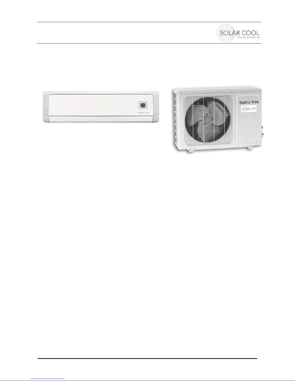
1. NAME AND DESCRIPTION OF THE PARTS
Indoor unit
Outdoor unit
Surface
p
anel
Air intake
Air outlet
Louve
r
Remote Control
Drain hose
Refrigerant
pipe and
connecting
wire
Condenser fan
Air intake
Air outlet
Setting Display

INSTALLATION MANUAL AND USERS GUIDE
Single Split Series – Ductless Split System Heatpump
04005020101 © Sedna Aire Europe GmbH 4 12/2012
2. INSTRUCTIONS BEFORE INSTALLATION AND USE
Earth: The Ground
wire of your outdoor
and indoor units must be
wired to the earth of your
electricity supply acc. To
local electrical building
codes. If this lacks, please
ask your service personnel
to install it. Don’t connect
the earth wire to gas pipes,
water pipes, drainage pipes
or any other improper
conductors.
★
Air conditioners are
to operate at 200-230V / 1
phase. All other voltages
are not permitted. They
may destroy the unit. Be
sure to have switched off
the power supply when you
are not using the unit for a
longer time
★
Don’t attempt to
repair the air conditioner
by yourself
Wrong repair may cause
an electric shock and may
kill you
★
Don’t apply cold
wind over longer time on
you
It may cause a cold and
harm your health,
especially over night when
you sleep.
★
If your detect unusual
phenomenons like smell
or burning smoke, turn
off immediately the unit. It
may cause damage,
electrical shocks and
impact your health.
★
Don’t place a heater
near the indoor unit of
the air conditioner. Air
flow from the combustion
can cause insufficient
heating up by the indoor
unit.
★
Don’t block the inlet
and outlet openings of
indoor and outdoor unit.
It can decrease the air
conditioning capacity or a
malfunction
★
Don’t step on the top
of the outdoor unit and
place something heavy
on it. Falling off the outdoor
unit may cause damage to
you and somebody else
★
Keep flammable
sprays and liquids at
least 1 m away from the
units.
It may cause fire or
explosion

INSTALLATION MANUAL AND USERS GUIDE
Single Split Series – Ductless Split System Heatpump
04005020101 © Sedna Aire Europe GmbH 5 12/2012
★
Please check, if the
planned stand is firm
If it is not, the unit may fall
down and cause injury
★
Select an appropriate
temperature depending
on outside temperature
Setting very low tempera-
tures consumes very much
electricity and money
★
Adjust direction of
airflow appropriately
Direct air flow by adjusting
the louvers for vertical and
horizontal direction by use
of remote control
★
Don’t leave windows
and doors open for a
longer time while running
the unit.
It can decrease the air
conditioning capacity
★
Don’t blow the air
directly to and plants.
It may impact their health,
when not properly
controlled
★
Don’t damage the
power and signal cords.
Don’t damage or cut the
cords. If this has happened,
contact service center or
other trained and skilled
electricians, since wrong
repairs may kill you.
★
Don’t splash water on
the indoor units.
It can cause an electric
shock and kill you
★
Don’t insert your
hands or stick into the air
intake or outlet vents
It destroy the air guidance
and unit.
★
Don’t use the air
conditioner for any other
as not designed purposes
like, drying clothes, food,
etc. It may overheat and
the unit may be damaged.
Max 5 °C
difference bet-
ween in and
out
Louver left/
right adjust-
ment
Louver Top/
down adjust-
ment
INSTALLATION MANUAL AND USERS GUIDE
Single Split Series – Ductless Split System Heatpump
04005020101 © Sedna Aire Europe GmbH 6 12/2012
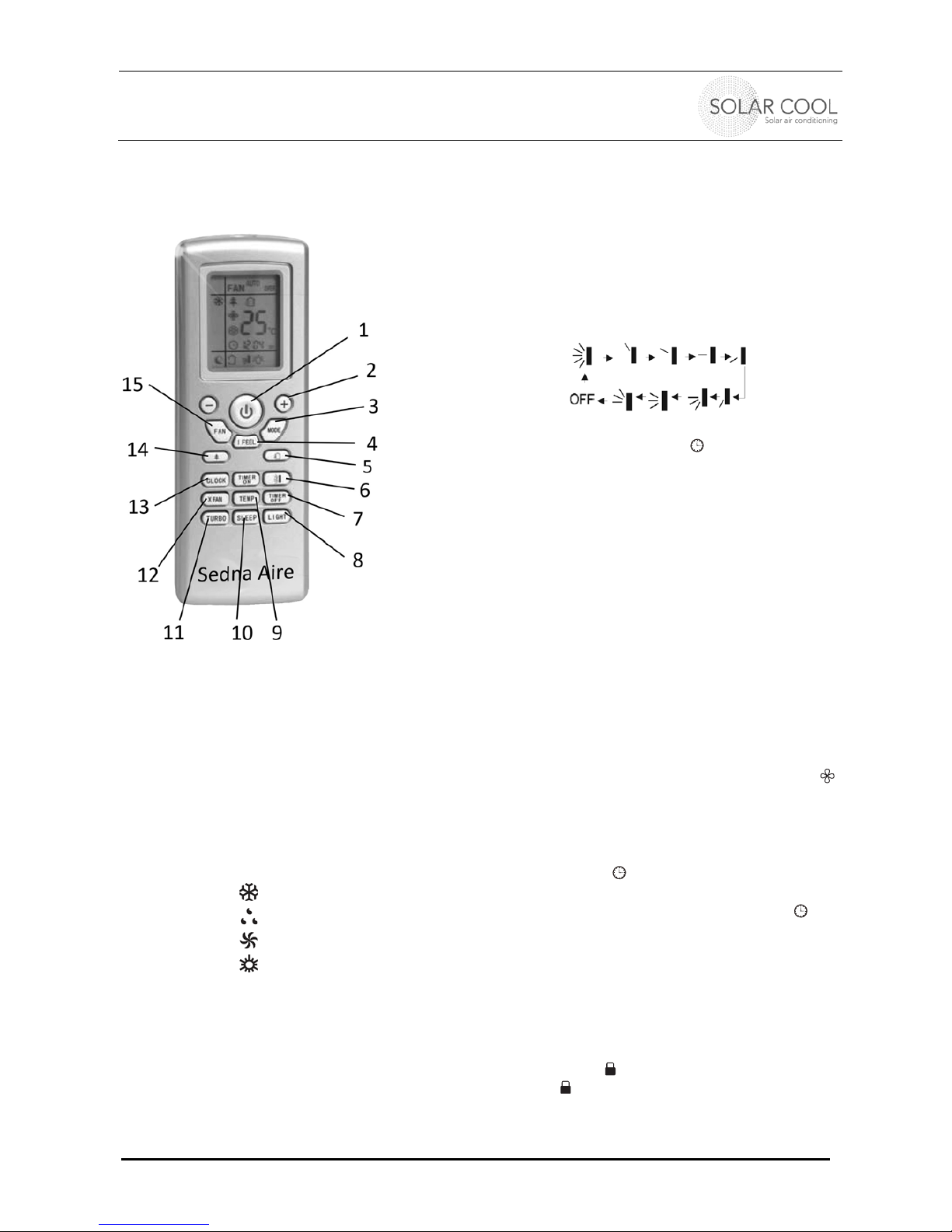
3. REMOTE CONTROL DESCRIPTION AND MANUAL
Actual remote control may vary, but functionality remains
1 Turns unit on and off
2 Adjusts Temperature setting: (not in
Auto mode)
+ to increase temperature, hold 2 sec.
for fast change
- to decrease temperature
3 Change operation mode:
press the mode button until you see the
desired mode
- Auto, sets automatically
- Cool
- Dry
- Fan
- Heat
4 “I Feel” Enhanced Comfort:
Press the button to switch this function
on or off: Then the temperature sensor
in the remote control and not in the wall
unit will master the control.
5 Air Function:
Press to turn on or off
6 Swing Function: Press to set up&down swing
angle of air guide louvers. Various static
angles or a dynamic oscillating angle of the
louver may be chosen: The first sign on the
upper left row indicates the oscillating mode,
while the others install a static angle.
7 24 Hour timer: Switch TIMER ON/TIMER OFF
on or off. After pressing disappears and
“ON” blinks. 00:00 is displayed. Press within 5
sec. “+” or “-“ to set time. Every press changes
time by 1 min. Holding down the “+” “-“ buttons
rapidly changes the time setting by 1 min. and
then 10 min. After having set, press TIMER-
ON/TIMER OFF within 5 sec. to confirm your
input
8 Display light on/off: Switch display light on/off
9 Displays set temperature, room temperature or
outdoor temperature. The temperature control
range for the indoor unit is 16°C to 30°C.
10 “One Touch” sleep function: Press to set the
unit to sleeping mode or wake it up again (in
Cool, Dry, Heat mode)
11 Turbo Fan
Press the button to cool or heat faster
12 Indoor fan delay: Press to set a fan delay ( )
of 10 min. after you have turned off unit in
order to dry unit (only COOL& DRY mode)
13 Clock setting - to set current time
When pressed once, the clock setting mode
appears and blinks. Same logic as for the
timer setting. After having set, confirm your
choice by pressing “CLOCK” and then will
be constantly displayed
14 Plasma Ion Generator (if available)
Press the button to switch on or off
15 Adjustable 3-speed fan
Press the button and “+” or “-“ to increase or
decrease the desired fan speed
Lock: Press “+” and “-“ simultaneously to lock or
unlock. If locked, is displayed. When you press
any button, blinks 3 times
°F ↔°C: Switch unit off and press simultaneously
MODE and “-“
INSTALLATION MANUAL AND USERS GUIDE
Single Split Series – Ductless Split System Heatpump
04005020101 © Sedna Aire Europe GmbH 7 12/2012
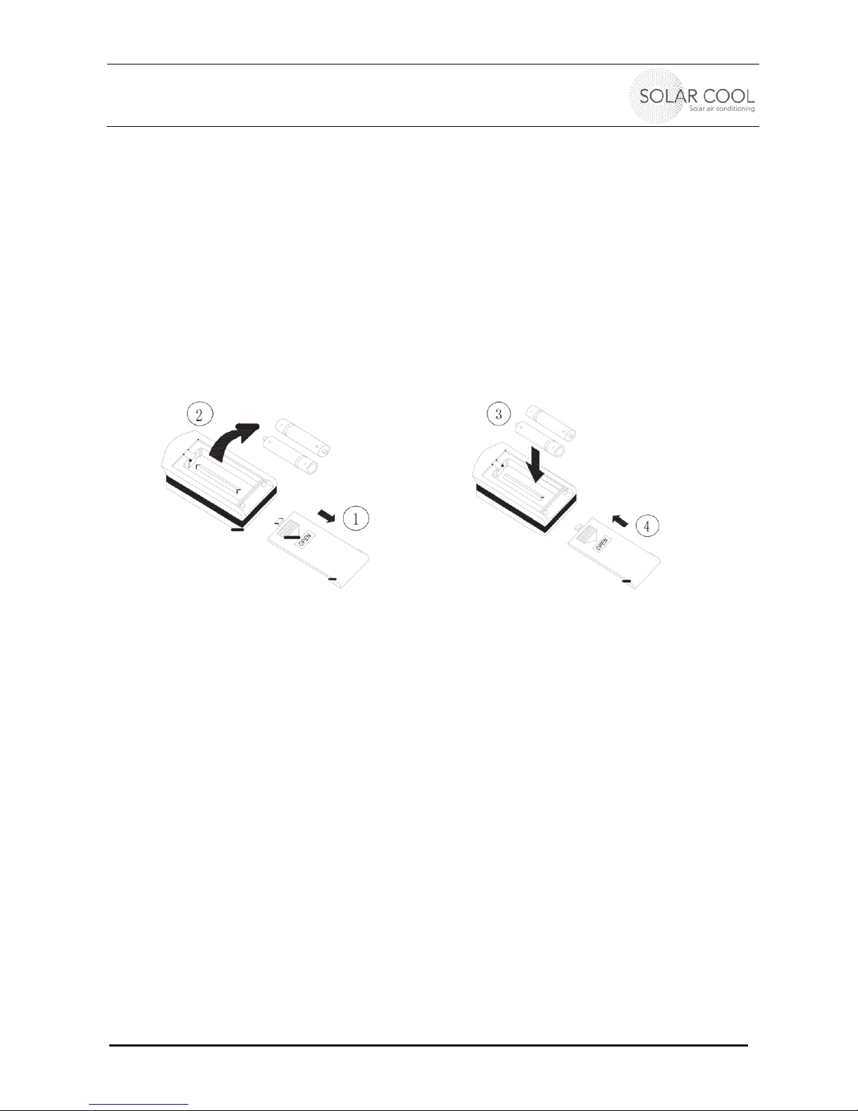
4. BATTERY CHANGE
1 Press lid and remove it
2 Take old batteries out (2 AAA dry cells)
3 Insert new batteries (2 AAA dry cells)
4 Insert lid again
NOTE
Don’t mix new and used batteries
Remove batteries when unit is not be used for a longer time
The batteries hold for appx. one year under usual conditions
The remote control should be 1 m away from television or audio device, since it could
interact under unfavorable conditions with them
Displace batteries correctly. They are not standard household waste.
5. HOW TO OPERATE THE UNIT
1 Connect the unit with power and set eventually breaker on and the buzzer will send a tone. In
the meantime the Power/Run indicator is red and the air conditioner is waiting to start.
(Note: Once the air conditioner is connected to power or it receives a signal from the remote
control, the buzzer will send out a tone)
2 When you press the ON/OFF button, the Power/Run indicator switches over to green and
shows the running mode (Cool, Heat, Auto). The air conditioner starts now to run.
3 Press the MODE button to switch between the various running modes.
4 Press the SWING button to start or stop the automatic swing mode of the indoor units
5 Press the FAN button to set the desired fan speed.
6 Press the TEMP button to set the desired room temperature. (This is controlled by a
temperature sensor in the indoor unit or in the “I FEEL” mode by a temperature sensor in the
remote control)
7 Press the SLEEP button to set the unit to sleep
8 Press the TIMER button to set a predefined start and Stop time, for example when you are
not around and want to get it started half an hour before you return
Note:
In the AUTO mode the unit will automatically adjust its running mode according to the
room
temperature
.

INSTALLATION MANUAL AND USERS GUIDE
Single Split Series – Ductless Split System Heatpump
04005020101 © Sedna Aire Europe GmbH 8 12/2012
SPECIAL FUNCTIONS IN THE COOLING MODE
Principle:
The air conditioner absorbs heat from indoor air and transmits it outdoors for discharge, hence to
decrease the indoor ambient temperature. The cooling capacity decreases with the rise of outdoor
ambient temperature.
Anti-freeze Function:
If the air conditioner is running in the low-temperature cooling, frost will appear on the surface of
the indoor heat exchanger. When the temperature of the indoor unit heat exchanger is decreased
to 0 °C or lower, the microcomputer control will stop the compressor to protect the complete unit.
SPECIAL FUNCTIONS IN THE HEATING MODE
Principle:
The air conditioner absorbs heat from outdoor air and transmits it indoors for emission, hence
to increase the air temperature in the room. The heating capacity decreases with decreasing
out door ambient temperature
It takes only a short time for this type of hot air circulating to increase the indoor temperature
Use this air conditioner with other heating equipment, if the outdoor temperature is extremely
low
Defrost:
When the outdoor temperature is low but the humidity is high, the heat exchanger of outdoor
unit may be frosted after the air conditioner has run for a period of time. This will decrease the
heating effect. ln this case, auto defrost function will be activated and the heating mode will
temporarily stopped for 8-10 minutes.
Both the indoor fan and outdoor fan will be stopped during auto defrost.
During defrost, the indicator on indoor unit will blink and steam might flow from the indoor unit.
This is caused by quick defrost other than fault.
Heating mode will automatically resume upon completion of defrost process.
Anti-cool Air Function:
In heating mode, if the indoor heat exchanger fails to reach a specific temperature under following
conditions, so the indoor fan will not be started, so as to avoid blowing of cold air (within 3 min.):
Start of heating mode
End of auto defrost
Heating under low-temperature environment
Conditions for the air conditioner unable to run normally:
Protection device might be activated within such temperature range as specified below, so that the
unit could be stopped
Heating mode: Outdoor temperature above 24°C, Outdoor temperature below -7°C, Room
temperature above 27°C
Cooling mode: Outdoor temperature above 43°C, Room temperature below 21°C
Dehumidify mode: Room temperature below 18°C
lf the unit is running for long time in the cool or humidify mode with relative humidity higher than
80% (door and windows are open), dew might drop near the air outlet.
INSTALLATION MANUAL AND USERS GUIDE
Single Split Series – Ductless Split System Heatpump
04005020101 © Sedna Aire Europe GmbH 9 12/2012
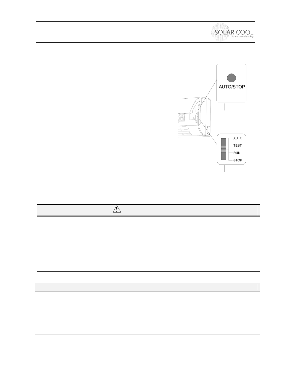
Emergency operation for lost remote control:
When the remote control was lost or is damaged, emergency
operation can be carried out as following:
Open the cover front surface lit and you will see two handling
switches. The manual switch is labeled AUTO/STOP, the other
code switch differentiates between four different modes
Manual switch: Press to switch between Auto mode
and Off. In the Auto mode the unit will run and set the
appropriate heating or cooling mode depending on set
temperatures and current measured room
temperature.
Code switch: Move the lever to Auto and the unit
starts the Auto mode as described above. Move it to
Stop and the units shuts off. TEST and RUN are only
for service personnel during installation.
6. CARE AND MAINTENANCE
CAUTION
Turn off power and pull out the power plug before cleaning the air
conditioner.
Never spray or sprinkle water on the indoor unit for cleaning. You may
get an electrical shock which could kill you
Volatile liquids /e.g. thinner or gasolines) will damage the air
conditioner. So wipe the units with a dry soft cloth or slightly
moistened with water or cleanser.
Clean the front panel
When the indoor unit front panel is dirty, please use a cloth which is slightly moistened with warm
water/cleanser under 40 °C, then dry it and wipe off the dirty spots.
NOTE:
The indoor units contains microcomputer components and circuit board in the display which are very
sensitive against water. So don’t put any water into the interior of the indoor unit.
Manual
switch
Code
switch
INSTALLATION MANUAL AND USERS GUIDE
Single Split Series – Ductless Split System Heatpump
04005020101 © Sedna Aire Europe GmbH 10 12/2012
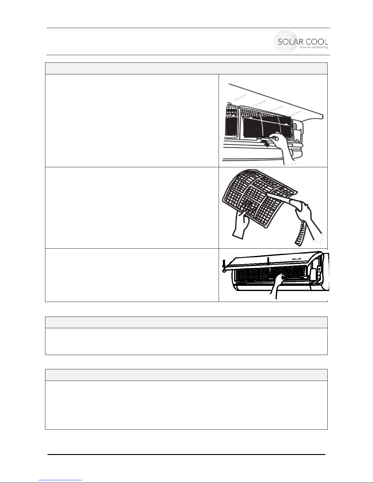
Clean the air filters in the indoor unit - (all 3 months recommended)
Take out the air filters:
Open the surface panel, hold the tab of the air filter and
raise it slightly. Then take it out along the direction of the
arrows (see right figure)
Clean the filter
Use a vacuum cleaner for removing the dust from the
filter or
Wash them with water and a mild cleanser and dry
them in the shade (no full sun exposure)
NOTE: Before cleaning the unit, remove the displayer box
(if present) first, then wash the panel. Never use water
above 45°C to wash filter. This can cause deformation or
discoloration. Never parch it by fire, since this could cause
fire, deformation or discoloration.
Reinsert the filter
Reinsert the filter along the direction of the arrow, then
cover the surface panel and clasp it
Maintenance of outdoor unit
Turn power off
Clear dust from outdoor unit
Repaint the rubiginous place on
the
outdoor
unit to
prevent
it from spreading
Check before you use the unit
Be sure that nothing obstructs the air outlet and intake vents
Check that the unit is „earthened“, i.e. that the earth wire from the unit is connected with the
ground/earth of your power supply in the house.
Check whether the batteries in your remote control are still operational
Check if the outdoor unit is standing firm on its base or rack. If not, contact your service
center.
INSTALLATION MANUAL AND USERS GUIDE
Single Split Series – Ductless Split System Heatpump
04005020101 © Sedna Aire Europe GmbH 11 12/2012
7. TROUBLE SHOOTING
Don’t try to repair the air conditioner by yourself. It may cause an
electric shock and kill you or damage the unit. Contact authorized service center.
Following checks prior to contact may save you money
Fault Cause analysis
Air conditioner does not run upon
immediate restart after a stop
To protect the air conditioner upon immediate restart
after a stop, the microcomputer controller will delay the
unit for 3 minutes before the air conditioner will run.
Air conditioner blows out bad smell
when it
is
initially started.
The air conditioner itself has no bad smell. lf any, is the
bad smell accumulated from environment. Solution:
Clean the air filter . lf still any problem, the air
conditioner shall be cleaned (Please contact Authorized
Service Center)
You may hear "water flowing" noise
when the
air
conditioner is running.
When the air conditioner is started, or the compressor is
started or stopped during running or the air conditioner is
stopped, sometimes you may hear "hua-hua" or "di-du-
di-du" noise. This is the flowing sound of refrigerant
other than fault.
Sometimes a thin fog will flow out of
the
outlet
when air conditioner is
running in cooling mode.
This might occur when indoor temperature
and
humidity
are high. This is because the indoor air is quickly cooled
down.
After a period of time, the fog will disappear with the
decrease of indoor temperature and humidity.
You may hear a slight crack when the
air conditioner is started or stopped.
This is the sound of friction caused by expansion
of
panel
or other parts due to the change of temperature.
Air conditioner does not run.
Check if power
failure?
Has circuit protection device has tripped?
ls the voltage too high or too low? (To be tested by
professional technicians).
ls timer function correctly
used?
Air conditioner has poor cooling (or
heating)
effect.
Air inlet or outlet of outdoor unit blocked?
Air filter clogged by dust?
All doors and windows closed?
Air flow set to "LOW FAN"?
Any other heating source in the
room?
Proper temperature setting ?
Remote controller cannot execute
control.
Remote controller sometimes cannot execute control
if the air conditioner is subject to abnormal inter-
ference or frequent switch of functions.
To
resume
normal operation, just pull out the power and reinsert
it properly.
Is the remote control too far away from indoor unit or
blocked by any obstacles?
Check the battery in remote controller for power Ievel.
lf low power, replace the battery.
Check, if remote controller is damaged.
INSTALLATION MANUAL AND USERS GUIDE
Single Split Series – Ductless Split System Heatpump
04005020101 © Sedna Aire Europe GmbH 12 12/2012
Don’t try to repair the air conditioner by yourself. It may cause an
electric shock and kill you or damage the unit. Contact authorized service center.
Following checks prior to contact may save you money
Fault Cause analysis
Water leaks from indoor
unit.
Air humidity is too
high.
Condensing water overflows.
Joint of indoor unit drain pipe is loose.
Water leaks from outdoor
unit.
Under cooling mode, water might condense on pipe
or pipe joint due to cooling.
Defrosted water flows out under heating or defrost
(auto defrost) mode.
Under cooling mode, water attached on heat
exchanger will drip.
No air blows out from indoor unit.
When the temperature of indoor
heat
exchanger is
low during heating process, the indoor unit will stop
air blowing to prevent blowing of
cold
air (within 3
minutes).
In HEAT mode: when outdoor temperature is low or
humidity is high and much frost on the heat
exchanger has developed, unit switches into
automatic defrost mode. Indoor unit stops blowing air
for 3-12 min. During this water may flow out or steam
will appear
In dehumidify mode, the fan of indoor unit might be
stopped sometimes to prevent evaporation of
condensing water and inhibit the rise of temperature
Moisture exists on outlet grill.
lf the air conditioning is long running
under
high
humidity, moisture might condense on the grill and
drop down.
Indoor unit gives out noise.
The sound that the fan or compressor relay
is
switching (close/open).
Air conditioner may give out sounds under defrost
or when it is stopped. This is caused due to inverse
flow of refrigerant in the unit.
H1: Defrosting
Is normal
In the case of following events, please contact authorized service center
Air conditioner gives out shrill noise
during
running
.
Air conditioner gives out bad smell during running.
Water leaks indoors.
Air break switch or leakage protection switch trips
frequently
.
Liquids or water are poured into the machine or
remote controller.
Abnormal overheating of
power
cord and plug.
STOP THE AIR CONDITIONER AND
PULL OUT THE POWER PLUG
INSTALLATION MANUAL AND USERS GUIDE
Single Split Series – Ductless Split System Heatpump
04005020101 © Sedna Aire Europe GmbH 13 12/2012
8. LOCATION OF INSTALLATION
Choose a proper location for the indoor and outdoor unit
Indoor unit
The intake and outlet should not be covered, so that the outflowing air can reach all the parts
of the room
Install in a location, from where the condensation water can be drained easily out and that
allows a short and easy connection to the outdoor unit
Avoid close heat sources, steam or flammable gas
Choose a location which is strong enough to withstand the weight and vibration of the unit
Allow enough clearance space to have access for routine maintenance e.g. replacing the
filters .
The height of the installation should be min. 2,2 m above the floor.
Stay away 15 cm from the ceiling (measured from air intake to ceiling), 15 cm on the left and
right side of the unit to any walls.
Stay away at least 1m from other electric appliances like TV, audio devices etc.
Do not locate the indoor unit in the immediate proximity of a laundry, bath, shower, or
swimming pool.
Make sure you can access the plug after having installed the indoor unit.
Outdoor unit
Choose a locations that minimizes noise and airflow to the neighbors.
Select a location which allows enough ventilation for the fan of the outdoor unit.
Do not cover intake and outlet of the air of the condenser.
Choose a location which is strong enough to withstand the full weight and vibration of the
outdoor unit and permits safe installation.
Avoid any proximity to hazardous and flammable gases, liquids.
When handling the outdoor unit, keep it always upright. Handling must be done by qualified
people being able to handle heavy loads.
After having opened packaging, make sure that all equipments are undamaged and all parts at
right and available.
Make sure that clearance requirements are met. (As seen from the front):
Left side: min. 30 cm to any wall
Right side: min. 50 cm to any wall
Top: min. 50 cm to any cover
Front: min. 200 cm to any wall or greater obstacle
Back: min. 30 cm to any wall

INSTALLATION MANUAL AND USERS GUIDE
Single Split Series – Ductless Split System Heatpump
04005020101 © Sedna Aire Europe GmbH 14 12/2012
9. ELECTRICAL WIRING
All electrical work must be done according to local and national building codes and any other
local and national regulations covering any electrical work.
The rated voltage and exclusive circuit must be used. Check Type plate ! The diameter of the
supplied power cord cables should be sufficient, but check with your local codes.
Don’t pull the power cord too strong.
The air conditioner must be safely earthed. The earth wire must be connected to the special
ground of the power supply of your house. This has to be done by a certified and skilled
service personnel. Appropriate protection switches against leakage of electricity and safety
breakers have to be installed to protect life and the unit against damage, shortenings and
overloads of the supplying wiring system in the house. The service personnel has to check, if
these protection devices fit to local codes and the requirements of the air conditioner.
The air conditioner is class 1, so it must be earthed and grounded.
The yellow green wires are the earth wires and are not to be used for any other purposes.
They may not be cut off and are to fixed by the tapping screw.
The power supply must have an access for the earth wire of the air conditioner.
This unit is not intended to by used by persons with reduced physical, mental or sensory
capabilities or a lack of experience and knowledge, unless they are supervised for their safety
concerning the use of the appliance.
Condensate pump
Note: The device of condensate pump is not provided with this air conditioner unit. If you need
the device, you may order it and install it according to the electrical diagrams.
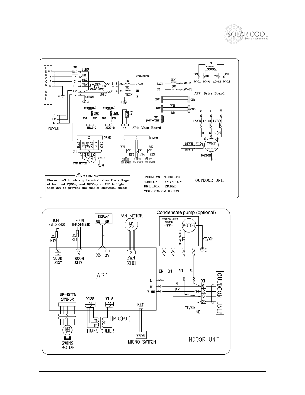
All following electrical charts are in English. They are for information and may vary. Check circuit
diagram sticked in the unit. Following index explains used word and acronyms:
BL: Black
BN: Brown
BL: Blue
RD: Red
YE/GN: Yellow/Green
POWER:
FAN MOTOR:
INDOOR UNIT:
COMP: Compressor
TEM: Temperature
SENSOR:
TUBE:
OUTROOM: Ambient temperature outside
EXHAUST: Outlet of the air
STEP MOTOR:
DISPLAY:
TRANSFORMER:
MAIN: Main board
PUMP: Condensate pump indoor unit

INSTALLATION MANUAL AND USERS GUIDE
Single Split Series – Ductless Split System Heatpump
04005020101 © Sedna Aire Europe GmbH 15 12/2012
SWM 09, 12 - 200-230V
INSTALLATION MANUAL AND USERS GUIDE
Single Split Series – Ductless Split System Heatpump
04005020101 © Sedna Aire Europe GmbH 16 12/2012
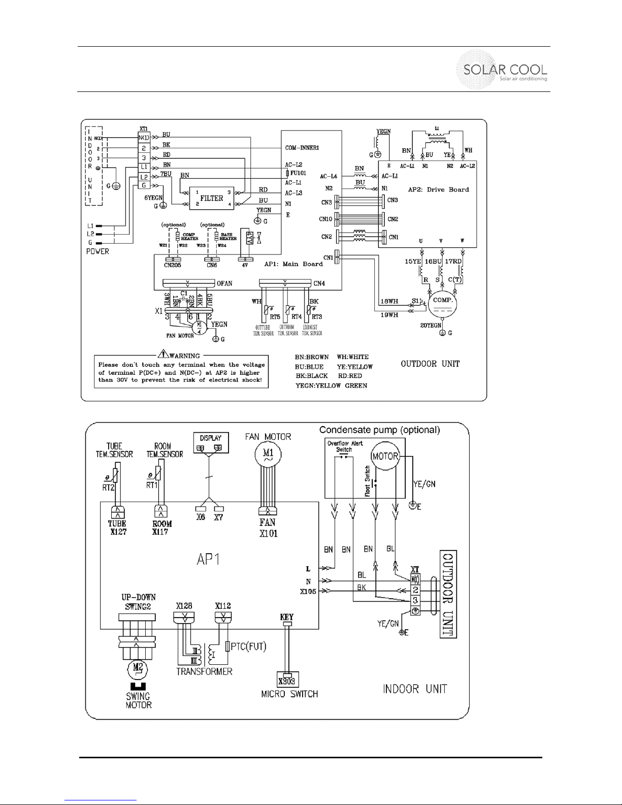
SWM 18 - 200-230V
INSTALLATION MANUAL AND USERS GUIDE
Single Split Series – Ductless Split System Heatpump
04005020101 © Sedna Aire Europe GmbH 17 12/2012
SWM 24 - 200-230V

INSTALLATION MANUAL AND USERS GUIDE
Single Split Series – Ductless Split System Heatpump
04005020101 © Sedna Aire Europe GmbH 18 12/2012
10. INSTALLATION OF THE INDOOR UNIT
Install the frame (rear panel)
Level with plumb line or leveler. As the drain outlet is
on the left side, it is better that the left side shall be
lower when adjusting the wall- mounted board
Use screws and dowels to secure the wall-mounting
frame on the wall
After installation is completed, check, if frame is
mounted safely. The frame has to withstand the
weight of 60kg and the fixing screws shall be able to
take up this stress.
Wall opening and pipe installation through wall
Drill a hole through the wall according to picture right
with a diameter of 65mm
Make sure the hole has a slight falling to the outside
to prevent coming water from outside
To prevent the fitting pipe and the cable passing
through the wall from being harmed and also protect
the hollow wall from rodents/insects, install a wall pipe
cover on both sides.
Fill the hole with foam/Sealing paste, after you have
made all other connections (Drainage, cables, etc.)
Install drain hose
The flexible drainage pipe must descend to the
outside in order to allow smooth running of water.
Connect the drain hose to the outlet of the indoor unit.
Bind the joint with rubber tape
Insert the drain hose into an insulating tube
Wrap the insulating tube with wide rubber tape to
prevent shifting of inner tube
Pay attention to avoid twists, ridges and distortion of
the drainage pipe in the Iayout and not to immerse the
outlet in water.
Wall
p
i
p
e
Seal
p
ad
Outlet pipe
indoor unit
Rubber tape
Drain hose
Outlet pipe
Outlet pipe
indoor unit Drain hose
Rubber tape
Insulating tube
Outlet pipe
indoor unit
Insulating tube
Connected
Bulge Distortion
Flooded
INSTALLATION MANUAL AND USERS GUIDE
Single Split Series – Ductless Split System Heatpump
04005020101 © Sedna Aire Europe GmbH 19 12/2012
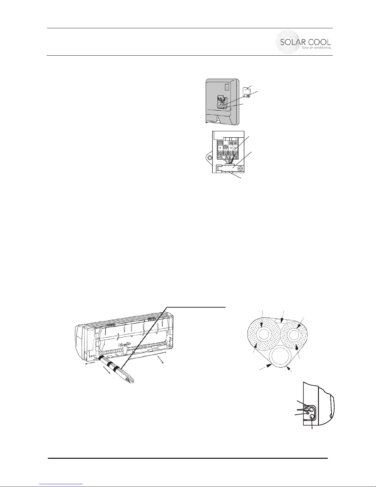
Connection of indoor and outdoor cables
Pull open the front panel of the indoor
Unscrew the screw fixing the covering plate of
terminal board.(See figure on the right)
Pass the power cable through a separate cable duct
on the back of indoor unit and pull it out from the front.
Connect the Neutral wire of the power connection
cables to the "N (1) "terminal of the terminal board,
connect the Signal wire to the "2" terminal, and
connect the L- wire to the "3" terminal and connect the
earthing wire to the (earth) terminal
Place the section of power cable with protective pipe
into pressing groove and close the cover plate.
Tighten the fixing screws to clamp the connecting
cable.
Put the front panel back into position
NOTES:
If the connecting cables are too short, replace the whole cable from outdoor to indoor unit by a longer cable.
No joints within the cable is allowed. Make sure you have the proper diameter for the extended length. When
the cable gets longer, you might need to choose a cable with thicker diameter for the copper conductor.
Don’t choose Aluminum conductors.
Be sure to connect the cable correctly. lncorrect connections will cause fault to some electrical parts.
Tighten the terminal screw to avoid looseness.
After tightening the screw, gently pull the cable for tightness. lncorrect connection of earthing cable might
cause electric shock.
Be sure to fix the junction cover plate securely and press it closely against connecting cable. lmproper
fixing of junction cover plate might allow dust or water to enter or expose connecting terminal directly
under the external force, whereas fire or electric shock might occur.
Install the indoor unit
The refrigerant pipe can come out from four directions,
i.e. right, rear right, left and rear left.
When positioning the refrigerant pipings (line) at the left or right side, cut
the tailings in the casing of the indoor unit in the appropriate size.
Wrap the piping (incl. cables) by using adhesive tape and pass them
through the cut-off-tailing holes .
Hung the claws at the rear side of the indoor unit to the hook on the wall-
mounting frame. Move the unit left and right to see if it is steady.
The installation height of the indoor unit must be at least 2,0 m.
Wiring cover
Wire clam
p
Right
Power cord
Left
Wrapping tape
Refrigerant
pipes
Power cord
Drainage hose
Right Rear
Terminal
N(1) - 2 - 3 - Earth/Ground)
Left Rear
Gas side
pipe insulation
Gas side pipe
Liquid side pipe
Electrical
wiring
Liquid side
pipe insulation
Drain hose Adhesive tape
INSTALLATION MANUAL AND USERS GUIDE
Single Split Series – Ductless Split System Heatpump
04005020101 © Sedna Aire Europe GmbH 20 12/2012
11. INSTALLATION OF THE OUTDOOR UNIT
Modify the outdoor unit and connect it to SolarCool panel:
Do this first ! See separate installation manual for SolarCool panel
Connecting the outdoor unit to indoor unit
The taper end of the connecting pipe must be in line with the corresponding
tape face of the valve joint. Tighten the nut of the connecting pipe and then
use spanner to tighten the nut.
Hexagon nut Torque (Nm)
Ø 6 - (1/4”) 15 - 20
Ø 9,5 - (3/8”) 31 - 35
Ø 12 - (1/2”) 50 - 55
Ø 16 - (5/8”) 60 - 65
Ø 19 - (3/4”) 70 - 75
NOTE: Connect the connecting pipe to the indoor unit first and then connect it to the outdoor unit. Pay
attention to the bending and Iayout when preparing the connecting pipe in order not to harm it. Do not screw
the joint nut too tightly, otherwise leakage will be caused.
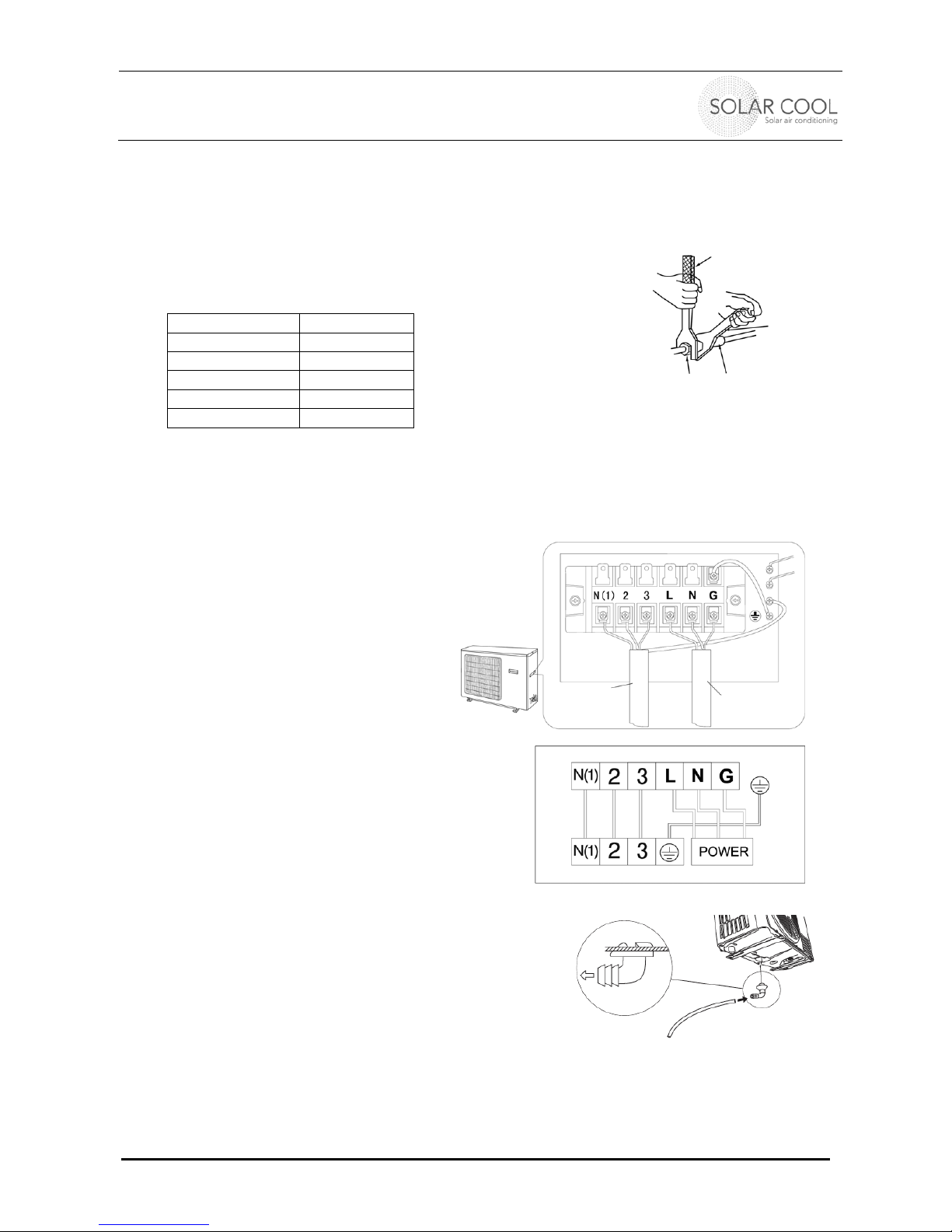
Connecting the cables and power supply at the outdoor unit
Remove the lid at the outdoor unit
Remove the cable clamp, connect the power
supply (L for hot/Live wire L2 or N for neutral
and G to Ground/Earth)
Connect the signal control cables of the
indoor units with the terminals at the lower row
of the terminal. Make sure that the wiring is in
accordance with the indoor unit.
Fix the wiring with the cable clamps.
Make sure that the wiring has been connected
securely
Reassemble the lid on the outdoor unit
NOTE:
Wrong wiring will cause electrical malfunction
and may damage the unit, harm your health
and might even kill you.
Do not pull the wires when you fix them with
the clamps
Drainage of outdoor unit
When the air-conditioning runs in the heating mode, the
condensate water generated at the outdoor unit and the
water generated by defrosting shall be drained through
the drainage hose to a proper place.
Installation: Insert the drainage hose into the ø 25 mm
(1”) hole in the base plate of the outdoor unit. Connect the
other end of the drainage hose an appropriate place to
remove all the upcoming water.
Mounting
Mount the outdoor unit with heavy and suited bolts on to the ground or an appropriate rack. Perpendicular
ground plates provide four holes for mounting. Make sure that the outdoor unit is assembled safe and may
withstand vibrations, major wind and other weather forces.
Torque wrench
S
p
anner
Signal
Control
Cable
Connecting Block for outdoor unit
Connecting Block for indoor unit
Diagram
Drainage hose
Flare
nut
Join
t
Table of contents
Other Sedna Aire Air Conditioner manuals


