LG ART COOL LA181HSV5 Installation and operation manual

SINGLE ZONE
ART COOLTM MIRROR
WALL MOUNTED
ENGINEERING MANUAL
Single Zone Art Cool Mirror Systems
3/4 to 2 Tons
Models:
LA090HSV5
LA120HSV5
LA181HSV5

For continual product development, LG Electronics U.S.A., Inc., reserves the right to change specifications without notice.
© LG Electronics U.S.A., Inc.
PROPRIETARY DATA NOTICE
This document, as well as all reports, illustrations, data, information,
and other materials are the property of LG Electronics U.S.A., Inc., and are
disclosed by LG Electronics U.S.A., Inc. only in confidence.
This document is for design purposes only.
A summary list of safety precautions is on page 3.
For more technical materials such as submittals, catalogs, installation,
owner’s, and service manuals, visit www.lghvac.com.
Proper sizing and installation of equipment is critical to achieve optimal performance. Split system air conditioners and heat pumps
(excluding ductless systems) must be matched with appropriate coil components to meet ENERGY STAR® criteria. Ask your contractor for
details or visit www.energystar.gov.
(ENERGY STAR and the ENERGY STAR mark are registered trademarks owned by the U.S. Environmental Protection Agency.)
This document, as well as all reports, illustrations, data, information, and other materials are the property of LG Electronics U.S.A., Inc.

TABLE OF CONTENTS
TABLE OF SYMBOLS
DANGER
This symbol indicates an imminently hazardous situation which, if not avoided, will result in death or
serious injury.
WARNING
This symbol indicates a potentially hazardous situation which, if not avoided, could result in death or
serious injury.
CAUTION
This symbol indicates a potentially hazardous situation which, if not avoided, may result in minor or
moderate injury.
Note:
This symbol indicates situations that may result in equipment or property damage accidents only.
This symbol indicates an action that must not be performed.
Unit Nomenclature...........................................................................................................................................................................................................4
LG Air Conditioner Technical Solution (LATS)..........................................................................................................................................................5-6
Art Cool Mirror Product Data.....................................................................................................................................................................................7-36
Mechanical Specications ......................................................................................................................................................................................... 8
General Data ......................................................................................................................................................................................................... 9
Electrical Data ............................................................................................................................................................................................................ 11
Functions, Controls, and Options .......................................................................................................................................................................... 12
Dimensions............................................................................................................................................................................................................13-17
Acoustic Data ........................................................................................................................................................................................................ 18-21
Refrigerant Flow Diagrams .................................................................................................................................................................................... 22-23
Wiring Diagrams.................................................................................................................................................................................................... 24-26
Electrical Connections ........................................................................................................................................................................................... 27-30
Air Flow and Temperature Distribution ................................................................................................................................................................ 31-34
Accessories ........................................................................................................................................................................................................... 35-36
Art Cool Mirror Performance Data--------------------------------------------------------------------------------------------------------------------------------------------- 37-49
Cooling Capacity Data ...........................................................................................................................................................................................38-40
Maximum Cooling Capacity Data .......................................................................................................................................................................... 41-43
Heating Capacity Data ........................................................................................................................................................................................... 44-45
Maximum Heating Capacity Data .......................................................................................................................................................................... 46-47
Equipment Selection Procedure ............................................................................................................................................................................ 48-49
Art Cool Mirror Application Guidelines................................................................................................................................................................ 50-59
Placement Considerations ..................................................................................................................................................................................... 51-55
Installing Outdoor Unit Indoors .............................................................................................................................................................................. 56-58
Refrigerant Piping Design ...................................................................................................................................................................................... 59
Due to our policy of continuous product innovation, some specications may change without notication.
©LG Electronics U.S.A., Inc., Englewood Cliffs, NJ. All rights reserved. “LG” is a registered trademark of LG Corp. INTRODUCTION | 3
Introduction

UNIT NOMENCLATURE
A120 H
System Type:
Style:
SV = High Efficiency Inverter
VP = Gallery
YV = Premier
EV = Mega
V = Standard Inverter
T = Thermostat Compatible
LV = Extended Piping
Capacity
(Cooling capacity in Btu/h):
Frame Type:
A: Art Cool™
S: Standard
C: Four-Way Ceiling-Cassette
D: Ceiling-Concealed Duct (Low Static)
H: Ceiling-Concealed Duct (High Static)
V: Vertical-Horizontal Air Handling
L = LG
9 = 9,000
12 = 12,000
18 = 18,000
24 = 24,000
36 = 36,000
42 = 42,000
48 = 48,000
LSV 5N
N: Indoor Unit
U: Outdoor Unit
No N or U: System
H = Heat Pump
Indoor Units and Outdoor Units
Generation or Revision
1 = First
2 = Second
3 = Third
4 = Fourth
5 = Fifth
Due to our policy of continuous product innovation, some specications may change without notication.
©LG Electronics U.S.A., Inc., Englewood Cliffs, NJ. All rights reserved. “LG” is a registered trademark of LG Corp.
4|INTRODUCTION
Single Zone Art CoolTM Mirror Wall Mount Engineering Manual

LG AIR CONDITIONER
TECHNICAL SOLUTION (LATS)
LG Air Conditioner Technical Solution (LATS) Software
A properly designed and installed refrigerant piping system is critical to the optimal performance of LG air-conditioning systems. To assist
engineers, LG offers, free of charge, LG Air Conditioner Technical Solution (LATS) software—a total design solution for LG air conditioning
systems. Contact your LG Rep for the best software program for your application.
To reduce the risk of designing an improper applied system or one that will not operate correctly, LG requires that LATS software be used on all projects.
Formats
LATS is available to LG customers in three user interfaces: LATS HVAC, LATS CAD2, and LATS Revit. All three LATS formats are available
through www.myLGHVAC.com, or contact an LG Sales Representative.
LATS HVAC is a Windows®-based application that aids engineers in designing LG Variable Refrigerant Flow (VRF), Multi F / Multi F MAX,
Single-Zone, and Energy Recovery Ventilator (ERV) systems.
*Windows®is a registered mark of Microsoft®Corporation.
LATS CAD2 combines the LG LATS program with AutoCAD®
software**. It permits engineers to layout and validate LG Multi V
Variable Refrigerant Flow (VRF), Multi F / Multi F MAX, Single-Zone,
and Energy Recovery Ventilator (ERV) systems directly into CAD
drawings.
LATS Revit integrates the LG LATS program with Revit®software**.
It permits engineers to layout and validate Multi V VRF systems
directly into Revit drawings.
**AutoCAD® and Revit® are both registered marks of Autodesk, Inc.
Features
All LG product design criteria have been loaded into the program,
making LATS simple to use: double click or drag and drop the com-
ponent choices. Build systems in Tree Mode where the refrigerant
system can be viewed. Switch to a Schematic diagram to see the
electrical and communications wiring.
LATS software permits the user to input region data, indoor and outdoor design temperatures, modify humidity default values, zoning, specify
type and size of outdoor units and indoor units, and input air flow and external static pressure (ESP) for ducted indoor units.
The program can also:
• Import building loads from a separate Excel file.
• Present options for outdoor unit auto selection.
• Automatically calculate component capacity based on design
conditions for the chosen region.
• Verify if the height differences between the various system
components are within system limits.
• Provide the correct size of each refrigerant piping segment and LG
Y-Branches and Headers.
• Adjust overall piping system length when elbows are added.
• Check for component piping limitations and flag if any parameters
are broken.
• Factor operation and capacity for defrost operation.
• Calculate refrigerant charge, noting any additional trim charge.
• Suggest accessories for indoor units and outdoor units.
• Run system simulation.
Features depend on which LATS program is being used, and the type of system being designed.
Figure 1:Example of LATS CAD2.
Due to our policy of continuous product innovation, some specications may change without notication.
©LG Electronics U.S.A., Inc., Englewood Cliffs, NJ. All rights reserved. “LG” is a registered trademark of LG Corp. INTRODUCTION | 5
Introduction

LATS Generates a Complete Project Report
LATS software also generates a report containing project design parameters, cooling and heating design data, system component perfor-
mance, and capacity data. The report includes system combination ratio and refrigerant charge calculations; and provides detailed bill of
material, including outdoor units, indoor units, control devices, accessories, refrigerant pipe sizes segregated by building, by system, by pipe
size, and by pipe segments. LATS can generate an Excel GERP report that can imported into the LG SOPS pricing and ordering system.
Proper Design to Install Procedure
LG encourages a two report design-to-install-procedure. After the
design engineer determines building / zone loads and other details,
the engineer opens the LATS program and inputs the project’s
information. When the design is complete, the “Auto Piping” and
“System Check” functions must be used to verify piping sizes,
limitations, and if any design errors are present. If errors are found,
engineers must adjust the design, and run Auto Piping and Sys-
tem Check again. When the design passes the checks, then the
engineer prints out a proj ect “Shop Drawing” (LATS Tree Diagram)
and provides it to the installing contractor. The contractor must
follow the LATS Tree Diagram when building the piping system, but
oftentimes the design changes on the building site:
• Architect has changed location and/or purpose of room(s).
• Outdoor unit cannot be placed where originally intended.
• Structural elements prevent routing the piping as planned.
• Air conditioning system conflicts with other building systems (plumbing, gas lines, etc.).
The contractor must mark any deviation from the design on the Shop Drawing, including as-built straight lines and elbows. This “Mark Up”
drawing must be returned to the design engineer or Rep, who must input contractor changes into the LATS file. (Copy the original LATS soft-
ware file, save and rename as a separate file, and modify all piping lengths by double-clicking on each length and editing information.) Like
the shop drawing, the Auto Piping and System Check must also be run on this new “As Built” drawing. The design engineer or Rep must then
provide the final As Built file to the contractor. The Mark Up version must be compared to the As Built version for the following:
• Differences in pipe diameter(s). If incorrect diameters have been installed, the piping must be changed out. If pipe diameters have changed,
check to see if Y-Branches will also need to be changed.
• Changes to outdoor unit and indoor unit capacities. Capacities changes may impact line length changes.
• Additional refrigerant charge quantity (“Trim Charge”). Trim charge will change if piping lengths and diameters change. The As Built version
must reflect installed piping lengths to ensure correct trim charge.
All documents submitted by the contractor, as well as the Shop Drawing and the As Built Drawing files must be provided for commissioning
purposes. Model and serial numbers for all system components must also be submitted. If the steps previously detailed are not followed, and
all documents are not provided to the LG trained Commissioner, the project runs the risk of not being commissioned and voiding any limited
warranty LG offers on the equipment.
LG AIR CONDITIONER
TECHNICAL SOLUTION (LATS)
Figure 2:Example of a LATS Tree Diagram.
Due to our policy of continuous product innovation, some specications may change without notication.
©LG Electronics U.S.A., Inc., Englewood Cliffs, NJ. All rights reserved. “LG” is a registered trademark of LG Corp.
6|INTRODUCTION
Single Zone Art CoolTM Mirror Wall Mount Engineering Manual

ART COOLTM MIRROR
PRODUCT DATA
Mechanical Specifications on page 8
General Data on page 9
Electrical Data on page 11
Functions, Controls, and Options on page 12
Dimensions on page 13
Acoustic Data on page 18
Refrigerant Flow Diagrams on page 22
Wiring Diagrams on page 24
Electrical Connections on page 27
Airflow and Temperature Distribution on page 31
Accessories on page 35

Figure 3: Single Zone Art Cool Mirror Wall Mount Indoor Unit.
Due to our policy of continuous product innovation, some specications may change without notication.
©LG Electronics U.S.A., Inc., Englewood Cliffs, NJ. All rights reserved. “LG” is a registered trademark of LG Corp.
8|PRODUCT DATA
Single Zone Art CoolTM Mirror Wall Mount Engineering Manual
General
LG Single Zone Art Cool Mirror Wall Mount systems are comprised of
a single outdoor unit connected to a single indoor unit with a single
refrigerant circuit.
These single zone systems can operate in either cooling or heat-
ing mode. These systems are capable of changing mode within a
maximum time of three (3) minutes to ensure temperature can be
properly maintained.
LG Single Zone Art Cool Mirror systems are manufactured in a
facility registered to ISO 9001 and ISO 14001, which is a set of
standards applying to environmental protection set by the Interna-
tional Organization for Standardization (ISO). The units are listed by
Intertek Electrical Testing Laboratories (ETL) and bear the ETL label.
Wiring in these units are in accordance with the National Electrical
Code (NEC).
Temperature Ranges
Outdoor Unit
Operating ranges for outdoor units of 14°F to 118°F DB for cooling
and -4°F to +65°F WB for heating.
Indoor Unit
Operating ranges for indoor units of 53°F to 75°F WB for cooling and
60°F to 86°F DB for heating.
Installing an optional Low Ambient Wind Baffle Kit will allow opera-
tion down to 0°F in cooling mode for these single zone systems.
Casing / Frame
Outdoor unit is constructed with pre-coated metal (PCM). Indoor unit
is constructed of heavy duty Acrylonitrile Butadiene Styrene (ABS)
and High Impact Polystyrene (HIPS) plastic.
Refrigerant System
The refrigeration system consists of a single refrigeration circuit and
uses R410A refrigerant. The outdoor unit is provided with factory
installed components, including a refrigerant strainer, four-way re-
versing valve, electronic controlled expansion valve (EEV), high and
low side charging ports, service valves, and interconnecting piping.
Refrigeration Oil Control
Heat pump outdoor units have a centrifugal oil separator and con-
trols to ensure sufficient oil supply is maintained, and that oil does
not travel with the refrigerant.
Compressors
The outdoor unit is equipped with one hermetic digitally controlled
inverter driven twin rotary compressor to modulate capacity (modula-
tion in 1 Hz increments). Frequency ranges for the outdoor units are:
LSU090HSV5 = 10-84 Hz
LSU120HSV5 = 10-92 Hz
LSU181HSV5 = 10-93 Hz
Overcurrent protection and vibration isolation are integrated with the
compressor.
Outdoor Unit Coil
Heat pump outdoor unit coils are made of a nonferrous construction
with louvered fins on copper tubing, and are protected with an inte-
gral coil guard. Coil fans have a factory applied corrosion resistant
GoldFinTM material with hydrophilic coating.
Outdoor units include a factory-installed drain pan heater.
Fans and Motors
The outdoor unit includes one direct fan drive, variable speed pro-
peller type fan. The Brushless Digitally Controlled (BLDC) fan motor
shall have inherent protection, permanently lubricated bearings, and
variable speed with a maximum speed up to 950 rpm. Raised guards
are provided to limit contact with moving parts.
The outdoor unit has horizontal discharge airflow.
Electrical
These units are available in 208-230V, 60 Hz, 1-phase power supply.
These units are capable of operating within voltage limits of ± 10%
rated voltage, and include overcurrent protection.
Controls
The indoor unit casing has a factory-standard, integral infrared
sensor designed to communicate with the supplied LG wireless
handheld remote controller. An optional LG supplied wired controller
is available as an additional accessory. Communication between the
indoor unit and the outdoor unit is accomplished through 18 AWG,
four-core, stranded and shielded power/communication cable.
HSV5 indoor units have built-in Wi-Fi and can be controlled by LG’s
SmartThinQ™ app on a smartphone. A field-supplied Wi-Fi network
and smart device are required. The SmartThinQ app is free and is
available for Android™ and iOS.
Android is a trademark of Google LLC.
MECHANICAL SPECIFICATIONS

Due to our policy of continuous product innovation, some specications may change without notication.
©LG Electronics U.S.A., Inc., Englewood Cliffs, NJ. All rights reserved. “LG” is a registered trademark of LG Corp.
PRODUCT DATA | 9
Product Data
GENERAL DATA
Pairing Table
The following table shows the available outdoor and indoor units, along with the factory provided controller.
Table 1: Single Zone Art Cool Mirror Pairing Table
Outdoor Unit Model Indoor Unit Model Controller
LSU090HSV5, LSU120HSV5 LAN090HSV5, LAN120HSV5 AKB74955602
LSU181HSV5 LAN181HSV5 AKB74955602

Due to our policy of continuous product innovation, some specications may change without notication.
©LG Electronics U.S.A., Inc., Englewood Cliffs, NJ. All rights reserved. “LG” is a registered trademark of LG Corp.
10 |PRODUCT DATA
Single Zone Art CoolTM Mirror Wall Mount Engineering Manual
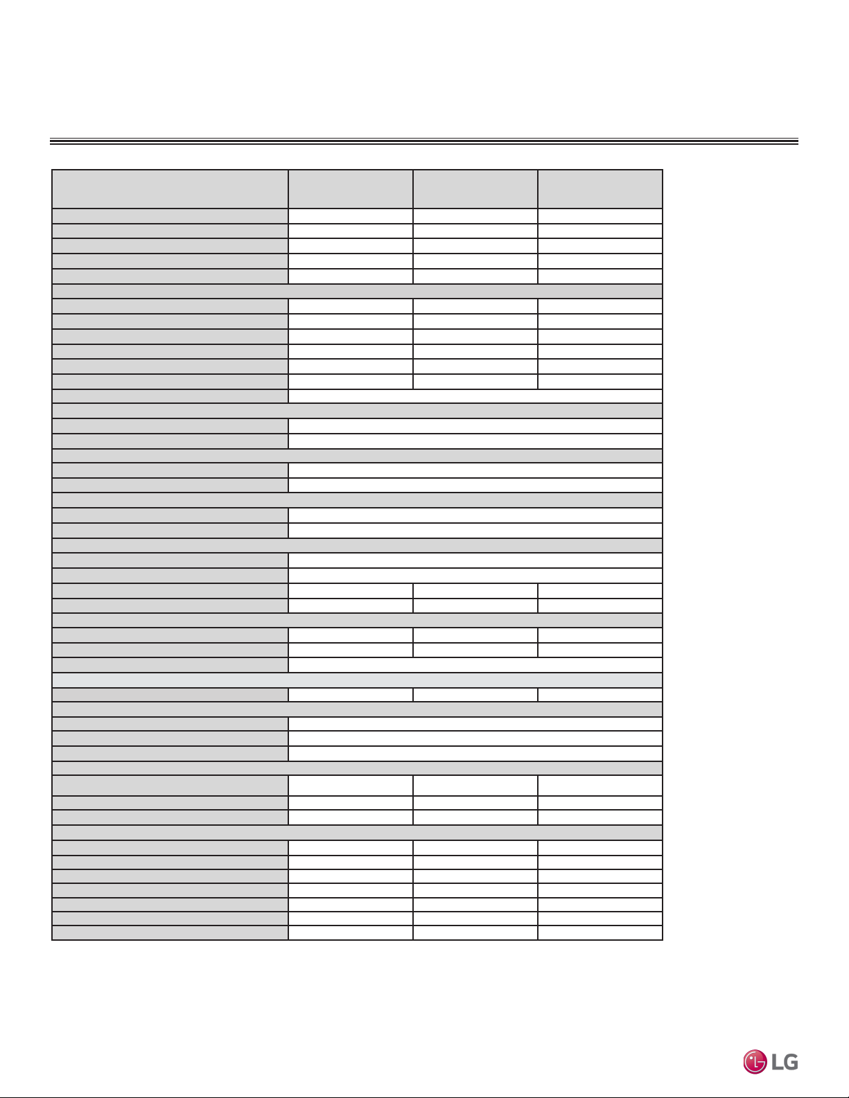
Table 2: Single Zone Art Cool Mirror System Specications.
EEV: Electronic Expansion Valve IDU: Indoor Unit ODU: Outdoor Unit
This unit comes with a dry helium charge.
This data is rated 0 ft above sea level, with 24.6 ft of refrigerant line per indoor unit and a 0 ft level difference between
outdoor and indoor units.
Cooling capacity rating obtained with air entering the indoor coil at 80ºF dry bulb (DB) and 67ºF wet bulb (WB); and
outdoor ambient conditions of 95ºF dry bulb (DB) and 75ºF wet bulb (WB). Heating capacity rating obtained with air
entering the indoor unit at 70ºF dry bulb (DB) and 60ºF wet bulb (WB); and outdoor ambient conditions of 47ºF dry bulb
(DB) and 43ºF wet bulb (WB).
1 Power Input is rated at high speed.
2 Optional low Ambient Wind Baffle Kit allows operation down to 0°F in cooling mode.
3 Take appropriate actions at the end of HVAC equipment life to recover, recycle, reclaim or destroy R410A refrigerant
according to applicable regulations (40 CFR Part 82, Subpart F) under section 608 of CAA.
4 Sound pressure levels are tested in an anechoic chamber under ISO Standard 1996.
5 All communication / connection (power) cable from the outdoor unit to the indoor unit are field supplied and is to be
minimum four-conductor, 14 AWG, stranded, shielded or unshielded (if shielded, it must be grounded to the chassis of the
outdoor unit only), and must comply with applicable local and national codes.
6. Piping lengths are equivalent.
GENERAL DATA
System Model Number (IDU/ODU) LA090HSV5
(LAN090HSV5/
LSU090HSV5
LA120HSV5
(LAN120HSV5/
LSU120HSV5)
LA181HSV5
(LAN181HSV5/
LSU181HSV5)
Cooling Capacity (Min/Rated/Max) (Btu/h) 1,023 ~ 9,000 ~ 12,625 1,023 ~ 12,000~ 13,785 3,070 ~ 18,000 ~ 29,515
Cooling Power Input1(kW) 0.20 ~ 0.62 ~ 0.87 0.20 ~ 0.96 ~ 1.35 0.30 ~ 1.43 ~ 2.00
Heating Capacity (Min/Rated/Max) (Btu/h) 1,023 ~ 10,900 ~ 17,061 1,023 ~ 13,600 ~ 22,178 3,070 ~ 21,600 ~ 38,898
Heating Power Input1(kW) 0.20 ~ 0.71 ~ 1.89 0.20 ~ 1.04 ~ 1.97 0.66 ~ 1.73 ~ 3.98
COP 4.50 3.83 3.66
Maximum Heating Capacity (Btu/h)
Outdoor 17°F (WB)/Indoor 70°F (DB) 11,080 (102%) 13,810 (102%) 22,340 (103%)
Outdoor 5°F (WB)/Indoor 70°F (DB) 9,570 (88%) 11,930 (88%) 19,300 (89%)
Outdoor -4 °F (WB)/Indoor 70°F (DB) 8,310 (76%) 10,360 (76%) 16,760 (77%)
EER2 14.5 12.5 12.55
SEER2 23.2 22.0 22.0
HSPF2 10.2 10.0 9.5
Power Supply (V/Hz/Ø) 208-230 / 60 / 1
Outdoor Unit Operating Range2
Cooling (°F DB) 14 to 118
Heating (°F WB) -4 to 65
Indoor Unit Operating Range
Cooling (°F WB) 53 to 75
Heating (°F DB) 60 to 86
Indoor Temperature Setting Range
Cooling (°F) 64 to 86
Heating (°F) 60 to 86
Unit Data
Refrigerant Type3R410A
Refrigerant Control EEV
IDU Sound Pressure4dB(A) (H/M/L/Sleep) 41 / 35 / 25 / 21 41 / 35 / 25 / 21 47 / 42 / 37 / 31
ODU Sound Pressure4dB(A) (Cool/Heat) 47 / 51 47 / 51 55 / 55
Unit Weight (lbs)
IDU (Net/Shipping) 20.5 / 25.6 20.5 / 25.6 29.8 / 36.4
ODU (Net/Shipping) 74.1 / 78.9 74.1 / 78.9 127.9 / 145.5
Power/Communication Cable5 (No. x AWG) 4 x 14
Compressor
Compressor Type (Qty) Twin Rotary (1) Twin Rotary (1) Twin Rotary (1)
Fan
IDU Type (Qty) Cross Flow (1)
ODU Type (Qty) Propeller (1)
Motor/Drive Brushless Digitally Controlled/Direct
Airflow Rate
IDU Cooling (Max /H /M /L [CFM]) 459 / 338 / 317 / 194 459 / 338 / 317 / 194 706 / 530 / 477 / 371
IDU Heating (Max /H /M /L [CFM]) 459 / 338 / 317 / 229 459 / 338 / 317 / 229 706 / 547 / 494 / 371
ODU Max (CFM) 1,165 1,165 2,119
Piping
Liquid Line (in, OD) ø1/4 ø1/4 ø3/8
Vapor Line (in, OD) ø3/8 ø3/8 ø5/8
Condensation Line (OD, ID) 27/32, 5/8 27/32, 5/8 27/32, 5/8
Additional Refrigerant Charge (oz/ft) 0.22 0.22 0.38
Pipe Length6(Min./Std./Max.) (ft.) 9.8 / 24.6 / 82 9.8 / 24.6 / 82 9.8 / 24.6 / 114.8
Piping Length6(no add’l refrigerant, ft) 41.0 41.0 24.6
Max Elevation Difference (ft) 49.2 49.2 49.2

Due to our policy of continuous product innovation, some specications may change without notication.
©LG Electronics U.S.A., Inc., Englewood Cliffs, NJ. All rights reserved. “LG” is a registered trademark of LG Corp.
PRODUCT DATA | 11
Product Data
Table 3: Single Zone Art Cool Mirror Wall Mount Electrical Data.
Electrical Data
ELECTRICAL DATA
Indoor Unit Outdoor Unit Hertz Voltage
Voltage
Range
(Min. to
Max.)
MCA MOP
Com-
pressor
Quantity
LRA
Compressor Motor
RLA
Outdoor Fan
Motor
Indoor Fan
Motor
Cooling Heating W FLA W FLA
LAN090HSV5 LSU090HSV5
60 208 - 230 187 - 253
10.0 15.0 1 7.5 7.0 7.0 43 0.4 30 0.4
LAN120HSV5 LSU120HSV5 10.0 15.0 1 7.5 7.0 7.0 43 0.4 30 0.4
LAN181HSV5 LSU181HSV5 19.0 30.0 1 17.0 12.6 14.3 124 0.78 70 0.4
Voltage tolerance is ±10%.
Maximum allowable voltage unbalance is 2%.
MCA = Minimum Circuit Ampacity.
Maximum Overcurrent Protection (MOP) is calculated as
follows: (Largest motor FLA x 2.25) + (Sum of other motor
FLA) rounded down to the nearest standard fuse size.
RLA = Rated Load Amps.
FLA = Full Load Amps.
W: Fan Motor Rated Output (W)
LRA = Locked Rotor Amps

Due to our policy of continuous product innovation, some specications may change without notication.
©LG Electronics U.S.A., Inc., Englewood Cliffs, NJ. All rights reserved. “LG” is a registered trademark of LG Corp.
12 |PRODUCT DATA
Single Zone Art CoolTM Mirror Wall Mount Engineering Manual
Table 4: Indoor Unit—Functions, Controls and Options.
FUNCTIONS, CONTROLS, AND OPTIONS
Indoor Unit
Indoor Unit Type LA090HSV5 LA120HSV5 LA181HSV5
Airow
Air Supply Outlet 1 1 1
Airflow Direction Control (Left / Right) 5 Steps 5 Steps 5 Steps
Airflow Direction Control (Up / Down) 6 Steps 6 Steps 6 Steps
Auto Swing (Left / Right) √ √ √
Auto Swing (Up / Down) √ √ √
Fan Speed Airflow Steps (Fan / Cool / Heat) 6 / 6 / 6 6 / 6 / 6 6 / 6 / 6
Natural Wind (Auto Wind) √ √ √
Jet Cool / Jet Heat (Power Wind) √ / √ √ / √ √ / √
Comfort Air √ √ √
Air
Purifying
Prefilter (Washable / Anti-fungal1)√ √ √
3M Micro Dust Filter √ √ √
Functions
Hot Start √ √ √
Self Diagnostics √ √ √
Defrost √ √ √
Dry (Dehumidification) Operation √ √ √
Auto Changeover √ √ √
Auto Cleaning (Coil Dry) √ √ √
Auto Restart Operation √ √ √
Child Lock1√ √ √
Forced Operation √ √ √
Sleep Mode 7 Hour 7 Hour 7 Hour
Timer (24 Hour On / Off) √ √ √
Weekly Timer1√ √ √
Two Thermistor Control1√ √ √
Low Ambient Operation √ √ √
Overheat Protection √ √ √
Smart Diagnosis √ √ √
Indoor Unit Display Type Number Display Number Display Number Display
Indoor Unit Display Light On / Off On / Off On / Off
Energy Saving √ √ √
Mode Lock Cooling Only Cooling Only Cooling Only
Central
Controllers
AC Smart IV PACS4B000 PACS4B000 PACS4B000
ACP IV PACP4B000 PACP4B000 PACP4B000
PI-485 PMNFP14A1 PMNFP14A1 PMNFP14A1
Remote
Controllers
MultiSITE™CRC1 PREMTBVC0 PREMTBVC0 PREMTBVC0
MultiSITE CRC1+ PREMTBVC1 PREMTBVC1 PREMTBVC1
Integration
Solution
MultiSITE Communications Manager PBACNBTR0A PBACNBTR0A PBACNBTR0A
Building
Network
Unit
LonWorks® Gateway PLNWKB100 PLNWKB100 PLNWKB100
AC Smart IV BACnet® Gateway PBACNA000 PBACNA000 PBACNA000
ACP IV BACnet Gateway PQNFB17C2 PQNFB17C2 PQNFB17C2
Other
Dry Contact PDRYCB100, PDRYCB320, PDRYCB400
Wind Baffle Kit ZLABGP01A ZLABGP01A ZLABGP04A
Wi-Fi2√ √ √
Water Level Sensor Connection (for optional AG-9300-LG) √ √ √
Base Pan Heater √ √ √
Smart Inverter Monitoring System (SIMS) √ √ √
√ = Standard feature
X = Not available
¹Function can operate only when a wired remote controller is connected.
2Wi-Fi is only compatible with 2.4 GHz band, and cannot be used when dry contact mode is active. When changing from Wi-Fi mode to dry contact mode,
normal operation resumes in approximately 3 minutes.
LonWorks® is a trademark of Echelon Corporation; BACnet® is a registered trademark of ASHRAE.

Due to our policy of continuous product innovation, some specications may change without notication.
©LG Electronics U.S.A., Inc., Englewood Cliffs, NJ. All rights reserved. “LG” is a registered trademark of LG Corp.
PRODUCT DATA | 13
Product Data
INDOOR UNIT DIMENSIONS
Dimensions for LAN090HSV5, LAN120HSV5
Figure 4: LAN090HSV5 LAN120HSV5 Unit Dimensions.
Unit : inch (mm)
[30-3/16 (767)]
32-15/16 (837)
3-5/8 (92)
2-3/8 (60)
2-5/16
(59)
12-1/8 (308)
7-9/16 (192)
32-15/16 (837)
1-1/2 (38)
Approx. 8-19/32 (218) to liquid pipe
Approx. 11-11/32 (288) to gas pipe
1-27/32(47)
5-3/16 (132)
In Case of Left Side Piping
Unit Outline
Connecting Gas/Liquid Pipe
12-1/8 (308)
2-7/32(56)
11/32 (9)
5/16 (8)
2 (51)
Air Intake
Air Outlet
Bottom
[28-5/32 (715)]
Air Outlet Hole
* If airflow direction control is available,
Cooling Heating
Up & Down Left & Right
Air Outlet Hole
Air Intake Hole
[5-29/32 (150)]
Air Intake Hole
Rear Rear
Right
Left
55°
15° 15°
85°
45°
55°
32-15/16 (837)
2-15/32
(63)
12-1/16 (306)
3-21/32 (93)
10-11/32 (263)
5-31/32 (152)
3-27/32 (98)
5-9/32 (134)
12-1/8 (308)
3-11/16 (94)
7-5/8 (194)
Unit Outline
Fixing the Installation Plate, Drilling Hole
29/32 (23)
Ø2-9/16 (65)
1-3/32 (50.2) 1-1/16 (26.2)
5-31/32 (152) 2-7/32 (56)
2 (51)
2-7/32 (56)
Ø2-9/16 (65)
29/32 (23)
2-15/32 (63)
2-17/32 (64)
7-27/32 (199)7-27/32 (199)5-19/32 (142)
5-19/32 (142)
Decoration Cover
Terminal Block for
Power Supply and
Communication
Display & Remote
Controller Signal
Receiver Signal
Refrigerant, Drain
Pipe, and Cable
Knock Out Hole
Installation Plate
Drain Hose
Connection
Refrigerant, Drain
Pipe and Cable
Knock Out Hole
Refrigerant,
Drain Pipe
and Cable
Knock
Out Hole
2-7/16 ( 61.5)
1-9/32 (32.7)
2-13/32 (61)
1/4 (6) x 1/8 (3)
1/8 (3) x 1/4 (6)
5/8 (15.3)
1-1/4 (31)
1-7/16 (33.5)

Due to our policy of continuous product innovation, some specications may change without notication.
©LG Electronics U.S.A., Inc., Englewood Cliffs, NJ. All rights reserved. “LG” is a registered trademark of LG Corp.
14 |PRODUCT DATA
Single Zone Art CoolTM Mirror Wall Mount Engineering Manual
INDOOR UNIT DIMENSIONS
Dimensions for LAN181HSV5
Figure 5: LAN181HSV5 Unit Dimensions.
Unit : inch (mm)
[36-5/32 (918)]
Air Intake Hole
[6-11/16 (170)]
Air Intake Hole
ir Outlet Ho
[2-29/32 (74)]
Rear
A le
39-9/32 (998)
2-1/4 (57)
2-7/32 (56)
3-17/32 (90)
Bottom Air
Outlet
[34-11/32 (872)]
Air Outlet Hole
13-19/32 (345)
2-3/8 (60)
7/16(11)
Air Intake
8-11/32 (212)
13-19/32 (345)
39-9/32 (998)
6-15/32 (164)
1-15/32 (37)
2-15/32 (63)
In case of Left Side Piping
Unit Outline
Approx. 9-7/16 (240) to gas pipe
Approx. 6-5/16 (160) to liquid pipe
Connecting Gas/Liquid Pipe
2-3/8 (60)
2-3/8 (60)
Rear
Left Right
If airflow direction control is available,*
Cooling Heating
Up & Down Left & Right
50°
15°
20°
85°
45°
50°
39-9/32 (998)
2-23/32 (69)
14-11/16 (373)
5-13/32 (137)
2-3/32 (53)
13-19/32 (345)
Ø2-9/16 (65)
3-9/32 (83)
1-1/16 (27)
Unit Outline
Fixing the Installation Plate, Drilling Hole
5-29/32 (150)
4-17/32 (115)
Ø2-9/16 (65)
3-9/32 (83)
5-9/32 (134)
1-1/16 (27)
2-3/32 (53)
11-13/16 (300)
7/16 (11)
1-3/32 (50.2) 1-1/16 (26.2)
5-31/32 (152)
2-3/8 (60)
5-29/32 (150)5-29/32 (150)
7-13/32 (188)
7-13/32 (188)
Terminal Block for
Power Supply and
Communication
Refrigerant, Drain
Pipe and Cable
Knock Out Hole
Refrigerant, Drain
Pipe, and Cable
Knock Out Hole
Display & Remote
Controller Signal
Receiver Signal
Decoration Cover
Refrigerant,
Drain Pipe
and Cable
Knock
Out Hole
Drain Hose Connection
Installation Plate
2-7/16 ( 61.5)
1-9/32 (32.7)
2-13/32 (61)
1/4 (6) x 1/8 (3)
1/8 (3) x 1/4 (6)
5/8 (15.3)
1-1/4 (31)
1-7/16 (33.5)

Due to our policy of continuous product innovation, some specications may change without notication.
©LG Electronics U.S.A., Inc., Englewood Cliffs, NJ. All rights reserved. “LG” is a registered trademark of LG Corp.
PRODUCT DATA | 15
Product Data
OUTDOOR UNIT DIMENSIONS
Figure 6: LSU090HSV5, LSU120HSV5 Outdoor Unit Dimensions.
Dimensions for LSU090HSV5, LSU120HSV5
Unit : Inch (mm)
4-3/16 (106)
31/32 (24)
10-1/2(267)
19/32 (15)
21-1/2 (545)
4-15/16 (125)
6-7/16 (163)
5-3/32 (129)
1-7/32 (30.5)
12-1/16 (306)
9-5/16 (236)
30-5/16 (770)
10-29/32 (277)
Ø17-11/32 (440)
2-23/32 (69)
15/32 (11.5)
11-5/16 (288)
13/16 (20)
25°
25°
2-3/32 (54)
22 (558)
12-31/32 (330)
13-29/32 (353)
Drain Hole 8-Ø13/16 (20)
Liquid Pipe
Connection
(Flared)
Vapor Pipe
Connection
(Flared)
Sump Heater
Service Valve Cover
Communication /
Connection
(Power)
Cable Hole
Control Box
Air Outlet

Due to our policy of continuous product innovation, some specications may change without notication.
©LG Electronics U.S.A., Inc., Englewood Cliffs, NJ. All rights reserved. “LG” is a registered trademark of LG Corp.
16 |PRODUCT DATA
Single Zone Art CoolTM Mirror Wall Mount Engineering Manual
OUTDOOR UNIT DIMENSIONS
Figure 7: LSU181HSV5 Outdoor Unit Dimensions.
Dimensions for LSU181HSV5
Unit : inch (mm)

Due to our policy of continuous product innovation, some specications may change without notication.
©LG Electronics U.S.A., Inc., Englewood Cliffs, NJ. All rights reserved. “LG” is a registered trademark of LG Corp.
PRODUCT DATA | 17
Product Data
OUTDOOR UNIT CORNER WEIGHT AND
CENTER OF GRAVITY DIMENSIONS
Figure 8: LSU090-120-181HSV5 Outdoor Unit Corner Weight and Center of Gravity Dimensions.
Model No. Weight (lb.) Center of Gravity (in.) Leg (in.) Corner Weight (lb.)
Shipping Net a b c d e A B C D
LSU090HSV5,
LSU120HSV5 78.9 74.1 19-31/32 9-11/32 5-21/32 22 12-31/32 9.5 11.0 26.8 26.8
LSU181HSV5 145.5 127.9 23-7/32 12-19/32 5-29/32 24-13/32 14-3/16 18.6 24.2 49.1 43.5
Table 5: LSU090-120-181HSV5 Outdoor Unit Corner Weight and Center of Gravity Dimensions.
d
e
a
b
c
AD
BC

Due to our policy of continuous product innovation, some specications may change without notication.
©LG Electronics U.S.A., Inc., Englewood Cliffs, NJ. All rights reserved. “LG” is a registered trademark of LG Corp.
18 |PRODUCT DATA
Single Zone Art CoolTM Mirror Wall Mount Engineering Manual
ACOUSTIC DATA
Indoor Units
Indoor Unit Sound Pressure Levels
Indoor Unit Sound Pressure Measurement
Model
Sound Pressure Levels (dB[A])
Cooling Heating
H M L H M L
LAN090HSV5 41 35 25 41 35 26
LAN120HSV5 41 35 25 41 35 26
LAN181HSV5 47 42 37 47 42 37
Table 6: Art Cool Mirror Indoor Unit Acoustic Data
Figure 9: Art Cool Mirror Indoor Unit Sound Level Measurement.
• Measurements are taken 3.3 ft away from the front of the unit.
• Sound pressure levels are measured in dB(A) with a tolerance of
±1.
• Data is valid at nominal operation conditions. Operating conditions
are assumed to be standard.
• Reference acoustic pressure 0dB=20μPa
• Sound pressure levels are tested in an anechoic chamber under
ISO Standard 3745, and may be different according to the test
condition or equipment.
• Sound level will vary depending on a range of factors including the
construction (acoustic absorption coefficient) of a particular room in
which the unit was installed.
2.6 (0.8)
3.3 (1)
Microphone
Unit : ft. (m)
Figure 10: LAN090/120HSV5 Cooling Sound Pressure Level Diagram. Figure 11: LAN090/120HSV5 Heating Sound Pressure Level Diagram.
LAN090HSV5/LAN120HSV5 Cooling and Heating Sound Pressure Diagrams

Due to our policy of continuous product innovation, some specications may change without notication.
©LG Electronics U.S.A., Inc., Englewood Cliffs, NJ. All rights reserved. “LG” is a registered trademark of LG Corp.
PRODUCT DATA | 19
Product Data
ACOUSTIC DATA
Indoor Units
Figure 12: LAN181HSV5 Cooling Sound Pressure Level Diagram.
LAN181HSV5 Cooling and Heating Sound Pressure Diagrams
Figure 13: LAN181HSV5 Heating Sound Pressure Level Diagram.

Due to our policy of continuous product innovation, some specications may change without notication.
©LG Electronics U.S.A., Inc., Englewood Cliffs, NJ. All rights reserved. “LG” is a registered trademark of LG Corp.
20 |PRODUCT DATA
Single Zone Art CoolTM Mirror Wall Mount Engineering Manual
Model Sound Pressure Levels (dB[A])
Cooling (Max) Heating (Max.)
LSU090HSV5 47 51
LSU120HSV5 47 51
LSU181HSV5 55 55
Table 7: Art Cool Mirror Outdoor Unit Acoustic Data
Figure 14: Outdoor Unit Sound Level Measurement.
Outdoor Unit Sound Pressure Level Measurement
Outdoor Unit Sound Pressure Levels
ACOUSTIC DATA
Outdoor Units
• Measurements are taken 3.3 ft away from the front of the unit.
• Sound pressure levels are measured in dB(A) with a tolerance of ±1.
• Data is valid at nominal operation conditions. Operating conditions
are assumed to be standard.
• Reference acoustic pressure 0dB=20μPa
• Sound pressure levels are tested in an anechoic chamber under ISO
Standard 3745, and may be different according to the test condition
or equipment.
• Sound level will vary depending on a range of factors including the
construction (acoustic absorption coefficient) of a particular room in
which the unit was installed.
Figure 15: LSU090/120HSV5 Cooling Sound Pressure Level Diagram. Figure 16: LSU090/120HSV5 Heating Sound Pressure Level Diagram.
LSU090HSV5/ LSU120HSV5 Cooling and Heating Sound Pressure Diagrams
3.3 ft. (1)
Center of
Outdoor Unit
Unit : ft. (m)
This manual suits for next models
8
Table of contents
Other LG Air Conditioner manuals
Popular Air Conditioner manuals by other brands

Daikin
Daikin EWAQ004BAVP Installer's reference guide

Retro Aire
Retro Aire R30C Installation, operation & maintenance manual

Mitsubishi Electric
Mitsubishi Electric PUHZ-RP50VHA4 Service manual

Daikin
Daikin FFQ09Q2VJU Operation manual

NEC
NEC RIH-6867 user manual

Frigidaire
Frigidaire FAZ12ES2A installation instructions

PR KLIMA
PR KLIMA GPC10AL operating instructions

hawa
hawa 3122 Series operating instructions

Hitachi
Hitachi RAS-10NHZ4(H) instruction manual

Mitsubishi Electric
Mitsubishi Electric MSZ-FA25VA Service manual

nedis
nedis ACMB1WT9 quick start guide

Mars
Mars COMFORT-AIRE PS-81G Owner's manual & installation manual