SeeEyes SC-04MHD User manual

Release Version 2.0
4CHANNEL VIDEO INPUT DIGITAL SPLITTER
SC-04MHD
User's Manual

Release Version 2.0
1
The content of this guideline is to protect the safety of users and prevent property damage.
Be sure to read this user’s manual thoroughly and use the device correctly.
Warning (If you do not keep any of the below guidelines, you may get seriously injured
or cause somebody’s death.)
■Be sure to install the product after unplugging power cord. Also, do not use many power
plugs at the same time.
- It may cause abnormal heat, fire and electric shock.
■Do not leave the device at any place that water falls or splashes. Also, do not put anything
full of water such as a flower vase on the device.
- It may cause malfunction or fire if liquid go into the device.
■Do not bend the power cord by excessive force. Make sure the power cord is not crushed by
heavy things.
- It may cause fire.
■Do not open the lid arbitrarily as this device has high voltage part inside. Never disassemble,
repair or modify it.
- By abnormal working, it may cause fire, electric shock and personal injury.
■Do not install this product in places with high humidity, dust, or soot.
- It may cause electric shock and fire.
■Do not tug at the power cord section or unplug the power plug with wet hands. If the power
cord is loose, do not plug in.
- There may be a risk of fire and electric shock.
■Keep the device in a cool place where doesn’t let direct sunlight. Keep it at a proper
temperature and avoid heating appliances like candle or heater. Also, keep the equipment or
tools away from places where people come and go.
- It may cause fire.
■Pay attention to possible hazards in the workplace, such as wet floor, ungrounded power
extension cables, old power cords and a lack of safety earth. Consult your place of purchase or
professional if problems arise.
- It may cause fire and electric shock.
■Keep the back of the product more than 15cm and the sides more than 5cm from the wall. If
you install the product too close to the wall, it can cause the cable to be bend, compressed too
hard or break, as various external input/ouput ports such as power cords protrude from the
back of the product.
- It may cause fire, electric shock and personal injury.
■Concerning the input voltage for operating this device, a voltage range must be within 10%
of rated voltage, and the power outlet must be grounded. Also, do not use a heat source such
as a hair dryer, iron and refrigerator to the same power unit.
- It may cause abnormal heat, fire and electric shock.
Precaution and Safety Guidelines

Release Version 2.0
2
Caution (If you do not keep any of the below guidelines, you may get injured or suffer
property loss.)
■Avoid installation in areas with strong magnetic fields or near wireless devices such as radio
or TV.
- Install the device in a place free from magnetic particles, radio waves or severe vibration.
■Proper ambient temperature and humidity are recommended.
- Avoid extremely high temperatures(over 50°C) or low(below -10°C), and humid conditions.
■Do not place heavy items on the product or let foreign substances enter inside the device.
- It may cause failure.
■Install in well ventilated place, and avoid direct sunlight or heat appliance.
■Install at a flat and stable place. Do not use an upright or slanted position.
- It may not operate properly or might be dangerous due to the fall of the device.
■Strong shock or vibration may cause device failure. Be careful when using the device.
- Install in a place without severe vibration.
■If you notice any unusual noise or smell, unplug the power supply immediately and contact
the place of purchase or service center.
- There may be a risk of fire and electric shock.
■Rotate the air properly in the system operating room and secure the cover of the main body.
- It may be the cause of failure by environmental factors.
■Refer the device to the service center and get regular checkup to maintain the performance
of the system.
- We are not responsible for any damages caused by user’s carelessness.
■Make sure to plug the power cord with grounded outlet.
- There is a risk of electrical shock and personal injury.
■Place the power plug in a location that is easy to operate.
- If a failure of the product occurred, the power plug must be unplugged to power down completely.
The power button on the main unit does not completely turn off the power.
■Transmission distance may vary depending on the type of coaxial cable.
■Do not use this device in close proximity to a device that produces strong waves such as
radio set(TRANCEIVER, Walkie-talkie, etc.) or repeater. It may affect the video signal, or cause
disorders such as noise or crack on the screen.
■Disconnect the power plug with care during thunder and lightning.
■Refer to the user’s manual for problems or questions besides the above. Contact our service
center if you need assistance from a professional technician.
■To extend or terminate the coaxial cables, you should connect them in the following way.
- BNC-M(Male) - BNC-JJ - BNC-M(Male): BNC Connector Connection Example
■Make the joint part of the cables insulated completely not to expose the metal parts.

Release Version 2.0
3
1. Introduction
1-1. Overview
SC-04MHD is a 4 channel multi-format video digital splitter, which provides high-resolution display in
various split modes in real time.
This item supports various input such as AHD, TVI, CVI, CVBS and has various output ports to be
compatible with many different external devices. Also, remote control operation is available through
the RS-485 port. It displays the date, time and the name of channel on the monitor as well as any
channel loss.
1-2. Features
•Various video input (AHD, TVI, CVI, CVBS)
•Support Loop through output
•Display video of four cameras in real time
•Various split mode: 2 split, 4 split or 3 split screen
•Auto sequence function
•RS-485 communication port for a remote control
•Alarm port: 4 Input, 1 Output (Relay Contact)
•Display and save the date and time when alarm and loss are generated
•Various video output resolution
HDMI: 1920x1080p 25/30/50/60Hz, 1920x1080i 50/60Hz, 1280x720p 50/60Hz,
1024x768@60Hz, 1360x768@60Hz, 1600x1200@60Hz
VGA: 1920x1080p 60Hz, 1280x720p 60Hz, 1024x768@60Hz, 1360x768@60Hz, 1600x1200@60Hz
CVBS: NTSC, PAL
2. Components
SC-04MHD
Adapter
(DC12V)
HDMI Cable
Rubber Feet
& Screws
Rack Brackets
& Screws
User’s
Manual

Release Version 2.0
4
3. Product Parts and Peripheral Device Connection
3-1. Front Interface
①POWER: To turn the power on/off.
②MENU: To set up this item and/or check the current settings.
③DUAL: To turn to the horizontal/vertical 2-split screen mode.
The green LED will be on when pressing this button in split mode.
In the menu, it is possible to enter the sub-menu or save the settings via this button.
Split Mode
Split Screen
Vertical 2-split
mode
Horizontal 2-split
mode
①②③④⑤⑧⑥⑦⑨

Release Version 2.0
5
④AUTO: To enable auto sequence mode.
Once you press this button in the split mode for a second, the green LED will be on, the video will be
displayed from 1CH to 4CH in full screen successively.
Once you press this button for a few seconds in the cropping mode of a vertically two-split mode,
the LED will be flickering and a red circle will be shown in the relevant channel. After then, you can
shift the relevant video to another position by using the up/down/left/right keys and save it by
pressing this button for a few seconds again.
Once you press this button in the auto sequence mode again, the green LED will be off and the auto
sequence mode will be terminated. In the menu. It is possible to enter the upper menu or cancel the
settings via this button.
Split Mode
Split Screen
Auto Sequence
⑤QUAD: To turn to the horizontal/vertical 4-split (quad) screen mode.
The green LED will be on when pressing this button in the split mode.
Split Mode
Split Screen
Vertical 4-split
mode
Horizontal 4-split
mode
Vertical 3-split
mode
⑥SINGLE DISPLAY 1: To display the channel 1 in full screen and select a channel to crop in general.
To move to the top in the menu mode.
⑦SINGLE DISPLAY 2: To display the channel 2 in full screen and shift the cropped image in general.
To move to the right in the menu mode.
⑧SINGLE DISPLAY 3: To display the channel 3 in full screen and select a channel to crop in general.
To move to the bottom in the menu mode.
⑨SINGLE DISPLAY 4: To display the channel 4 in full screen and shift the cropped image in general.
To move to the left in the menu mode.
※If the signal type of input video is both NTSC(30fps) and PAL(25fps), it is recommended to
use the same kind of video because NTSC images on the split screen may be unnatural.
※How to use the CROPPING function (VIDEO SCALE 16:9)
The cropping function enables in the vertical 2-split modes only. Press the DUAL key to display the
video in 16:9 (or 4:3, Full) and press the key again to display the center image and “CROPPING
MODE” message in the center (This message will disappear within three seconds).

Release Version 2.0
6
1) Vertical 2 Split
Press the AUTO KEY for a few seconds to make the AUTO KEY LED flickering and a red line displayed.
Press the SINGLE DISPLAY 3 to shift the image on the right side and press SINGLE DISPLAY 1 to
shift the image on the left side.
Press the SINGLE DISPLAY 2 to shift the image to the right and press the SINGLE DISPLAY 4 to shift
the image to the left during the red line is activated.
(CROPPING MODE) (SINGLE DISPLAY 2 KEY) (SINGLE DISPLAY 4 KEY)
Press the AUTO KEY for a few seconds to terminate the cropping mode by making the red line
disappear and the AUTO KEY LED off.
2) Horizontal 2 Split
Press the AUTO KEY for a few seconds to make the AUTO KEY LED flicker and a red line is displayed.
Press the SINGLE DISPLAY 3 to select the image at the bottom, and press SINGLE DISPLAY 1 to
shift the red line to select the image at the top.
Press the SINGLE DISPLAY 2 to shift image to the bottom, and press the SINGLE DISPLAY 4 to shift
the image to the top during the red line is activated.
(CROPPING MODE) (SINGLE DISPLAY 2 KEY) (SINGLE DISPLAY 4 KEY)
Press the AUTO KEY for a few seconds to terminate the cropping mode by making the red line
disappear and the AUTO KEY LED off.
※Not to change the channel to any channel having alarm or video loss from the cropped
image, please turn off the ALARM I/O and LOSS in the MENU SYSTEM.

Release Version 2.0
7
3-2. Backside Interface
①VIDEO INPUT:HD Analog (AHD, TVI, CVI) and CVBS video input (up to four channels).
②CVBS: CVBS video output.
③VGA OUT: RGB output.
④ALARM INPUT: Alarm input to control the video display screen by a foreign sensor or switch
connected.
Display Mode per Foreign Alarm Input
Foreign Input
Display Mode
IN 1
IN 2
IN 3
IN 4
0
0
0
0
Normal Mode
1
0
0
0
CH 1 Full Display
0
1
0
0
CH 2 Full Display
0
0
1
0
CH 3 Full Display
0
0
0
1
CH 4 Full Display
For more than a channel input
4 Splitter Display
※When alarm is entered in a specific channel, the relevant video channel will be displayed.
※Input OFF mode =”0”, Input ON mode =”1” (The GND and the Inx produce a short circuit)
※The relevant video channel will not be displayed when the alarm signal is entered into a channel
having signal attenuation.
④-①Alarm Input
The GND and the Inx open or produce a short circuit by using a contact signal (switch, relay) that
does not receive electric signal. When an alarm is produced by a foreign alarm input, the relevant
channel will be displayed. When pressing other buttons during the Alarm Hold time, the alarm will be
cleared.
④-②Alarm Clearance
When the external control data (alarm input) is eliminated, it returns to the last display mode
which had been displayed before the external data has entered after the Alarm Hold time. You can
set the Alarm Hold time as following steps: SETUP MENU →SYSTEM MENU →ALARM HOLD.
①
②
③
④
⑤
⑥
⑦
⑧
⑨
⑩
⑪
⑫

Release Version 2.0
8
④-③Alarm Operation Structure
⑤POWER: DC 12V/200mA output.
⑥RS-485: RS-485 communication by an external device for a remote control.
⑥-①Communication Settings
- Data Length: 8 Bit, Start/Stop Bit: 1Bit, Parity Bit: None, Baud Rate: menu set point.
- Control Communication Data Format
Byte
Value
Function
1
0xA0
STX (Launching data)
2
0x16
Device Code: Product identification code
3
0x01 ~ 0xFF
Address (Device ID)
4
Data Byte
Control Data
5
Check Sum
Check Sum = Byte2 + Byte3 + Byte4
⑥-②Control Data Code
Hex
Function
Remark
Packet
0x34
CH 01 Full Display, UP
(Cropping Channel Selection/ Left, up Screen)
Screen, Menu
0xA0 0x16 0x01 0x34 0x4b
0x35
CH 02 Full Display, RIGHT
(Cropping Channel Position/ Shift to the right, up)
Screen, Menu
0xA0 0x16 0x01 0x35 0x4c
0x36
CH 03 Full Display, DOWN
(Cropping Channel Selection/ Right, down Screen)
Screen, Menu
0xA0 0x16 0x01 0x36 0x4d
0x37
CH 04 Full Display, LEFT
(Cropping Channel Position/ Shirt to the left, down)
Screen, Menu
0xA0 0x16 0x01 0x37 0x4e
0x47
Dual Display, ENTER
2-split, Menu
0xA0 0x16 0x01 0x47 0x5e
0x48
Menu
Menu
0xA0 0x16 0x01 0x48 0x5f
0x50
Quad Display
4-split
0xA0 0x16 0x01 0x50 0x67
0x5A
Auto Sequence, PREV.
Screen, Menu
0xA0 0x16 0x01 0x5a 0x71
0x5B
Cropping Mode
Cropping
0xA0 0x16 0x01 0x5b 0x72
Release Version 2.0
9
⑦DC IN: Power input.
⑧VIDEO OUTPUT: HD-Analog and CVBS video output.
※When connecting it to the BNC port, 75Ωtermination will be released as there is the auto
termination switch inside. Therefore, if you do not connect it to an external device such as a DVR
after connecting it to the BNC port, the displayed image may blur due to the termination problem.
⑨HDMI: HDMI output.
⑩MINI-USB: To update the firmware.
⑪GND (Ground): Alarm input and power output. To control the product by an external device.
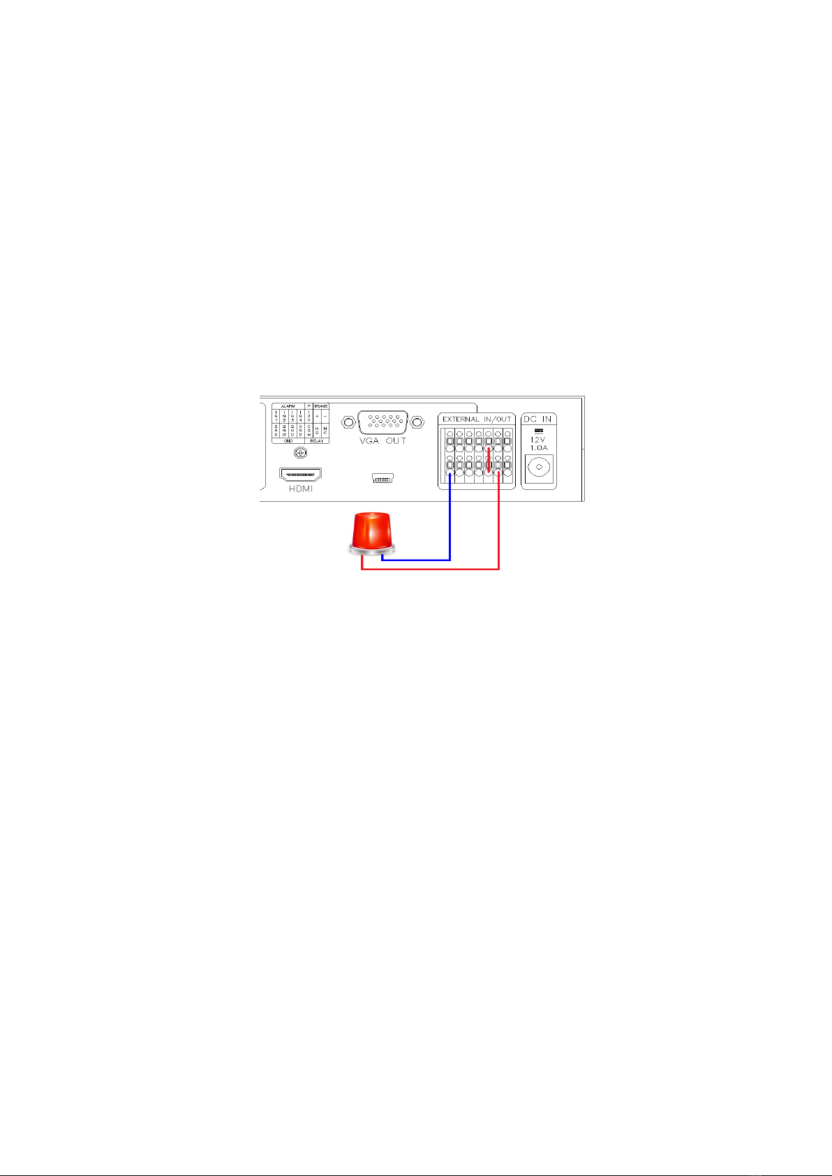
⑫RELAY: Electric signal output.
To operate a light or an emergency bell by using electric signal when any alarm occurs.
N.O (Normal Open): the contact point is off.
N.C (Normal Close): the contact point is on.
ALARM Output Example

Release Version 2.0
10
4. Menu Setup
MENU Structure
SYSTEM
INPUT
OUTPUT
DISPLAY
DATE/TIME
CH TITLE
EVENT
•SYSTEM ID
•BAUDRATE
•ALARM I/O
•ALARM HOLD
•BUZZER OUT
•BUZZER TIME
•LOSS
•EVENT SAVE
•EVENT CLEAR
•UTC CONTROL
•DEFAULT ALL
•CH1
•CH2
•CH3
•CH4
•HDMI/VGA
•CVBS
•CH INFO. BOX
•CH TITLE
•CH TITLE POS.
•CH TITLE SIZE
•DATE & TIME
•BORDER LINE
•SEQUENCE TIME
•DE-INTER MODE
•VIDEO SCALE
•DATE FORMAT
•LOCATION
•DATE SET
•TIME SET
•CH01
•CH02
•CH03
•CH04
NO. YY/MM/DD HH:NN:SS EVT CH
4-1. Start-up Screen of the Menu
- Press the menu button on the front side of SC-04MHD to display the menu as shown
above.
- Move the sub-menus by using the △▽ buttons and press the DUAL(Select) button to
select one of the sub-menus.
- To enter the setup screen, please press the menu button when the above image is
displayed.
- Use the △▽ buttons to select the sub-items in each setup menu and change the setting
values by ◁▷ buttons.
- Press AUTO button to return to the menu from the sub-menu.
Release Version 2.0
11
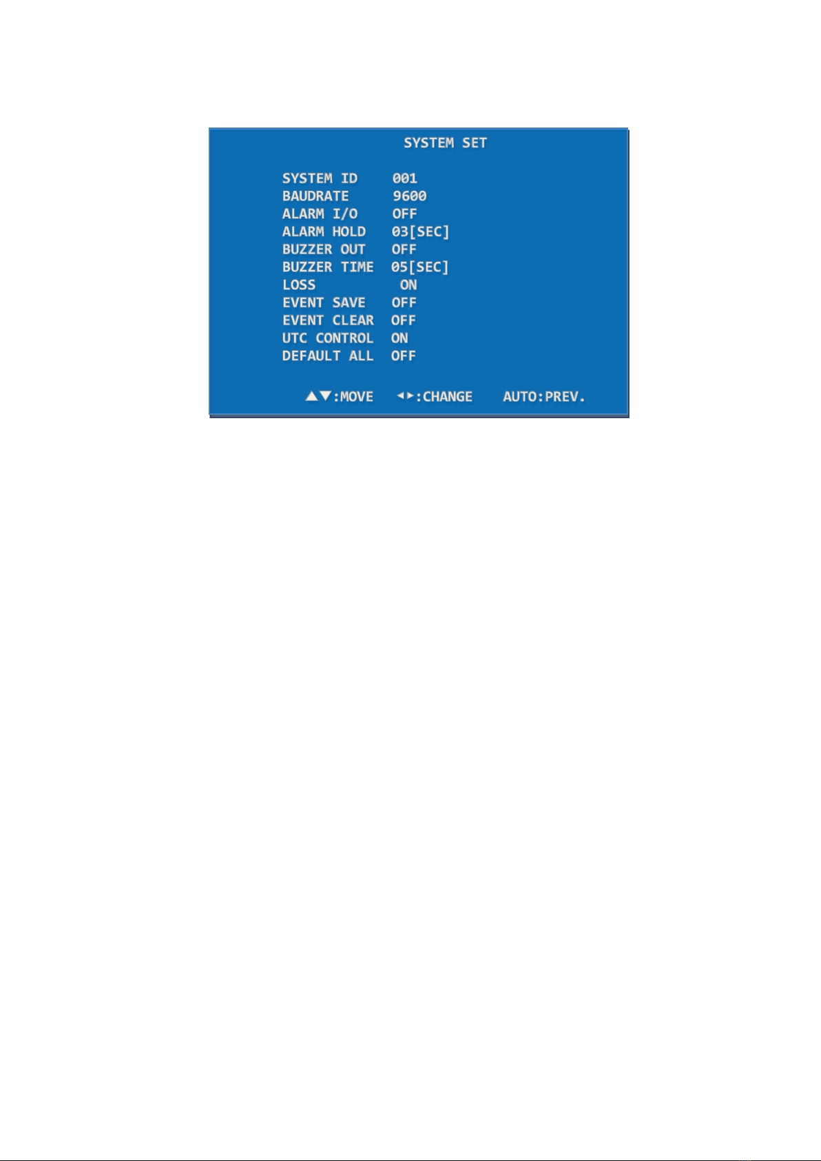
4-2. SYSTEM Setup
4-2-1. SYSTEM ID
Use the system ID when controlling SC-04MHD in a long or short distance by RS-485. You
can insert from 1 to 255.
SYSTEM SET> Press ▲▼ buttons to select SYSTEM ID> Press ◀▶ buttons to
enter/change the values (1~255).
4-2-2. BAUDRATE
Set the baud rate when controlling SC-04MHD in a long or short distance by RS-485. The
available rates are 2400, 4800, 9600, 19200.
SYSTEM SET> Press ▲▼ buttons to select BAUDRATE> Press ◀▶ buttons to set the
baud rate among 2400, 4800, 9600, 19200.
4-2-3. ALARM I/O
Set the alarm input/output.
SYSTEM SET> Press ▲▼ buttons to select ALARM I/O> Press ◀▶ buttons to set the
ALARM I/O ON/OFF.
When this function is off, the alarm does not operate.
4-2-4. ALARM HOLD
Set the alarm screen duration time after clearing the alarm.
SYSTEM SET> Press ▲▼ buttons to select ALARM HOLD> Press ◀▶ buttons to set the
alarm screen duration time (00~99 seconds).

Release Version 2.0
12
4-2-5. BUZZER OUT
Set the buzzer when a button is used, an alarm is generated and/or any video signal loss
is detected.
SYSTEM SET> Press the ▲▼ buttons to select the BUZZER OUT> Press the ◀▶ buttons
to set the BUZZER OUT ON/OFF.
When this function is off, the buzzer does not operate.
4-2-6. BUZZER TIME
Set the buzzer duration time.
SYSTEM SET> Press the ▲▼ buttons to select the BUZZER TIME> Press the ◀▶ buttons
to set the buzzer duration time (1~99 seconds).
4-2-7. LOSS
Set the video signal loss detection.
SYSTEM SET> Press the ▲▼ buttons to select the LOSS> Press the ◀▶ buttons to set
the LOSS ON/OFF.
When this function is off, it does not detect any video signal loss.
4-2-8. EVENT SAVE
Save the warned channel and occurred time to the EVENT LIST when an alarm or video
loss alert occurs.
SYSTEM SET> Press the ▲▼ buttons to select the EVENT SAVE> Press the ◀▶ buttons
to turn this function ON/OFF.
When this function is off, it does not save the warned channel and occurred time.
4-2-9. EVENT CLEAR
Delete all records saved in the EVENT LIST.
SYSTEM SET> Press the ▲▼ buttons to select the EVENT CLEAR> Press the ◀▶ buttons
to turn this function ON/OFF. To delete all records, please turn this function on and press
the DUAL(Select) button.

Release Version 2.0
13
4-2-10. UTC CONTROL
When controlling camera using UTC function of DVR as below picture, make sure to turn
OFF the UTC CONTROL of the product because there is a risk of abnormal working of
camera control or images appearing intermittently.
In an environment installed as below picture, UTC CONTROL should be ON in order to
control camera from DVR.
4-2-11. DEFAULT ALL
Reset it to the factory default settings.
SYSTEM SET> Press the ▲▼ buttons to select the DEFAULT ALL> Press the ◀▶ buttons
to turn this function ON/OFF. To reset it to the factory defaults, please turn this function
on and press the DUAL(Select) button.
Release Version 2.0
14
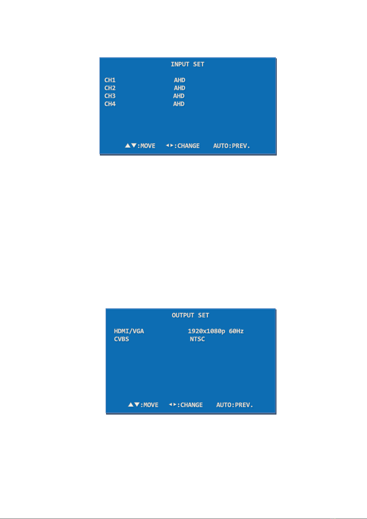
4-3. INPUT SET
Set the video input signal format.
Press the ▲▼ buttons to select the channel that you would like to set> Press the ◀▶
buttons to set the video input format among AHD, TVI, CVI, CVBS.
The camera resolution is automatically recognized. (The factory default format is AUTO. If
the video is not displayed or has some noise, please set this video input format same as
the actual input signal format)
When output of MATRIX SWITCHER is connected to input of SC-04MHD, INPUT SET
should be fixed to CVBS(NTSC) or CVBS(PAL) and LOSS OFF in SYSTEM setting.
When switching cameras in MATRIX SWITCHER, a black image may be shown on the
output screen of SC-04MHD and camera images may darkened and lightened up.
4-4. OUTPUT SET
Set the output signal resolution such as HDMI/VGA/CVBS. The output resolution of HDMI
and VGA are same.
Please check the supported resolution of monitors that are connected to SC-04MHD.
Release Version 2.0
15
When a connected monitor’s resolution is not available in SC-04MHD, the video may not
be displayed. If the video is not displayed, try to use other output port to set the
compatible resolution with monitor.
4-4-1. HDMI/VGA
Set the output resolution of HDMI and VGA.
Press the ▲▼ buttons to select HDMI> Press the ◀▶ buttons to change the output
resolution> Press the DUAL(Select) button to apply the selected resolution
(Supported Resolution: 1920x1080p 25/30/50/60, 1920x1080i 50/60, 1360x768/60,
1600x1200/60, 1024x768/60, 1280x720 50/60)
4-4-2. CVBS
Set the NTSC/PAL video format.
Press the ▲▼ buttons to select CVBS> Press the ◀▶ buttons to set the CVBS
format(NTSC or PAL).
To complete this setting, please press the DUAL(Select) button.
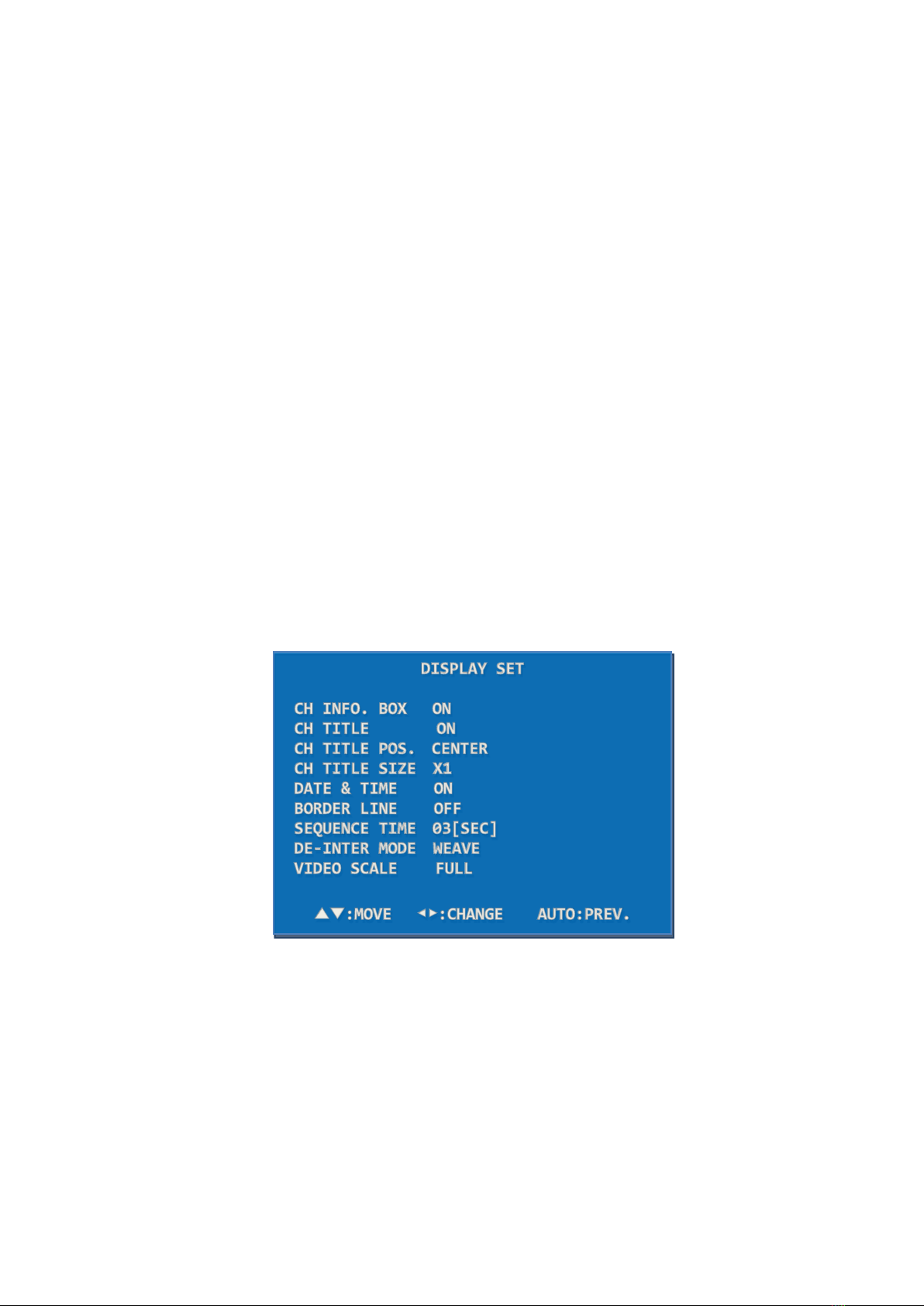
4-5. DISPLAY SET
4-5-1. CH INFO. BOX
Display the video input status on the left top of the monitor.
It disappears within 10 seconds after SC-04MHD is turned on. When the video input
signal is lost or changed, it is shown again and disappears within 10 seconds.
When it is off, the channel information will not be displayed.

Release Version 2.0
16
4-5-2. CH TITLE
Set the channel title and cropping mode message.
DISPLAY SET> Press the ▲▼ buttons to select the CH TITLE> Press the ◀▶ buttons to
set as ON/OFF. When it is off, the channel name will not be displayed on the screen.
4-5-3. CH TITLE POS.
Change the location to display the channel name(title) on the monitor screen.
DISPLAY SET> Press the ▲▼ buttons to select the CH TITLE POS.> Press the ◀▶
buttons to move the CH TITLE to the left, right, or center.
4-5-4. CH TITLE SIZE
Set the channel title size. It is possible to select X1 or X2.
DISPLAY SET> Press the ▲▼ buttons to select the CH TITLE SIZE> Press the ◀▶
buttons to set X1 / X2.
4-5-5. DATE & TIME
Set the current date and time.
DISPLAY SET> Press the ▲▼ buttons to select the DATE & TIME> Press the ◀▶ buttons
to set it ON/OFF.
4-5-6. BORDER LINE
Select whether to have the border line to distinguish the split video images easily.
DISPLAY SET> Press the ▲▼ buttons to select the BORDER> Press the ◀▶ buttons to
turn this function ON/OFF.
4-5-7. SEQUENCE TIME
Set the display switching time by seconds (3~99 seconds) in the Auto Sequence mode.
SYSTEM SET> Press the ▲▼ buttons to select the SEQUENCE TIME> Press the ◀▶
buttons to set the sequence time.
4-5-8. DE-INTER MODE
Set the scan method. In this menu, it is possible to change the video signal in the interlace
scanning method (e.g. 1920x1080 60i) to the progressive scanning method (e.g. 1920x1080
60p). When watching video of moving object recorded by a CVBS camera, the video will be
displayed unclearly with some noise. For HD analog cameras, it should be set as WEAVE
and for CVBS (NTSC / PAL) cameras, it should be set as 2D. When connecting both HD

Release Version 2.0
17
analog cameras and CVBS cameras to this splitter together, this mode should be set as 2D.
However, in this case, there might be minute image shaking.
SYSTEM SET> Press the ▲▼ buttons to select the DE-INTER MODE> Press the ◀▶
buttons to set the 2D/WEAVE.
4-5-9. VIDEO SCALE
Set the screen ratio of CVBS (NTSC/PAL) and HD Analog video to either Full, 16:9 or 4:3.
Press the ▲▼ buttons to select the VIDEO SCALE> Press ◀▶ buttons to set the video
screen ratio.
4-6. DATE/TIME SET
4-6-1. DATE FORMAT
Set the date format.
DATE & TIME SET> Press the ▲▼ buttons to select the DATE FORMAT> Press the ◀▶
to set the date format.
4-6-2. LOCATION
Set the location to display the date and time on the screen.
DATE & TIME SET> Press the ▲▼ buttons to the LOCATION> Press the ◀▶ buttons to
move the displayed date and time to the left, right or center.
4-6-3. DATE SET
Set the date.
DATE & TIME SET> Press the ▲▼ buttons to select the DATE SET> Press the ▲▼ and
◀▶ buttons to set the date.
4-6-4. TIME SET
Set the time.

Release Version 2.0
18
DATE & TIME SET> Press the ▲▼ buttons to select the TIME SET> Press the ▲▼ and
◀▶ buttons to set the time.
4-7. CH TITLE SET
Display the channel title(name) on the screen.
CH TILTE SET> Press the ▲▼ buttons to select the CHANNEL> Press the DUAL(SELECT)
button to set the channel title(name).
4-7-1. CHANNEL
Change the channel settings.
CH TILTE SET> Press the ▲▼ buttons to select the channel to be modified> Press the
DUAL(SELECT) button to enter the channel settings.
4-7-2. TITLE
Change the channel title(name). (Up to 16 letters)
Move to each letter (total: 47 letters) by using ▲▼ and ◀▶ buttons and press the
DUAL(SELECT) button to enter the selected letter. After entering the channel title, please
press the AUTO(PREV.) or ESC buttons to save the entered title and go to the CH TITLE
SET mode.
01 2 3 4 5 6 7 8 9
A B C D E F G H I J K L M
N O P Q R S T U V W X Y Z
, . / - [ ] { | } < > ESC
Release Version 2.0
19
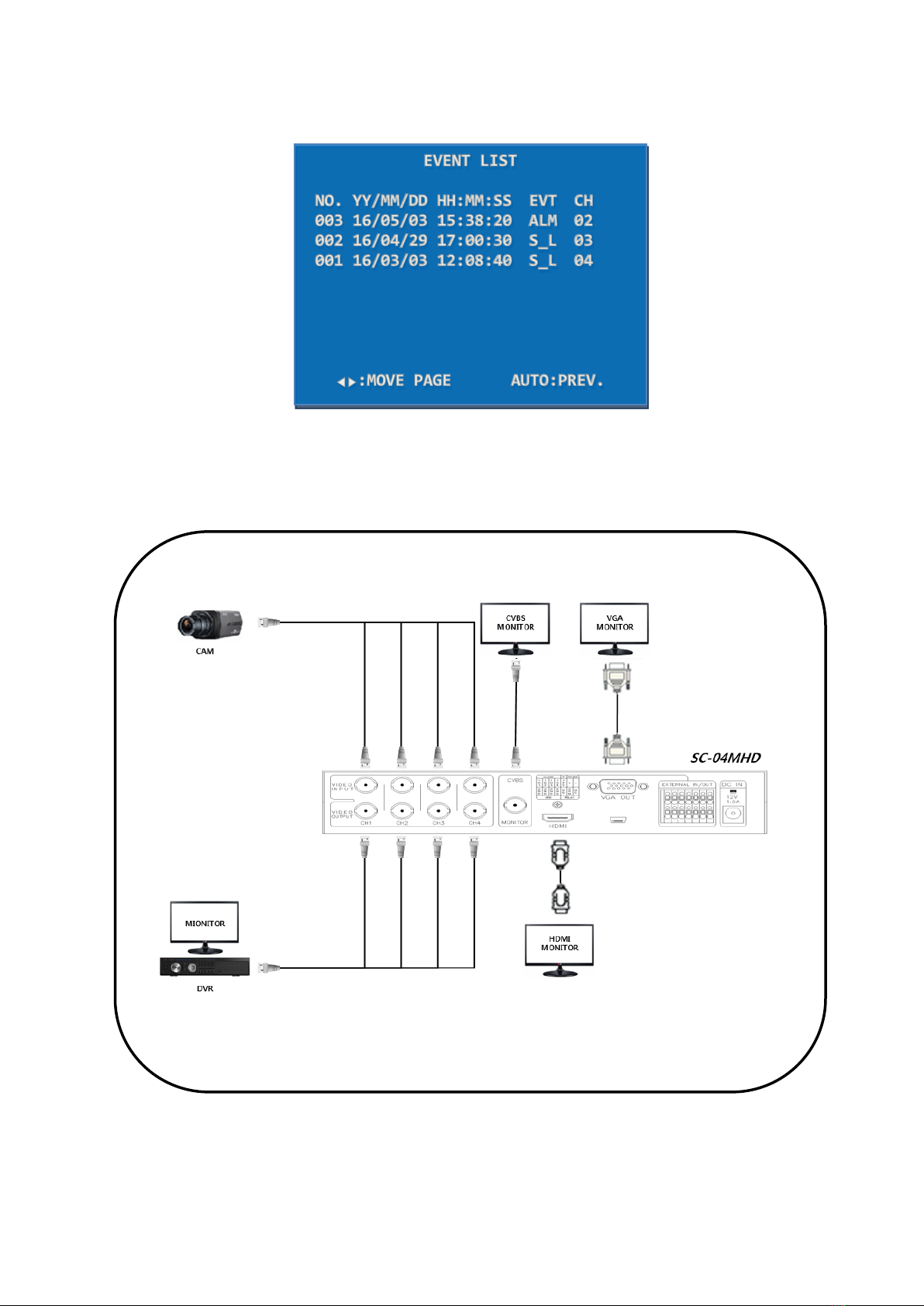
4-8. EVENT LIST
Display the relevant channel and occurred time when an alarm or video loss occurs in a
specific channel. (S_L: Signal Loss, ALM: Alarm)
5. Connection Diagram
※AHD, TVI, and CVI cameras do not have standardized signal format, so depending on the
manufacturer, images may not be output properly, and UTC control may not work properly.
※Do not connect the cable to the port when Loop Output is not used.
Table of contents
Other SeeEyes Cables And Connectors manuals
 User manual")

Popular Cables And Connectors manuals by other brands

Kidde
Kidde Alarmline II Analogue installation instructions

Rockwell Automation
Rockwell Automation Allen-Bradley Kinetix 2090 Series installation instructions

SCHÜTZE
SCHÜTZE K3-450A22 operating instructions

ELEKTRA
ELEKTRA SelfTec DW installation manual

Tektronix
Tektronix Keithley 8020-SHV manual

Scheppach
Scheppach HSC130 Translation of original instruction manual


