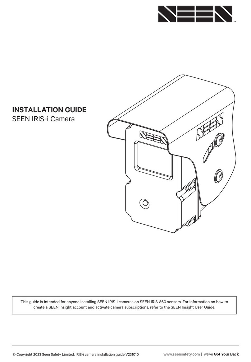
Seen IRIS-i User manual

© Copyright 2022 Seen Safety Limited. IRIS-i camera installation guide V2.3 1
INSTALLATION GUIDE
SEEN IRIS-i camera
This guide is intended for anyone installing SEEN IRIS-i cameras on SEEN IRIS-860 sensors. For information on how to
create a SEEN Insight account and activate camera subscriptions, refer to the SEEN Insight User Guide.
www.seensafety.com | we’ve Got Your Back

© Copyright 2022 Seen Safety Limited. IRIS-i camera installation guide V2.3 2
Contents
Before you start 3
Overview 3
Requirements 3
Installation 4
Antenna 5
LED indication 5
Troubleshooting 5
Internal memory 6
Maintenance 6
Warranty 7
Specifications 7
Seen Safety Limited
Unit 4, 69 Kaiwharawhara Road
Wellington 6035,
New Zealand
+64 4 381 4475
www.seensafety.com
support@seensafety.com
Important
Install and test the IRIS 860 sensor before
installing the IRIS-i camera.
Maximum 80V DC power supply.
Voltages exceeding 80V may result in
damage to the camera and will not be
covered by the warranty.
This installation and set-up guide has been
prepared with all due care and attention,
however, Seen Safety Limited cannot be
held responsible for any errors or omissions
in this guide or any consequences thereof.
In the box
• IRIS-i camera
• 300mm M12 connector cable
• Weather shield
• Mounting bracket
• Antenna
• Antenna mounting bracket
• 4 x M6 x 12mm hex head screw
• 2 x M6 x 16mm hex head screw
• 2 x M6 Nylock nut

© Copyright 2022 Seen Safety Limited. IRIS-i camera installation guide V2.3 3
Before You Start
• Fully install and test the IRIS 860 sensor before attaching
the IRIS-i camera.
• Read these instructions in full before starting.
• IRIS-i cameras do not record sound.
• Each camera must be activated in SEEN Insight before the
camera can connect and upload data.
Note. Detection events are recorded and saved in the
camera memory even if the IRIS-i is not connected to the
network. These detections will be uploaded once the device
reconnects to the network. See page 6.
Overview
The IRIS-i camera is designed to be attached to an IRIS 860
sensor. Detection information is automatically uploaded by
IRIS-i to the SEEN Insight data platform insight.seensafety.com
When powered, IRIS-i cameras automatically connect to the
mobile data network via an embedded roaming SIM.
IRIS-i cameras upload the following information:
• A still image taken at the time of the detection
• The time, date, duration, and closest distance of the
detection
• The detection trace through the detection zone
• Video can be downloaded for an additional fee.
Requirements
• 3G / 4G mobile coverage.
• An installed IRIS 860 sensor with firmware 1.54 or higher, or
if a cab box is used, an IRIS 860 sensor with firmware 1.60 or
higher. The sensor firmware version can be checked in the
IRIS 860 setup app.
• A SEEN Insight account. This can be created for free at
insight.seensafety.com
• A SEEN Insight subscription for each connected camera.
•
IRIS 860 sensor and IRIS-i camera
IRIS 860 sensor and IRIS-i camera (back)

© Copyright 2022 Seen Safety Limited. IRIS-i camera installation guide V2.3 4
Installation
Fully install and test the IRIS 860 sensor before attaching the
IRIS-i camera.
The IRIS-i camera can be attached to either side of an IRIS-860
sensor. Configure Step-1 according to which side of the sensor
the camera will be mounted on.
Step 1
2 x M6 x 12mm + nylock nut. 10Nm
Step 3
2 x M6 x 12mm. 10Nm
(M12 plug sockets at bottom)
Step 5
Connect sensor
and camera
Step 4
Transfer sensor power
cable to camera
Step 2
2 x M6 x 16mm. 10Nm
Power
Note the sensor accessory
socket is not used to
connect the camera, and
remains free for other
sensor accessories.

© Copyright 2022 Seen Safety Limited. IRIS-i camera installation guide V2.3 5
Antenna Connection
1. The antenna should be mounted upright with minimal
shading from metallic surfaces. (Before attaching the
antenna check that the antenna cable is long enough to
reach back to the camera.)
2. Connect the antenna cable to the centre antenna socket.
Finger tighten only, do not use tools.
LED Indication
BLUE LED
A solid blue LED indicates that the IRIS-i is powered and is
communicating with the IRIS 860 sensor.
GREEN LED
A solid green LED indicates that the IRIS-i is connected to the
mobile data network.
FLASHING LED
A flashing LED (either blue or green) indicates that the IRIS-i
camera cannot communicate with the IRIS 860 sensor.
Troubleshooting
IRIS-i LED is not blue
• Check the cables are correctly installed and the camera is
receiving power.
Note. A USB power supply may not supply suicient power
for the camera to function correctly, even if the blue LED is
on. The power source must be capable of supplying 24W.
IRIS-i LED does not turn green
• Even in areas with strong mobile coverage the IRIS-i may
take several minutes to first connect to the network.
• In areas with a weak mobile signal connection may take up
to 15 minutes.
• If the LED does not turn green try moving the machine to an
area with a stronger mobile signal.
• Check the antenna cable is correctly fastened.
• Try repositioning the antenna to get a clearer signal.
• Restart the IRIS-i. It must be powered o for more than 10
seconds to fully shut down.
IRIS-860 sensor LED is not green
• Check the sensor is correctly connected to the camera and
that the camera is receiving suicient power.
LED
Antenna socket
5 pin power socket
8 pin sensor socket
Antenna cable to
IRIS-i camera
Top

© Copyright 2022 Seen Safety Limited. IRIS-i camera installation guide V2.3 6
Internal Memory
The IRIS-i camera’s internal memory stores detection data
until it is uploaded to SEEN Insight, or it is over-written by new
data.
Detection event data
Information about each detection event (data and still-image)
is automatically uploaded to the SEEN Insight platform when
the camera is online. If the network connection is lost, the
camera can store up to 1,000 detection event records. These
will be uploaded when the camera next connects.
Detection event video clips
The camera can store approximately 12,0001past detection
event videos before they start to be over-written. Detection
event videos that are still in the camera’s memory can be
download from SEEN Insight on a pay-per-view basis. Once
the camera’s memory buer is full, the oldest videos will start
to be over-written by new detection event videos. Sound is
not recorded.
Rolling video buer
A 6 hour rolling video buer is saved to the camera’s memory.
This video buer is continuously over-written by new material
when the camera is powered on. Sound is not recorded.
Emergency procedure
In the event of an emergency the camera should be removed
from the machine to ensure data is not over-written or lost.
Contact support@seensafety.com
*The exact number will vary depending on the duration of each
event.
Maintenance
IRIS-i cameras have no user-serviceable parts. Establish a
regular procedure to check for window contamination. The
window should be cleaned with clean water and a soft cloth to
avoid scratching. Avoid all solvents, degreasers, petroleum or
alcohol cleaning products.
The camera is rated IP67.
Do not use high pressure water jets to clean.
1 The exact number will vary depending on the duration of
each event.

© Copyright 2022 Seen Safety Limited. IRIS-i camera installation guide V2.3 7
Specifications
Input power DC12-80V. Electrical 2.0A Standards FCC Part 15
PTCRB
EN 301489 EMC emissions and immunity
Direction signal input DC 3.5-100V electrical 1mA Ingress protection IP67. Protected from dust ingress and water
ingress at 1 metre submersion for 30 minutes.
Avoid high pressure water jets
Power consumption 24W max with attached sensor plus
sensor accessory
Enclosure ASA injection moulded plastic
Camera field of view 70 degrees horizontal x 55 degrees
vertical
Window Hard coated PMMA with oleophobic and anti-
reflective coatings.
Maintenance Clean with water and a soft clean
cloth. Avoid all solvents, degreasers,
petroleum or alcohol cleaning products
Operating
temperature -20 to +60 degrees C ambient
Connectors M12 5-pin (power supply)
M12 8-pin (to sensor)
Dual SMA antenna connectors
(Primary RF connector in centre)
Dimensions 110mm H x 64mm W x 66mm D
Weight 0.26kg
IRIS-i camera label
SEEN IRIS-i camera
DC 12-24V 24W
IP67 NA modem
Made in Thailand
www.seensafety.com
Warranty
IRIS-i cameras have been designed for reliable long-term use
on industrial vehicles in indoor or outdoor applications. The
camera is covered by a 1 year repair or replacement warranty
on materials and workmanship. The warranty excludes general
wear and tear, physical damage caused by direct impact
to the camera, over-tightening or misalignment of the M12
connectors, damage to the camera window, damage caused by
high-pressure water jets, damage caused by chemical cleaners
(including alcohol, benzene, thinners, and degreasers), or
damage caused by over-voltage to the power supply. IRIS-i
camerass have no user serviceable parts. Opening the
enclosure will void the warranty.
SCN0023
A0001234
Example camera serial number
SCN0023A0001234

© Copyright 2022 Seen Safety Limited. IRIS-i camera installation guide V2.3 8
Power socket (M12 5-pin)
Pin Name Description Direction Max.
input
voltage
Min.
input
voltage
Input
high
voltage
Input
low
voltage
Output
high
voltage
Output
low
voltage
Conditions Notes
1 Vin + Supply positive Input 92v 10.8v - - - - - 24W maximum power draw
2 Vin – Supply negative
(ground)
- - - - - - - - System / chassis ground
3 System
status
High when
system operating
Output - - - - 5.5v max.
4.5v min.
2.7K Ohm load
to ground
PNP output
4 Detection High when target
detected
Output - - - - 5.5V max
4.5V min.
2.7K Ohm load
to ground
PNP output
5 Direction
signal in
Input Input 100v 0v 3.5v min. 1v max. - - - Input current is less than
1.0 mA
Sensor socket (M12 8-pin)
Pin Name Description Direction Max.
input
voltage
Min.
input
voltage
Input
high
voltage
Input
low
voltage
Output
high
voltage
Output
low
voltage
Conditions Notes
1 Vout + Supply output to
IRIS 860 sensor
Output - - - - 16v - Limits IRIS 860 supply
voltage to 16V
2 Vout - Supply negative
(ground)
- - - - - - - - System / chassis ground
3 Reserved
4 Reserved
5 Direction Direction signal
output to sensor
Output - - - - 16V max
6.8V min.
- 10K ohm load
to ground
PNP output
6 Trigger in Camera trigger
input
Input 30V 0V 3.5V
min.
0.7V
max
High impedance external
trigger input for the camera
Product specifications are subject to change without notice to improve reliability, function, design or otherwise.
5 pin power socket
8 pin sensor socket

www.seensafety.com | we’ve Got Your Back
SEEN IRIS-i Installation Guide V0.2 [PROTOTYPE]
Seen Safety Limited
Unit 6, 69 Kaiwharawhara Road
Wellington 6035, New Zealand
+64 4 381 4475
www.seensafety.com
support@seensafety.com
IMPORTANT. SEEN IRIS 860 sensors can provide collision warning assistance to the operator but do not replace the need for
proper operator training and best practice safe operating procedure. While IRIS 860 sensors can alert the machine operator
to a potential collision, the operator is always fully responsible for the safe operation of the equipment. IRIS 860 sensors do
not comply with the regulatory standards required for devices which are intended to directly control vehicle or machine safety
functions. Using the sensor accessory port to control a vehicle or machine function is entirely at your own risk. Detection can
never be guaranteed.
Copyright © 2021 Seen Safety Limited. All rights reserved. International patents pending and granted. Seen, Seen Safety, IRIS,
IRIS-i are trademarks of Seen Safety Limited.
Other manuals for IRIS-i
1
Table of contents
Other Seen Digital Camera manuals
Popular Digital Camera manuals by other brands
Omron
Omron STC-MBS2041POE Product specifications and user's guide

Canon
Canon PowerShot SX710 HS Connection guide

Panasonic
Panasonic Lumix DMC-FX78 Basic owner's manual
Panasonic
Panasonic DMC-FX37A - Lumix Digital Camera Instrucciones básicas de funcionamiento
Canon
Canon Digital REBEL 300D Function guide
CRX
CRX ST0570 instruction manual
Canon
Canon EOS R50 instruction manual

Samsung
Samsung Vluu PL170 Manual Del Usuario
Polaroid
Polaroid PhotoMAX PDC 1100 Quick start card
Omron
Omron STC-SBS312POE Product specifications and user's guide

Kodak
Kodak PALM m500 user guide
Sony
Sony DSLR-A580L - alpha; Interchangeable Lens Digital Camera... Specifications
