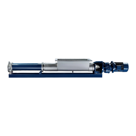
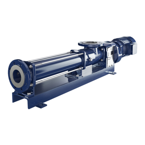
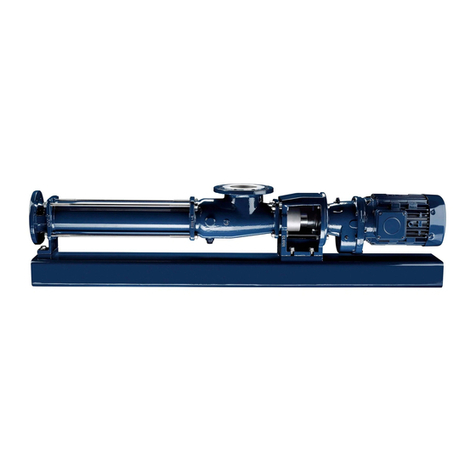
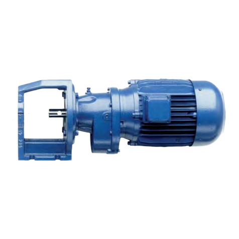
Seepex BCSB Series Product guide

Issue .0.2017
Not Binding Operating
and Assembly Instruction
Progressive Cavity Pump
This operating and assembly instruction is only
for general information.
Type
B&6%1-6WR/7


Index
Index
Index
Index
1
1
1
1 Safety
Safety
Safety
Safety....................................................................................................................................................
....................................................................................................................................................
....................................................................................................................................................
....................................................................................................................................................1
1
1
1
1.1 General notes
1.2 Safety and warning notes
1.2.1 Warning notes
1.2.2 Danger symbols
1.2.3 Information symbols
1.3 Dangers that can be caused by the machine
1.4 Qualification of the personnel
1.5 Authorised people
1.5.1 Tasks and information for the owner/operators
1.5.2 Safety notes for maintenance, inspection and assembly work
1.6 Personal protective equipment
1.7 Safety and protective devices
1.8 Foreseeable misuse
1.9 Designated use
1.10 Warranty
2
2
2
2 Description of the pump
Description of the pump
Description of the pump........................................................................................................................
........................................................................................................................
........................................................................................................................
........................................................................................................................5
5
5
5
2.1 General description
2.2 Mode of action and pumping principle of the pump
2.3 Constructive design
3
3
3
3 Technical Data
Technical Data
Technical Data
Technical Data......................................................................................................................................
......................................................................................................................................
......................................................................................................................................
......................................................................................................................................6
6
6
6
4
4
4
4 Transport, Intermediate storage, Disposal
Transport, Intermediate storage, Disposal
Transport, Intermediate storage, Disposal............................................................................................
............................................................................................
............................................................................................
............................................................................................8
8
8
8
4.1 Safety
4.2 Transport
4.2.1 Dimensions, weight and centre of gravity
4.2.2 Symbol
4.2.3 Lashing points (AP) for lifting devices
4.2.4 Unpacking the machine
4.3 Temporary storage/corrosion protection
4.4 Disposal

Index
Index
Index
Index
5
5
5
5 Assembly / Installation
Assembly / Installation
Assembly / Installation........................................................................................................................
........................................................................................................................
........................................................................................................................
........................................................................................................................ 11
11
11
11
5.1 Mounting tools / lifting gear
5.2 Space requirement
5.2.1 Dimension for stator replacement
5.3 Assembly of the complete mounted pump
5.4 Power supply of the pump
5.5 Pipelines
5.5.1 Suction and pressure connection
5.5.2 Pipeline dimensions
5.5.3 Residue-free pipelines
5.5.4 Tension-free assembly
6
6
6
6 Commissioning / De-Commissioning
Commissioning / De-Commissioning
Commissioning / De-Commissioning..................................................................................................
..................................................................................................
..................................................................................................
..................................................................................................13
13
13
13
6.1 Commissioning report............................................................................................................ 13
6.2 Measures before commissioning............................................................................................14
6.2.1 Checking pipelines
6.2.2 Protective devices on the pump
6.2.3 Electrical / hydraulic connections
6.2.4 Direction of rotation check
6.2.5 Additional devices - optional
6.3 Initial commissioning/repeated commissioning
6.3.1 Avoiding dry running of the pump
6.3.2 Pressure in the suction and pressure connection
6.4 De-commissioning
6.4.1 Switching off the pump
6.4.2 Emptying the pump
6.4.3 Dismantling the pump
6.4.4 Preservation/storage of the pump
7
7
7
7 Maintenance
Maintenance
Maintenance
Maintenance.......................................................................................................................................
.......................................................................................................................................
.......................................................................................................................................
....................................................................................................................................... 19
19
19
19
7.1 Preventative measures
7.1.1 Pump down-time
7.2 Lubrication
7.2.1 Joint grease
7.3 Inspection
7.4 Cleaning of CS pumps........................................................................................................... 21
8
8
8
8 Malfunctions, causes, rectification
Malfunctions, causes, rectification
Malfunctions, causes, rectification......................................................................................................
......................................................................................................
......................................................................................................
...................................................................................................... 26
26
26
26
9
9
9
9 Pump Dismantling / Reassembly
Pump Dismantling / Reassembly
Pump Dismantling / Reassembly........................................................................................................
........................................................................................................
........................................................................................................
........................................................................................................29
29
29
29
9.1 Pump Dismantling / Reassembly........................................................................................... 29
9.1.1 Prepare the pump for dismantling
9.1.2 Dismantling
9.1.3 Reassembly

Index
Index
Index
Index
9.2 Rotating unit – individual parts .............................................................................................. 29
9.2.1 Dismantling
9.2.2 Rotating unit (RTE) - prepare individual parts for reassembly
9.2.3 Rotating unit (RTE) - individual parts - reassembly
9.3 Holding band - assembly........................................................................................................33
9.3.1 Prepare the holding band
9.3.2 Check the holding band
9.3.3 Assembling the holding band
9.3.4 Correct tension for the holding band (HBD)
9.3.5 Cant up the holding band
9.3.6 Shear the holding band
9.3.7 Check the holding band after assembly
9.4 Mechanical seal ..................................................................................................................... 35
9.4.1 Safety
9.4.2 Application conditions and material version
10
10
10
10 Spare parts
Spare parts
Spare parts
Spare parts.........................................................................................................................................
.........................................................................................................................................
.........................................................................................................................................
......................................................................................................................................... 36
36
36
36
10.1 Order template for spare parts............................................................................................... 38
11
11
11
11 Special tools
Special tools
Special tools
Special tools.......................................................................................................................................
.......................................................................................................................................
.......................................................................................................................................
....................................................................................................................................... 41
41
41
41
12
12
12
12 Related documents
Related documents
Related documents
Related documents.............................................................................................................................
.............................................................................................................................
.............................................................................................................................
.............................................................................................................................42
42
42
42
13
13
13
13 Appendix
Appendix
Appendix
Appendix.............................................................................................................................................
.............................................................................................................................................
.............................................................................................................................................
.............................................................................................................................................44
44
44
44
13.1 Manufacturer's documents / suppliers
Subsidiaries
Subsidiaries
Subsidiaries
Subsidiaries


1
Ausgabe
issue D / 06.01.2014 Dokument
document OM.SAF.01e Blatt
sheet 1 (4)
1
Safety
1.1 General notes
¾Always keep the operating and maintenance instructions close by the machine.
¾If problems cannot be solved with reference to the operating and maintenance instructions,
please contact the manufacturer.
Observe the following points in addition to these operating and maintenance instructions:
• Prohibition, warning and mandatory signs, warning notes on the machine
• Relevant laws and ordinances
• Statutory provisions on accident prevention
• Corresponding harmonised standards and regulations
1.2 Safety and warning notes
¾Comply with safety and warning notes for safe and efficient use of the product.
Signal words for specific dangers and (possible) consequences are explained below. These
are supplemented by symbols (pictograms) if necessary.
1.2.1 Warning notes
1.2.2 Danger symbols
NOTICE
Caution for machine!
Possible danger.
Material damage can occur.
CAUTION
Caution for people and machine!
Possible danger.
Minor injury or damage to property can occur.
WARNING
Warning for people!
Possible danger.
Death or serious injury can occur.
DANGER
Danger for people!
Possible danger.
Immediate risk of sever or fatal injury.
Warning:
Suspended load. Warning:
Dangerous electrical
voltage.

2
Ausgabe
issue D / 06.01.2014 Dokument
document OM.SAF.01e Blatt
sheet 2 (4)
1
Safety
1.2.3 Information symbols
¾Instruction to act/take measures
• List item
1.3 Dangers that can be caused by the machine
seepex machines are built in accordance with the state of the art.
Nevertheless, there is a residual risk, because the machine works with:
• Mechanical movements that pose a danger
• Electrical voltages and currents
We have used design measures and applied safety technology to minimise the risk to the
health of people posed by this danger.
1.4 Qualification of the personnel
This handbook is intended for:
• Owner
• Operators
•Setters
• Maintenance personnel
1.5 Authorised people
People authorised to undertake operation, set up and maintenance are instructed and trained
specialists employed by the owner/manufacturer.
The owner is responsible for:
• Personnel training
• Compliance with safety regulations
• Compliance with operating and maintenance instructions
The operator must:
• Have received instruction
• Read and understood the relevant parts of the operating instructions before starting work
• Know the safety devices and regulations
NOTICE
Ensure environmen-
tal protection. Wear eye protection.
Detailed technical knowledge is essential for performing any work on the machine.

3
Ausgabe
issue D / 06.01.2014 Dokument
document OM.SAF.01e Blatt
sheet 3 (4)
1
Safety
1.5.1 Tasks and information for the owner/operators
¾Regularly check and maintain the machine, replacing all parts in good time which no longer
guarantee safe operation.
¾It is essential to comply with the procedure described in the operating instructions for shut-
ting down the machine.
• On completion of work, attach all safety and protective devices and make sure they are
functioning.
1.5.2 Safety notes for maintenance, inspection and assembly work
¾Do not work on the machine or system unless it is stationary and depressurised.
¾Switch off the master switch and pull out the power plug before starting work on live com-
ponents.
¾Comply with the procedure for shutting down the machine as described in the Shut-down
chapter.
¾Decontaminate (de-toxify) machines that are used for pumping media that can be harmful
to health.
¾Refer to the Initial start-up chapter before repeated start-up of the machine.
1.6 Personal protective equipment
¾Wear personal protective equipment and/or additional equipment for your own safety.
¾Avoid/limit risks by the use of collective technical protective equipment or by organisational
measures at work.
1.7 Safety and protective devices
¾Prior to start-up, bolt seepex machines onto a concrete foundation so as to ensure stability.
¾Starting and stopping devices must be clearly recognisable. Take appropriate measures to
avoid defects.
• No protective device is necessary for checking and/or setting the shaft seal.
• Hot surfaces are identified with a danger symbol on the machine.
1.8 Foreseeable misuse
Serious personal injury and damage to property can be caused by:
• Incorrect use
• Incorrect installation or operation of the machine
• Impermissible removal of necessary protective equipment

4
Ausgabe
issue D / 06.01.2014 Dokument
document OM.SAF.01e Blatt
sheet 4 (4)
1
Safety
1.9 Designated use
• Only use seepex machines if they are in perfect condition and in compliance with the oper-
ating and maintenance instructions.
• Do not start up the machine unless the system in which the machine is installed is in accor-
dance with the provisions of the applicable guidelines and statutory regulations.
• Equivalent sustained sound pressure level at workplaces of operating personnel C75 dB
(A). Cavitation-free operation of the machine and screwed connection to concrete founda-
tion are essential.
• seepex machines are components that are exclusively intended for pumping media in ac-
cordance with the technical data (→chapter 3). Written approval must be obtained from the
manufacturer before other media are pumped.
• Refer to the information on the type plate and the operating instructions for technical data
(→chapter 3), and comply with them.
• The operating instructions are assigned to the seepex machine based on the commission
number.
Fig. 1-1 Similar illustration
1.10 Warranty
• Warranty in accordance with our terms and conditions of delivery and order confirmation.
• It is a condition of the machine warranty that the machine must correspond to the listed op-
erating instructions in accordance with the type plate/data sheet.
• All wearing parts are excluded from the warranty.
• Theseoperatinginstructionsaresubject to copyright.Reproductionisnot permitted and will
be punished. Contravention will be pursued through the courts.

5
Ausgabe
issue B / 12.11.2012 Dokument
document OM.DES.01e Blatt
sheet 1 (1)
2
Description of the pump
2.1 General description
seepex pumps are members of the group of rotating displacement pumps.
• Characteristic features
– Special configuration/arrangement of the rotor and stator pumping elements.
– Motion sequence
2.2 Mode of action and pumping principle of the seepex pump
• Sealing bands are produced through geometric design/contact of both conveying elements.
• Sealing bands ensure a perfect fit between the suction and pressure side.
Result:
– Increased pump suction.
– Higher pressure build-up independent of speed possible.
2.3 Constructive design
No. Designation
ANT Drive
200 Lantern
307 Plug-in shaft
400 Coupling rod
SEA Shaft seal
500 Suction casing
600 Rotor
RTE Rotating unit
601 Stator
700 Pressure branch

6

7
Ausgabe
issue A / 29.06.2017 Dokument
document OM.TED.XXeBlatt
sheet 1 (1)
3
Technical data
3.1 Data sheet
3.2 Characteristic Curves
3.3 Declaration
•Data sheet, characteristic curves and declarations are commission specific documents
and not part of this not binding operating and assembly instruction.

8

9
Ausgabe
issue D / 27.08.2012 Dokument
document OM.TRA.01e Blatt
sheet 1 (2)
4
Transport, Intermediate storage, Disposal
4.1 Safety
4.2 Transport
4.2.1 Dimensions, weights and center of gravity
¾Note the dimensional drawing (→ chapter 5.6).
4.2.2 Symbols • Meaning of symbol
4.2.3 Sling points (AP) for lifting devices
4.2.4 Unpacking the machine
¾Comply with the symbols and notices on the packaging.
¾Remove the screwed connection between the machine and packaging.
¾Remove the machine with a lifting machine/industrial truck.
4.3 Temporary storage/Corrosion protection
• All seepex machines have corrosion protection applied as standard prior to transport.
CAUTION
Damage to property/injuries due to incorrect transport
Slight injury or damage to property can occur
¾Comply with the safety notes and transport notes on the packaging.
¾Use suitable means of transport, lifting devices and tools.
¾Use protective equipment.
Top Fragile
item Againstmoisture
protect Centre of gravity Lashing points
WARNING
Warning of suspended load.
Death of serious injury can occur.
¾Use the lashing points (AP) for lifting divices.
¾Note the centre of gravity (→ dimensional drawing, chapter 5.6).
Lifting machine Industrial trucks

10
Ausgabe
issue D / 27.08.2012 Dokument
document OM.TRA.01e Blatt
sheet 2 (2)
4
Transport, Intermediate storage, Disposal
4.4 Disposal
NOTICE
Damage to property if corrosion protection is missing
Property damage can occur due to corrosion.
¾Temporary storage must be in a dry, enclosed, frost-free room in order to provide protec-
tion against ambient influences.
¾Contact seepex regarding the necessary corrosion protection for temporary storage.
NOTICE
Environmental protection
Material damage can occur.
¾Drain the pumping medium and dispose of it in accordance with the regulations.
¾Dispose of the machine with regard to its composition and existing regulations.

11
Ausgabe
issue C / 11.10.2012 Dokument
document OM.INS.01e Blatt
sheet 1 (2)
5
Assembly / Installation
5.1 Mounting tools / lifting gear
5.2 Space requirement
The required space should be determined by considering the following factors:
• Dimensions and weight.
• Requisite transport and lifting equipment.
• Pipe routing – dismantling (dimension for stator replacement).
5.2.1 Dimension for stator replacement (P)
5.3 Assembly of the complete mounted pump
¾Assemble according to technical data (→ chapter 3.).
¾Note dimensional drawing.
Tension-free mounting of the pump
¾Balance unevenness with suitable supports.
• Applies to mounting on foundations/load-bearing elements.
• Total areas of all pump bearing areas are resting on the surface.
Correct position of the drives
• All drives are set up ready for operation and mounted.
• Correct displacements of the drive during transport/installation of the pump by adjusting/fix-
ing the drive.
CAUTION
Pump falling over.
Slight injury or damage to property can occur.
¾Adhere to the lifting tool’s starting point.
¾Pay attention to the dimensions, weight and centre of gravity of the pump.
¾Use suitable mounting tools/lifting gear.
¾Refer to the dimensional drawing.
CAUTION
Safety protection equipment.
Slight injury or damage to property may result.
¾Connect safety protection equipment and activate.

12
5
Assembly / Installation
Ausgabe
issue C / 11.10.2012 Dokument
document OM.INS.01e Blatt
sheet 2 (2)
5.4 Power supply of the seepex pump
5.5 Pipelines
5.5.1 Suction and pressure connection
• Refer to the dimensional drawing for the position, nominal width and standard.
• Note direction of rotation/flow direction.
5.5.2 Pipeline dimensions
• Adhere to specifications regarding pressure in the pressure respectively suction connec-
tion.
• Note technical data (→ chapter 3.).
• Nominal width of suction pipe = nominal width of suction connection of pumps.
5.5.3 Residue-free pipelines
5.5.4 Tension-free assembly
¾Assemble pipelines and other components in a tension-free manner on the pump.
DANGER
Supply voltage and power frequency.
Death or serious injury will result.
¾Heed type plate on the pump.
¾Pay attention to manufacturer’s directions (→ chapter 13.).
¾Pay attention to safety regulations.
NOTICE
Damage to property through assembly residue.
No claims under guarantee if violated.
¾Keep all pipe work free of foreign objects.
¾Remove weld spatters, screws, steel chips etc.

13
Ausgabe
issue B / 17.03.2006 Dokument
document OM.COM.05e Blatt
sheet 1 (1)
6
Commissioning / De-commissioning
Master Copy
6.1 Commissioning report
Send commissioning report online to
www.seepex.com\ From:
Must be specified with every order!
Commission: Model: Contact person: .............................................
_________________________ _____________________ Tel.: ................................................................
Fax: ...............................................................
E-mail: ...........................................................
Customer Service:
seepex GmbH
Postfach 10 15 64
D-46215 Bottrop
Germany Phone:+49 2041.996-231
Fax: +49 2041.996-431 Address of plant:
.......................................................................
Rest of
Europe Phone:+49 2041.996-224
Fax: +49 2041.996-424 .......................................................................
.......................................................................
Europe Phone:+49 2041.996-120
Fax: +49 2041.996-432 .......................................................................
.......................................................................
Delivery date:
Date of installation:
Assembly check carried out on:
Please enter operational data:
Conveying liquid:
Temperature:
Fuse level/motor protection or power
consumption
Frequency control no
yes If yes:
Supplied by seepex
Supplied by customer
Frequency:
Speed:
Power
consumption:
________________________________ _______________________________________
Place, date Signature / company stamp

14
This manual suits for next models
4
Table of contents
Other Seepex Water Pump manuals

Seepex
Seepex BN 52-6LS Product guide

Seepex
Seepex BCSO 025-24 to 130-6L Product guide

Seepex
Seepex BN 2-12S Product guide

Seepex
Seepex BN 2-12S Product guide

Seepex
Seepex BW 10 Manual

Seepex
Seepex BN 5-12 Series Manual

Seepex
Seepex BTQ Series Product guide

Seepex
Seepex Macerator 110 Series Product guide

Seepex
Seepex BTVE 10-12 Product guide
Popular Water Pump manuals by other brands

Edwards
Edwards STP-L301 Series instruction manual

Pfeiffer Vacuum
Pfeiffer Vacuum MVP 015-2 Translation of the original

Flint & Walling
Flint & Walling SP10P1 manual

Nordson
Nordson 100 PLUS FB instruction sheet

Sensidyne
Sensidyne Gilian 5000 Operation manual

Crane
Crane DEMING 4201 Series Installation, operation & maintenance manual