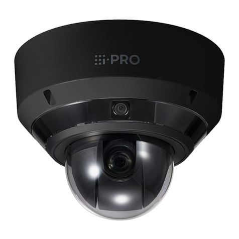
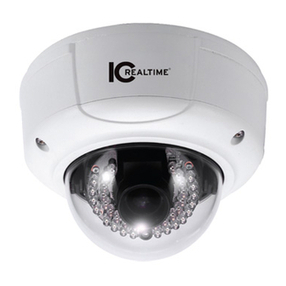
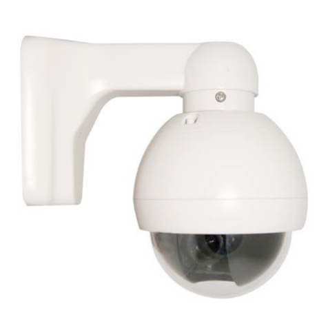
SEESTATION SS-C4457AV2 Series User manual

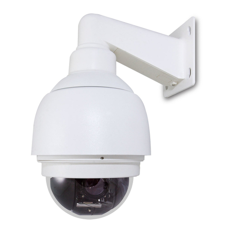
SS-C4457AV2 Series PTZ High Speed Dome
User Manual
1

Safety Attention Notes
Please read the instructions thoroughly before installing or operating the unit.
Please do not put the machine on an unstable table or mounting bracket.
Please prevent all liquids or other contaminating material from entering into the dome
housing.
When connecting to the power source, please follow all electric safety standards and only
use the power supply designated for this device. The speed dome’s RS-485 and video
signal uses TVS technology to protect it from strong electric surges. This technology
prevents damage to the device resulting from impulse signals such as lightning strikes or
surges under 500W power. Allow for enough distance between the RS-485 and video
signals and high-voltage equipment or cables during the transmission process. Please do
not power the unit until all connections are secure and installation is complete.
Avoid shooting very bright objects directly into the camera’s CCD (such as the sun or light
fittings).
◎ When the machine is not operating properly, do not casually repair it. Refer to the
instructions for trouble, if you couldn’t find the trouble; please turn to the professional
engineer for help. Our company’s engineers will provide you with the repairing service.
2

INDEX
I. Production Introduction ----------------------------------4
II.Technical Data -----------------------------------------4
2.1. Speed Dome Technical Parameter -----------------------4
2.2. Speed Dome Camera Technical Parameter -----------------5
2.3. Lens Technical Parameter ----------------------------------5
III. Dome Camera Installation and Setting ------------------6
3.1. Dome Camera Setting --------------------------------------6
3.2. SW1 Switch Setting ---------------------------------------6
3.3. SW2 Switch Setting -----------------------------------------6
IV. Wall Mount Installation Connection -----------------------13
4.1. Dome Camera Wall Mount Installation ---------------------13
4.1.1 Wall Mount Bracket and Cover Installation -------------------13
4.1.2 Wire Connection -------------------------------------------13
4.1.3 Core Mounting --------------------------------------------13
4.1.4 Electricity --------------------------------------------------15
4.1.5 Dome Mount ------------------------------------------------14
4.2. Dome Camera Ceiling Installation -------------------------14
4.2.1 Holing on The Ceiling ----------------------------------14
4.2.2 Housing Installation --------------------------------------14
4.2.3 Wire Connection -------------------------------------------14
4.2.4 Core Mounting ---------------------------------------------15
4.2.5 Electricity --------------------------------------------------15
4.2.6 Dome Mounting --------------------------------------------15
V. Functions and Operations --------------------------16
5.1. Object Tracking ----------------------------------------16
5.2. Setting and Calling Preset Position -----------------------16
5.3. Dome Pattern Tours ------------------------------------16
5.4. Auto Scan ---------------------------------------------16
5.4.1 2 Points Scan --------------------------------------------17
5.4.2 360°Scan -------------------------------------------------17
5.5. Guard Location ------------------------------------------17
3

5.5.1 Setting the Guard Location --------------------------------17
5.5.2 Switches of Guard Location --------------------------------17
5.6. Camera Control ----------------------------------------18
5.6.1 Zoom Control --------------------------------------------18
5.6.2 Focus Control ---------------------------------------------18
5.6.3 Iris Control --------------------------------------------------18
5.6.4 Auto Backlight Compensation --------------------------------18
5.6.5 Auto White Balance ----------------------------------------18
5.7. Camera Menu Setting ------------------------------------18
VI. Trouble Shooting Chart -----------------------------20
VII. PELCO-D,PELCO-P Protocol Order -------------------21
IProduction Introduction
Congratulations on purchasing our speed dome, an intelligent, high-speed dome camera with
a high-performance DSP camera and sophisticated zoom lens. It is an advanced technological
surveillance product combining an all-direction variable speed dome and digital decoder all in
one unit. It can aim quickly and scan continuously, making omni-directional and non-blind-spot
monitoring into reality. Additionally, it can quickly adapt to changing environments with its 18x,
26x, 36x optical and 12x digital zoom with precise stepping motors. The advanced stepping
motor technologies enable the dome to rotate memorizing function when the power cuts off,
can auto resume to previous working status before the power cuts off. Use the
high-performance speed dome “When it counts.”
All of the features make the intelligent high-speed dome camera fit for a wide range of
applications such as intelligent building, bank, street of city, airport, station etc.
II Technical Data
2.1. Speed Dome Technical Parameter
Power Supply AC24V ±5%
Operating Temperature Indoor:(0ºC-+40ºC)
Outdoor:(-40-+60)
Operating Humidity ≤95% Non Considering
Power Consumption 20W
Communication RS485
Baud Rate 1200/ 2400/4800/9600 bps
Horizontal Rotation Speed 0.5º-280º
Horizontal Rotation Range 360º unlimited
Tilt Rotation Range 90º
Auto Flip Rotates 180° when camera tilts to the
vertical position
4

Auto Zoom Speed Control Control speed auto-adjusted according to
zoom length changing
2 Points Scan Set Freely
2 Points Scan Speed 1-64 grade available
Dwell Time(2 Points scan) 1-60s Available
Preset Positions 128
Running to Preset Speed: 0.5º-280°
Cruise Tour: 4Group(Pelco with temporary 1 group)
Cruise Points Per Cruise Group 16 Preset Positions
Fan and Heater Auto start 24VAC
2.2.
Speed Dome Camera Technical Parameter
Synchronism Internal/ External
Scan 2:1 Interlace
Resolution >480 TV Lines
Minimum Illumination 0.7Lux/0.01 Lux
Backlight Compensation Yes
White Balance Auto
Gain Auto
Signal NTSC/PAL
S/N Ratio >55dB
Video Signal Output 1.0±0.2Vp-p
2.3. Lens Technical Parameter
Optical Zoom 18X 26X 36X
Digital Zoom 12x ( 216x in total ) 12x ( 312x in total ) 12x ( 432x in total )
Lens
f=4.1 mm (Wide) to
73.8 mm (Tele), F1.4
to F3.0
f=3.5 mm (Wide) to
91.0 mm (Tele), F1.6
to F3.8
f=3.4 mm (wide) to
122.4 mm (tele), F1.6
to F4.5
Viewing angle (H) 48.0° (Wide end) to
2.8° (Tele end)
54.2° (Wide end) to
2.2° (Tele end)
57.8° (wide end) to
1.7° (tele end)
Focus Auto/Manual
Iris Control Auto/Manual
5

III Dome Camera Installation and Setting
3.1. Dome Camera Controlling
Notice: To assure the normal signal communication, a 120 ohm R should be connected to the
farthest dome when one control bus control more than two domes.
3.2. SW1 Switch Setting
Note: SW1 switch is used for setting communication protocol.
ON=1,OFF=0
Protocol SwitchSetting
SW1-1 SW1-2 SW1-3 SW1-4 SW1-5 SW1-6 SW1-7 SW1-8
Matrix
Protocol(9600
)
0 0 0 0 0 0 0 0
PELCO-P
Protocol 1 0 0 0 0 0 0 0
PELCO-D
Protocol(2400
)
0 1 0 0 0 0 0 0
3.3. SW2 Switch Setting (PELCO-P/PELCO-D)
Note: SW2 switch is used for setting the receiving address and baud rate.
It is effective only in PELCO-P/PELCO-D protocol
ON=1,OFF=0
6

Baud Rate SW2-6 SW2-7 SW2-8
1200 1 1
2400 0 1
4800 1 0
9600 0 0
Matrix Code Address Setting:
Note:Matrix code baud rate: 9600B
7

SW2- 1 SW2- 2 SW2- 3 SW2- 4 SW2- 5 SW2- 6 SW2- 7 SW2- 8 SW2- 1 SW2- 2 SW2- 3 SW2- 4 SW2-5 SW2- 6 SW2- 7 SW2- 8
1
2
3
4
5
6
7
8
9
10
11
12
13
14
15
16
17
18
19
20
21
22
23
24
25
26
27
0
1
0
1
0
1
0
1
0
1
0
1
0
1
0
1
0
1
0
1
0
1
0
1
0
1
0
0
0
1
1
0
0
1
1
0
0
1
1
0
0
1
1
0
0
1
1
0
0
1
1
0
0
1
0
0
0
0
1
1
1
1
0
0
0
0
1
1
1
1
0
0
0
0
1
1
1
1
0
0
0
0
0
0
0
0
0
0
0
1
1
1
1
1
1
1
1
0
0
0
0
0
0
0
0
1
1
1
0
0
0
0
0
0
0
0
0
0
0
0
0
0
0
0
1
1
1
1
1
1
1
1
1
1
1
0
0
0
0
0
0
0
0
0
0
0
0
0
0
0
0
0
0
0
0
0
0
0
0
0
0
0
0
0
0
0
0
0
0
0
0
0
0
0
0
0
0
0
0
0
0
0
0
0
0
0
0
0
0
0
0
0
0
0
0
0
0
0
0
0
0
0
0
0
0
0
0
0
0
0
0
0
0
0
0
0
28
29
30
31
32
33
34
35
36
37
38
39
40
41
42
43
44
1
0
1
0
1
0
1
0
1
0
1
0
1
0
1
0
1
1
0
0
1
1
0
0
1
1
0
0
1
1
0
0
1
1
0
1
1
1
1
0
0
0
0
1
1
1
1
0
0
0
0
1
1
1
1
1
0
0
0
0
0
0
0
0
1
1
1
1
0
0
0
0
0
1
1
1
1
1
1
1
1
1
1
1
1
0
0
0
0
0
0
0
0
0
0
0
0
0
0
0
0
0
0
0
0
0
0
0
0
0
0
0
0
0
0
0
0
0
0
1
1
1
1
1
0
0
0
0
0
0
0
0
0
0
0
0
10 1
00 1 1 1 00
0
11 00
0
01 11 100
0
11 11 10
0
0
00 00 100
1
1000 100
1
01 00 100
1
11 00 100
1
0010 100
1
10 10 100
1
45
46
47
48
49
50
51
52
53
54
55
56
57
58
59
60
61
62
63
64
65
66
67
68
69
70
71
72
73
74
75
76
77
78
79
80
81
82
83
84
85
86
87
88
0
1
0
1
0
1
0
1
0
1
0
1
0
1
0
1
0
1
0
1
0
1
0
1
0
1
0
1
0
1
0
1
0
1
1
1
0
0
1
1
0
0
1
1
0
0
1
1
0
0
1
1
0
0
1
1
0
0
1
1
0
0
1
1
0
0
1
1
1
1
0
0
0
0
1
1
1
1
0
0
0
0
1
1
1
1
0
0
0
0
1
1
1
1
0
0
0
0
1
1
1
1
0
0
1
1
1
1
1
1
1
1
0
0
0
0
0
0
0
0
1
1
1
1
1
1
1
1
0
0
0
0
0
0
0
0
1
1
1
1
1
1
1
1
1
1
0
0
0
0
0
0
0
0
0
0
0
0
0
0
0
0
1
1
1
1
1
1
1
1
1
1
1
1
1
1
1
1
1
1
0
0
0
0
0
0
0
0
0
0
0
0
0
0
0
0
0
0
0
0
0
0
0
0
0
0
0
0
0
0
0
0
0
0
1
1
1
1
1
1
1
1
1
1
1
1
1
1
1
1
1
1
1
1
1
1
1
1
0
0
0
0
0
0
0
0
0
0
0
0
0
0
0
0
0
0
0
0
0
0
0
0
0
0
0
0
0
0
0
0
0
0
Rec ei v i ng
Addr es s
Swi t ch Set t i ng Receiving
Addr es s
Swi t ch Set t i ng
8

89
90
91
92
93
94
95
96
97
98
99
0
1
0
1
0
1
0
1
0
1
0
1
0
1
0
0
1
1
0
0
1
1
0
0
1
1
0
0
0
0
0
0
1
1
1
1
0
0
0
0
1
1
1
1
1
1
1
1
1
1
0
0
0
0
0
0
1
1
1
1
1
1
1
1
0
0
0
0
0
0
0
0
0
0
0
0
0
0
1
1
1
1
1
1
1
1
1
1
1
1
1
1
1
1
1
1
1
1
0
0
0
0
0
0
0
0
0
0
0
0
0
0
100
101
102
SW2- 1 SW2- 2 SW2- 3 SW2- 4 SW2- 5 SW2- 6 SW2- 7 SW2- 8 SW2- 1 SW2- 2 SW2- 3 SW2- 4 SW2- 5 SW2- 6 SW2- 7 SW2- 8
0
1
0
1
0
1
0
1
0
1
0
1
0
1
0
1
0
1
0
1
0
1
0
1
0
1
0
1
0
1
0
1
0
1
0
1
0
0
1
1
0
0
1
1
0
0
1
1
0
0
1
1
0
0
1
1
0
0
1
1
0
0
1
1
0
0
1
1
0
0
1
1
0
0
0
0
1
1
1
1
0
0
0
0
1
1
1
1
0
0
0
0
1
1
1
1
0
0
0
0
1
1
1
1
0
0
0
0
1
1
1
1
1
1
1
1
0
0
0
0
0
0
0
0
1
1
1
1
1
1
1
1
0
0
0
0
0
0
0
0
1
1
1
1
1
1
1
1
1
1
1
1
0
0
0
0
0
0
0
0
0
0
0
0
0
0
0
0
1
1
1
1
1
1
1
1
1
1
1
1
0
0
0
0
0
0
0
0
1
1
1
1
1
1
1
1
1
1
1
1
1
1
1
1
1
1
1
1
1
1
1
1
1
1
1
1
0
0
0
0
0
0
0
0
0
0
0
0
0
0
0
0
0
0
0
0
0
0
0
0
0
0
0
0
0
0
0
0
0
0
0
0
1
1
1
1
1
1
1
1
1
1
1
1
1
1
1
1
1
1
1
1
1
1
1
1
1
1
1
1
1
1
1
1
1
1
1
1
0
1
0
1
0
1
0
1
0
1
0
1
0
1
0
1
0
1
0
1
0
1
0
1
0
1
0
1
0
1
0
1
0
1
0
1
1
1
0
0
1
1
0
0
1
1
0
0
1
1
0
0
1
1
0
0
1
1
0
0
1
1
0
0
1
1
0
0
1
1
0
0
1
1
0
0
0
0
1
1
1
1
0
0
0
0
1
1
1
1
0
0
0
0
1
1
1
1
0
0
0
0
1
1
1
1
0
0
0
0
1
1
1
1
1
1
1
1
0
0
0
0
0
0
0
0
1
1
1
1
1
1
1
1
0
0
0
0
0
0
0
0
1
1
0
0
0
0
0
0
0
0
0
0
1
1
1
1
1
1
1
1
1
1
1
1
1
1
1
1
0
0
0
0
0
0
0
0
0
0
1
1
1
1
1
1
1
1
1
1
1
1
1
1
1
1
1
1
1
1
1
1
1
1
1
1
0
0
0
0
0
0
0
0
0
0
1
1
1
1
1
1
1
1
1
1
1
1
1
1
1
1
1
1
1
1
1
1
1
1
1
1
0
0
0
0
0
0
0
0
0
0
0
1
0
1
0
1
0
1
0
1
0
1
0
1
1
1
0
0
1
1
0
0
1
1
0
0
1
1
0
0
1
1
1
1
0
0
0
0
1
1
1
1
1
1
1
1
1
1
0
0
0
0
0
0
0
0
0
0
0
0
0
0
1
1
1
1
1
1
1
1
0
0
0
0
0
0
0
0
0
0
0
0
0
0
0
0
0
0
0
0
0
0
0
0
0
0
0
0
Recei vi n g
Addr ess
Swi t ch Set t i ng Recei vi n g
Add r e ss
Swi t ch Set t i ng
9

SW2- 1 SW2- 2 SW2- 3 SW2- 4 SW2- 5 SW2- 6 SW2- 7 SW2- 8 SW2- 1 SW2- 2 SW2- 3 SW2- 4 SW2- 5 SW2- 6 SW2- 7 SW2- 8
0
1
0
1
0
1
0
1
0
1
0
1
0
1
0
1
0
1
0
0
1
1
0
0
1
1
0
0
1
1
0
0
1
1
0
0
1
1
1
1
0
0
0
0
1
1
1
1
0
0
0
0
1
1
1
1
1
1
0
0
0
0
0
0
0
0
1
1
1
1
1
1
1
1
1
1
0
0
0
0
0
0
0
0
0
0
0
0
0
0
1
1
1
1
0
0
0
0
0
0
0
0
0
0
0
0
0
0
0
0
0
0
1
1
1
1
1
1
1
1
1
1
1
1
1
1
1
1
1
1
1
1
1
1
1
1
1
1
1
1
1
1
1
1
0
1
0
1
0
1
0
1
0
1
0
1
0
1
0
1
0
1
1
0
0
1
1
0
0
1
1
0
0
1
1
0
0
1
1
1
0
0
0
0
1
1
1
1
0
0
0
0
1
1
1
1
1
0
0
0
0
0
0
0
0
1
1
1
1
1
1
1
0
0
1
1
1
1
1
1
1
1
1
1
1
1
1
1
1
0
0
0
0
0
0
0
0
0
0
0
0
0
0
0
0
0
1
1
1
1
1
1
1
1
1
1
1
1
1
1
1
1
1
1
1
1
1
1
1
1
1
1
1
1
1
1
1
1
1
1
1
0
1
0
1
0
1
0
1
0
1
0
1
0
1
0
1
0
1
0
1
0
1
0
1
0
1
0
1
0
1
0
1
1
0
0
1
1
0
0
1
1
0
0
1
1
0
0
1
1
0
0
1
1
0
0
1
1
0
0
1
1
0
0
1
1
1
0
0
0
0
1
1
1
1
0
0
0
0
1
1
1
1
0
0
0
0
1
1
1
1
0
0
0
0
1
1
1
1
1
0
0
0
0
0
0
0
0
1
1
1
1
1
1
1
1
0
0
0
0
0
0
0
0
1
1
1
1
1
1
1
1
1
0
0
0
0
0
0
0
0
0
0
0
0
0
0
0
0
1
1
1
1
1
1
1
1
1
1
1
1
1
1
1
1
0
1
1
1
1
1
1
1
1
1
1
1
1
1
1
1
1
1
1
1
1
1
1
1
1
1
1
1
1
1
1
1
1
1
1
1
1
1
1
1
1
1
1
1
1
1
1
1
1
1
1
1
1
1
1
1
1
1
1
1
1
1
1
1
1
1
1
1
1
1
1
1
1
1
1
1
1
1
1
1
1
1
1
1
1
1
1
1
1
1
1
1
1
1
1
1
1
1
1
Receiving
Addr es s
Switch Setting Receiving
Addr es s
Switch Setting
10

PELCO- P Code Baud Rate Setting:
SW2-1 SW2-2 SW2-3 SW2-4 SW2-5
0
1
0
1
0
1
0
1
0
1
0
1
0
1
0
1
0
0
1
1
0
0
1
1
0
0
1
1
0
0
1
1
0
0
0
0
1
1
1
1
0
0
0
0
1
1
1
1
0
0
0
0
0
0
0
0
1
1
1
1
1
1
1
1
0
0
0
0
0
0
0
0
0
0
0
0
0
0
0
0
SW2-1 SW2-2 SW2-3 SW2-4 SW2-5
0
1
0
1
0
1
0
1
0
1
0
1
0
1
0
1
0
0
1
1
0
0
1
1
0
0
1
1
0
0
1
1
0
0
0
0
1
1
1
1
0
0
0
0
1
1
1
1
0
0
0
0
0
0
0
0
1
1
1
1
1
1
1
1
1
1
1
1
1
1
1
1
1
1
1
1
1
1
1
1
Receiving
Address
Switch Setting
Receiving
Address
Switch Setting
PELCO-D Code Address Setting:
Note:PELCO-D code baud rate: 2400B
11

1
2
3
4
5
6
7
8
9
10
11
12
13
14
15
16
17
18
19
20
21
22
23
24
25
26
SW2- 1 SW2- 2 SW2- 3 SW2- 4 SW2- 5 SW2- 6 SW2- 7 SW2- 8
1
0
1
0
1
0
1
0
1
0
1
0
1
0
1
0
1
0
1
0
1
0
1
0
1
0
0
1
1
0
0
1
1
0
0
1
1
0
0
1
1
0
0
1
1
0
0
1
1
0
0
1
0
0
0
1
1
1
1
0
0
0
0
1
1
1
1
0
0
0
0
1
1
1
1
0
0
0
0
0
0
0
0
0
0
1
1
1
1
1
1
1
1
0
0
0
0
0
0
0
0
1
1
1
0
0
0
0
0
0
0
0
0
0
0
0
0
0
0
1
1
1
1
1
1
1
1
1
1
1
27
28
29
30
31
32
33
34
35
36
37
38
39
40
41
42
43
44
45
46
47
48
49
50
51
52
SW2- 1 SW2- 2 SW2- 3 SW2- 4 SW2- 5 SW2- 6 SW2- 7 SW2- 8
1
0
1
0
1
0
1
0
1
0
1
0
1
0
1
0
1
0
1
0
1
0
1
0
1
0
1
0
0
1
1
0
0
1
1
0
0
1
1
0
0
1
1
0
0
1
1
0
0
1
1
0
0
1
1
1
1
0
0
0
0
1
1
1
1
0
0
0
0
1
1
1
1
0
0
0
0
1
1
1
1
1
1
0
0
0
0
0
0
0
0
1
1
1
1
1
1
1
1
0
0
0
0
0
0
0
0
0
0
1
1
1
1
1
1
1
1
1
1
1
1
1
1
1
1
1
1
1
1
1
0
0
0
0
0
0
0
0
0
0
0
0
0
0
0
0
0
0
0
0
0
0
0
0
0
0
0
0
0
0
0
0
0
0
0
0
0
0
0
0
0
0
0
0
0
0
0
0
0
0
0
0
0
0
0
0
0
0
0
0
0
0
0
0
0
0
0
0
0
0
0
0
0
0
0
0
0
0
0
0
0
0
0
0
0
0
0
0
0
0
0
0
0
0
0
0
0
0
0
0
0
0
0
0
0
0
0
0
0
0
0
0
0
0
0
0
0
0
0
0
0
0
0
0
0
0
0
0
0
0
1
1
1
1
1
0
0
0
0
0
0
0
0
0
0
0
0
0
0
0
0
1
1
1
1
1
Recei vi n g
Add r ess
Swi t ch Set t i ng Receiving
Addr es s
Swi t c h Se t t i n g
12

SW2-1 SW2-2 SW2-3 SW2-4 SW2-5 SW2-6 SW2-7 SW2-8
1
0
1
0
1
0
1
0
1
0
1
0
1
0
1
0
1
0
1
0
SW2-1 SW2-2 SW2-3 SW2-4 SW2-5 SW2-6 SW2-7 SW2-8
1
0
1
0
1
0
1
0
1
0
1
0
1
0
1
0
1
0
1
0
1
0
1
0
1
0
1
0
1
0
1
0
1
1
0
0
1
1
0
0
1
1
0
0
1
1
0
0
1
1
0
1
1
1
0
0
0
0
1
1
1
1
0
0
0
0
1
1
1
1
0
0
0
0
1
1
1
1
1
1
1
1
0
0
0
0
0
0
0
0
1
1
1
1
1
1
1
1
1
1
1
1
0
0
0
0
0
0
0
0
0
1
1
1
1
1
1
1
1
1
1
1
0
0
0
0
0
0
0
0
0
0
0
0
0
0
0
0
0
0
0
0
1
1
1
1
1
1
1
1
1
0
0
0
0
0
0
0
0
0
0
0
0
0
0
0
0
0
0
0
0
0
1
0
1
0
1
0
1
0
1
0
1
0
1
0
1
0
1
0
1
0
0
1
1
0
0
1
1
0
0
1
1
0
0
1
1
0
0
1
1
0
0
0
0
1
1
1
1
0
0
0
0
1
1
1
1
0
0
0
0
1
1
1
1
1
1
1
1
0
0
0
0
0
0
0
0
1
1
1
1
0
0
0
0
0
0
0
0
1
1
1
1
1
1
1
1
1
1
1
1
1
1
1
1
1
1
1
1
1
1
1
1
1
1
1
1
1
1
1
1
1
1
1
1
1
1
1
1
1
1
1
1
1
1
1
1
1
1
1
1
0
1
1
0
0
1
1
0
0
1
1
0
0
1
1
0
0
1
1
0
0
1
1
0
0
1
1
0
0
1
1
0
0
0
1
1
1
1
0
0
0
0
1
1
1
1
0
0
0
0
1
1
1
1
0
0
0
0
1
1
1
1
1
1
1
1
1
1
1
0
0
0
0
0
0
0
0
1
1
1
1
1
1
1
1
0
0
0
0
0
0
0
0
0
0
0
0
0
0
0
1
1
1
1
1
1
1
1
1
1
1
1
1
1
1
1
0
0
0
0
0
0
0
0
0
0
0
0
0
0
0
0
0
0
0
0
0
0
0
0
0
0
0
0
0
0
0
1
1
1
1
1
1
1
1
1
1
1
1
1
1
1
1
1
1
1
1
1
1
1
1
1
1
1
1
1
1
1
1
1
1
1
1
1
1
1
0
0
0
0
0
0
0
0
0
0
0
0
0
0
0
0
0
0
0
0
0
0
0
0
0
0
0
0
0
0
0
0
1
0
1
0
1
0
1
0
1
0
1
0
1
0
1
0
1
0
1
0
1
0
1
0
1
0
1
0
1
0
0
0
1
1
0
0
1
1
0
0
1
1
0
0
1
1
0
0
1
1
0
0
1
1
0
0
1
1
0
0
1
1
1
1
1
0
0
0
0
1
1
1
1
0
0
0
0
1
1
1
1
0
0
0
0
1
1
1
1
0
0
0
1
1
1
1
0
0
0
0
0
0
0
0
1
1
1
1
1
1
1
1
0
0
0
0
0
0
0
0
1
1
1
1
1
1
1
0
0
0
0
0
0
0
0
0
0
0
0
0
0
0
0
1
1
1
1
1
1
1
1
1
1
1
1
1
1
1
0
0
0
0
0
0
0
0
0
0
0
0
0
0
0
0
0
0
0
0
0
0
0
0
0
0
0
1
1
1
1
0
0
0
0
0
0
0
0
0
0
0
0
0
0
0
0
0
0
0
0
0
0
0
0
0
0
0
53
54
55
56
57
58
59
60
61
62
63
64
65
66
67
68
69
70
71
72
73
74
75
76
77
78
79
80
81
82
83
84
85
86
87
88
89
90
91
92
93
94
95
96
97
98
99
100
101
102
103
Recei vi ng
Addr es s
Switch Setting Receiving
Addr es s
Switch Setting
13

SW2-1 SW2-2 SW2-3 SW2-4 SW2-5 SW2-6 SW2-7 SW2-8
1
0
1
0
1
0
1
0
1
0
1
0
1
0
1
0
1
0
1
0
1
0
1
0
1
0
1
0
1
0
1
0
1
0
1
0
1
0
1
0
1
0
1
0
1
0
1
0
1
0
1
SW2-1 SW2-2 SW2-3 SW2-4 SW2-5 SW2-6 SW2-7 SW2-8
1
0
0
1
1
0
0
1
1
0
0
1
1
0
0
1
1
0
0
1
1
0
0
1
1
0
0
1
1
0
0
1
1
0
0
1
1
0
0
1
1
0
0
1
1
0
0
1
1
0
0
0
1
1
1
1
0
0
0
0
1
1
1
1
0
0
0
0
1
1
1
1
0
0
0
0
1
1
1
1
0
0
0
0
1
1
1
1
0
0
0
0
1
1
1
1
0
0
0
0
1
1
1
1
1
1
1
0
0
0
0
0
0
0
0
1
1
1
1
1
1
1
1
0
0
0
0
0
0
0
0
1
1
1
1
1
1
1
1
0
0
0
0
0
0
0
0
1
1
1
1
1
1
1
1
1
1
1
0
0
0
0
0
0
0
0
0
0
0
0
0
0
0
0
1
1
1
1
1
1
1
1
1
1
1
1
1
1
1
1
0
0
0
0
0
0
0
0
0
0
0
0
0
0
0
0
0
0
0
1
1
1
1
1
1
1
1
1
1
1
1
1
1
1
1
1
1
1
1
1
1
1
1
1
1
1
1
1
1
1
1
0
0
0
0
0
0
0
0
0
0
0
0
0
0
0
0
0
0
0
0
0
0
0
0
0
0
0
0
0
0
0
0
0
0
0
0
0
0
0
0
0
0
0
0
0
0
0
0
0
0
0
1
1
1
1
1
1
1
1
1
1
1
1
1
1
1
1
1
1
1
1
1
1
1
1
1
1
1
1
1
1
1
1
1
1
1
1
1
1
1
1
1
1
1
1
1
1
1
1
1
1
1
1
1
1
1
1
1
1
1
1
1
1
1
1
1
0
1
0
1
0
1
0
1
0
1
0
1
0
1
0
1
0
1
0
1
0
1
0
1
0
1
0
1
0
1
0
1
0
1
0
1
0
1
0
1
0
1
0
1
0
1
0
1
0
1
1
1
0
0
1
1
0
0
1
1
0
0
1
1
0
0
1
1
0
0
1
1
0
0
1
1
0
0
1
1
0
0
1
1
0
0
1
1
0
0
1
1
0
0
1
1
0
0
1
1
1
1
0
0
0
0
1
1
1
1
0
0
0
0
1
1
1
1
0
0
0
0
1
1
1
1
0
0
0
0
1
1
1
1
0
0
0
0
1
1
1
1
0
0
0
0
1
1
1
1
1
1
0
0
0
0
0
0
0
0
1
1
1
1
1
1
1
1
0
0
0
0
0
0
0
0
1
1
1
1
1
1
1
1
0
0
0
0
0
0
0
0
1
1
1
1
1
1
1
1
0
0
1
1
1
1
1
1
1
1
1
1
1
1
1
1
1
1
0
0
0
0
0
0
0
0
0
0
0
0
0
0
0
0
1
1
1
1
1
1
1
1
1
1
1
1
1
1
1
1
0
0
0
0
0
0
0
0
0
0
0
0
0
0
0
0
0
0
1
1
1
1
1
1
1
1
1
1
1
1
1
1
1
1
1
1
1
1
1
1
1
1
1
1
1
1
1
1
1
1
1
1
1
1
1
1
1
1
1
1
1
1
1
1
1
1
1
1
1
1
1
1
1
1
1
1
1
1
1
1
1
1
1
1
1
1
1
1
1
1
1
1
1
1
1
1
1
1
1
1
1
1
1
1
1
1
1
1
1
1
1
1
1
1
1
1
1
1
1
1
1
1
1
1
1
1
1
1
1
1
1
1
1
1
1
1
1
1
1
1
1
1
1
1
1
1
1
1
1
1
Receiving
Addr es s
Switch Setting Recei vi ng
Addr e s s
Switch Setting
14

IV. Wall Mount Installation Connection
Notice:
1. Installation should be made by a qualified technician.
2. For detailed connection information, please refer to silk-screen print instruction on PCB
and installation guide or manuals.
3. Because the dome is a high-grade optical unit, please never touch any of the optical
components, avoid scratching the dome, for fear that affect the image definition quality.
4. For a clear image, the dome cover should be cleaned periodically. When cleaning,
position your hand to hold dome’s outer loop to prevent finger sweat acidity from
corrupting the surface of the dome. If the dome is scratched, it will affect image quality.
Therefore please use a soft dry cloth or similar products to clean its outer surface. If the
dust is heavy, you can use a neutral cleanser. Any advanced furniture cleanser can be
used to clean the dome exterior.
5. Please keep complete air proof in outdoor installation, avoiding moisture.
4.1 Dome Camera Wall Mount Installation
4.1.1 Wall Mount Bracket and Cover Installation
Note: Installation locations should endure 5 times weight of total weight (dome camera,
mounting bracket and mounting base) to avoid shaken images.
a. Set wall mounting bracket on the wall. Draw out mount holes on the wall against bracket
sample.
b. Use drill to make 4 holes at the designated location. Screw in M8 bolt for mounting.
c. Cut power, communication and video lines through bracket hole, leaving enough wire
length.
d. Fix the bracket to the wall with 4 M8 bolts and mounting gasket.
4.1.2 Wire Connection
a. Loose the screws on the dome cover and open the cover.
b. Connect BNC video interface of speed dome camera with video wire (BNC). Connect the
power supply interface with the ready power supply line. Connect the RS485 interface with
the ready RS485 control line. Then replace the cover after examination.
Notice: Do not connect positive and negative polarity of RS485 contrarily. (A: RS485 positive,
B: RS 485 negative polarity.) If RS485 is connected contrarily, the dome cannot be controlled.
4.1.3 Core Mounting
a. Set the DIP switches for SW1 and SW2 on the bottom of the dome drive for the appropriate receiver
address.
b. Line up the green and red tabs with the green and the red labels. Push in on the tabs. Insert the side
15

with the green tab, then the side with red tab. Continue pushing on the ends of the tabs until
both sides click into the place.
4.1.4Electricity
a. Apply the power after checking the wire connection and polarity of the plug and outlet.
b. Domes enter self-inspection, and carry out a default program when powered on, making a
horizontal 360°and tilt 90 °rotation. After the dome stops completely, the self-inspection is
completed and dome is ready to be controlled.
4.1.5 Dome Mounting
a. Use soft cloth to wipe off dust and smudges of transparent dome, avoid scratching the
dome.
b. Loose the two screws of the dome cover.
c. Push the dome into the case, aim at the mounting hole of screw, then fit on two screws.
4.2 Dome Camera Ceiling Installation
4.2.1 Holing On the Ceiling
a. Draw a circle on the ceiling according to the size of the speed dome
b. Use drill to cut a circle on the ceiling
4.2.2 Housing Installation
a. Take out the housing from the carton and install the upper housing in the round hole of the
ceiling.
b. Use screwdriver to rotate the bolt of the ring, making the ring stick to the ceiling in order to
connecting flange edge with the ceiling surface closely.
16

4.2.3 Wire Connection
a. Loose the screws on the out dome cover and open the cover.
b. Connect BNC video interface of speed dome camera with video wire (BNC). Connect the
power supply interface with the ready power supply line. Connect the RS485 interface with
the ready RS485 control line. Then replace the cover after examination.
Notice: Do not connect positive and negative polarity of RS485 contrarily (A: RS485 positive,
B: RS 485 negative polarity). If RS485 is connected contrarily, cannot be controlled.
4.2.4 Core Mounting
a. Set the DIP switches for SW1 and SW2 on the bottom of the dome drive for the appropriate
receiver address.
b. Line up the green and red tabs with the green and the red labels. Push in on the tabs. Insert
the side with the green tab, then the side with red tab. Continue pushing on the ends of the
tabs until both sides click into the place.
4.2.5 Electricity
a. Apply the power after checking the wire connection and polarity of the plug and outlet.
b. Domes enter self-inspection, and carry out a default program when first powered on, making
a horizontal 360°and tilt 90 °rotation. After the dome stops completely, the self-inspection is
completed and dome is ready to be controlled.
4.2.6 Dome Mounting
a. Use soft cloth to wipe off dust and smudges of transparent dome, avoid scratching the
dome.
b. Push the doom into the case, aim at the ceiling hole, and then turn the dome in the same
direction clockwise in order to connect the dome with the ceiling surface closely.
17

V Functions and Operations
This section briefly introduces the main functions and common operation principles without dwelling on
details. Operation methods vary from different systems following the manufacturer’s manual. When
unusual operations require sometimes, please turn to the distributor.
5.1. Object Tracking
A user can rotate the camera lens up, down, left and right to track moving
objects within the vision by the joystick. In addition, a user can adjust focus to change the vision angle or
the size of the image. In auto-iris or auto-zoom mode, the camera adjusts automatically to get a clear
image with changing environments.
Focus/Rotation Speed Auto Controls
When manually adjust with long focus, a typical PTZ dome may move too quickly to lose important
images. The out door speed dome is specially designed to adjust the sensitivity of the Pan and Tilt
controls, navigation easy and convenient.
Auto Flip
The speed dome makes 180° horizontal rotation and 90°vertical rotation when the camera
tilts to the vertical position. This feature enables continuous surveillance in the whole
process.
5.2. Setting and Calling Preset Position
The Preset function is of the parameters of the dome’s default level angle, tilt angle and
camera focus saved in memory. By using these data, the dome and camera can run to the
preset positions when needed. Operator can save and call preset positions promptly by
using the control keyboard. The speed dome supports 64 preset positions.
5.3. Dome Pattern Tours
Pattern Touring is a key function of the speed dome camera. You can layout the preset
position order to the pattern tours through our advanced program. Only an outer command
unit can affect a pattern tour route.
1) This dome can set 4 cruise groups, Max 16 cruise points/group (1-64 points at any
preset position. Pelco has one cruise group temporarily, Max. 16 cruise points/group.
2) Add desired preset position to the cruise group
3) Dwell time of each preset position can be different (1-60 seconds); the speed also
varies (1-64 grades).
4) If one cruise group is start, auto scans by points from No.1 to No.8 preset. Two pattern
tours styles can be used:
a.To-and-from scanning
1→2→……→8→1→2→……→8→1……Auto circle scanning by points.
b.Cruise scanning
1→2→……→7→8→7→……→2→1→2……→7→8→7→……Auto cruise scanning
Points without preset or deleted will be neglected.
5.4. Auto Scan (2 points scan, 360
°
scan)
The operator can also run a simple point-to-point scan (also called back-and-forth
scanning). To do this, set Preset Point A first (at the same time set the dwell time at Point
18

A), and then set Present Point B (at the same time set the dwell time at Point B). Finally
execute an outer command to scan between points A and B. When auto scan starts, input
the grade Speed (1-64).
5.4.1 2 Points Scan
Input the grade Speed (1-64) and press AUTO.
Example: Set dwell time of Point A as 2 seconds, dwell time of Point B as 3 seconds. Make
the scanning at 32-grade speed between the two points.
1) Move control joystick to Point A of scanning
2) Input 02, then press Pan-A on the keyboard after two seconds
3) Move control joystick to Point B of scanning
4) Input 03, then press SHIFT+PAN-A on the keyboard after three seconds
5) Input 32-grade, then press AUTO
5.4.2 360° Scan
Move the joystick to desired position; Input the running speed (1-64) and then press
SHIFT+ AUTO.
Note: When speed dome camera is auto scanning, you can just use the joystick to stop it.
5.5. Guard Location
The guard location is an important preset position that the speed dome will come back
automatically when there is no operation for a defined period.
The user can set such a location, control the interval (1-255S) to the location, enable and
disable.
5.5.1 Setting the Guard Location
The control keyboard can set guard location and intervals of the dome.
Press MPX or Auto until LCD displays:
Input the Speed Dome
address(1-1024), press
1.Speed dome setup
Number:0001
Press MPX or Auto until LCD displays:
3.Press ENTER to
Setup Watch Position
Press ENTER. The guard position is set.
5.5.2 Switches of Guard Location:
Press MPX or Auto until LCD displays:
4.Watch Position
Time:000 Switch
Time:000: Set the interval
Switch: Set the guard location; ON: Enable OFF: Disable
Input interval figure, press ENTER:
Press SHIFT+MON Start the guard location
Press SHIFT+CAM Stop the guard location
19

The dome turns to Setup automatically without any command in XX seconds.
Note: Both of the Control keyboard and the Dome should adopt Sapling protocol in the
above settings. If the keyboard is set as PELCO-D or PELCO-P protocol, the Dome
should be set the same. Calling and setting preset should also follow. Other functions
refer to PELCO protocol menu to setup.
5.6. Camera Control
5.6.1 Zoom Control
The user can adjust the advanced zoom control to acquire desired image through the
keyboard.
5.6.2 Focus Control
The default setting is auto focus. In special conditions, a user can adjust the focus
manually to meet the required image effect.
1) Make manual focus by keyboard or matrix (referring to respective manual).
2) When in manual mode, operate the focus control to focus desired object
automatically.
Note: The Speed dome will not do auto focus on the target object under the following
conditions:
a. The object is not on the center of the picture.
b. Attempting to view far and near images at the same time.
c. Object is strongly lighted, such as neon lamp, focus lamp, etc.
d. Objects behind the glass covered by water drops or dust
e. Objects moving quickly
f. Objects with large area and single color, such as wall
g. Objects that are too dark or dim.
5.6.3 Iris Control
1) The speed dome’s default setting is for auto iris. It adjusts quickly through
detecting the beam change.
2) User can adjust iris size manually through control keyboard to get required
image brightness.
3) User can reset auto iris by keyboard. (Auto iris recommended)
Note: In manual iris, the dome stays in its current control position and will not do auto-iris
even if current object changes. You need to move the joystick or send control command to
reset the auto iris.
5.6.4 Auto Backlight Compensation
The camera is divided into six areas to realize auto backlight compensation. In lighting
conditions where a strong backlight exists, the speed dome will adjust the light levels
relative to the foreground and background objects in order to achieve highest resolution
image.
5.6.5 Auto White Balance
The speed dome will automatically adjust the white balance in accordance with the
changing background lighting conditions to achieve life mage.
5.7 Camera Menu Setting (Sony camera only)
20
Table of contents
