SEFI DLFBe Series Instruction sheet

EN
DLFBe MANUAL
DLFB (I) DLFB (A),
DLFB (C), DLFB (R)
Document: 26.NGP.1187
Revision: J
Date: 17/03/2010
Page: 1/16
DLFBe
GENERAL PRODUCT INSTRUCTIONS
CONTENTS
A.
Presentation 2
A.1.
Foreword 2
A.2.
Presentation 2
A.3.
Contents of package 2
A.4.
Accessories related to the DLFBe 2
A.4.1.
DETTEL 2
A.4.2.
BEAMBR 2
A.4.3.
Filter holder and filters kit 2
A.4.4.
The directional wall bracket 2
A.5.
Warning 2
A.6.
Parts list 3
B.
Installation 4
B.1.
Documents required for installation 4
B.2.
Specific installation tools 4
B.3.
Product identification 4
B.4.
Installation rules 4
B.4.1.
General installation rules 4
B.4.2.
Mechanical installation rules 4
B.4.3.
Optical installation rules 4
B.5.
Part space requirement 5
B.5.1.
Transmitter/Receiver (« T/R ») 5
B.5.2.
Reflector 5
B.6.
Part installation 5
B.6.1.
Installation of the « T/R » part 5
B.6.2.
Installation of the reflector 6
B.7.
Connecting the DLFBe 6
B.7.1.
Connection to main terminal block 6
B.7.2.
Line connection diagrams 7
C.
Start up of DLFBe 8
C.1.
Introduction 8
C.1.1.
Handling the push buttons 8
C.1.2.
Turning on 8
C.1.3.
Code setting 8
C.2.
DLFBe calibration 8
C.3.
Calibration check 9
C.3.1.
Target test 9
C.3.2.
Fault test 9
C.3.3.
Fire alarm test 10
D.
Advanced Setting 10
D.1.
Functional parameters 10
D.2.
Visualisation of active configuration 11
D.3.
Fire alarm emulation 11
D.4.
Fault emulation 12
D.5.
Relay contact setting 12
E.
Technical features 13
F.
Installation of optical accessories 14
F.1.
External diaphragm 14
F.2.
Sunshield 14
G.
Selection of number of reflectors 15
H.
Recycling 15
I.
Warranty limitation 15
J.
Marking 15
Installation and starting up SHEET 16

DLFBe MANUAL
DLFB (I) DLFB (A),
DLFB (C), DLFB (R)
Document: 26.NGP.1187
Revision: J
Date: 17/03/2010
Page: 2/16
A. PRESENTATION
A.1. FOREWORD
These instructions apply to the « DLFBe » linear smoke detector revision « C02 » and next
ones. This revision is indicated on the detectors signal label.
C02
A.2. PRESENTATION
The DLFBe linear smoke detector is made up of two sections placed opposite one another:
– The « Transmitter/Receiver » (« T/R » part), (See Figure 2) ;
– The reflector made up of 1 to 16 « MIR10 » reflectors depending on the optical accessories used
(See Figure 1 and Figure 3).
Figure 1: «MIR10» reflector
Figure
2
:
Transmitter
/
Receiver
«
T/R
»
Figure
3
:
Set
of
4
reflector
s
A.3. CONTENTS OF PACKAGE
– 1 linear smoke detector (« T/R ») ;
– 9 reflectors «MIR10» to achieve a 300 mm x 300 mm reflector set ;
– 9 anti-dust caps for the reflectors ;
– An IP cap ;
– A red fire alarm triggering filter ;
– A diaphragm ;
– A technical product guide.
A.4. ACCESSORIES RELATED TO THE DLFBe
A.4.1. DETTEL
The DETTEL is a remote control whose main functions are:
•To facilitate the installation of the DLFBe (setting aid, checking tests …)
•To help the user start up and maintain the DLFBe (setting, history…)
•To be used instead of all the push buttons of the DLFBe
A.4.2. BEAMBR
The BEAMBR is a connection box. That accessory offers the following functions:
•Disabling (HS) / Enabling (ES) of the DLFBe with a key
•Resetting of the DLFBe (only for the Relay version)
•Connection of the DLFBe remote control
A.4.3. Filter holder and filters kit
This kit fits onto the poles used in fire detection. From ground, it can achieve the target test (See C.3.1)
the fault test (See C.3.2) and the fire alarm test (See C.3.3).
A.4.4. The directional wall bracket
In particular installations, it is not possible to fix face to face the detector and the reflector. This wall
bracket allows to direct the detector and the reflector face to face.
A.5. WARNING
The linear smoke detector does not work outdoors.
The connection should be done with the power off.

DLFBe MANUAL
DLFB (I) DLFB (A),
DLFB (C), DLFB (R)
Document: 26.NGP.1187
Revision: J
Date: 17/03/2010
Page: 3/16
A.6. PARTS LIST
1 IP cap 8 Vertical rotating axis screw
2 Optical block 9 Push buttons
3 Receiver 10 Horizontal setting wheel
4 Transmitter 11 Remote control connector
5 Indicator light (red, yellow or green) 12 Wall mounting
6 Cover 13 Vertical setting wheel nut
7 Base 14 Vertical setting wheel
15 Cable route for upper access 20 Cable route for bottom access
16 Rail for setting up the IP cap 21 Cable route for lower access
17 Detector fastening holes 22 Horizontal setting wheel screw
18 Shield 23 Optical block back
19 Accommodation for screw head (22) for product closing

DLFBe MANUAL
DLFB (I) DLFB (A),
DLFB (C), DLFB (R)
Document: 26.NGP.1187
Revision: J
Date: 17/03/2010
Page: 4/16
B. INSTALLATION
B.1. DOCUMENTS REQUIRED FOR INSTALLATION
These instructions.
Instructions relating to installed CIE (Control and Indicating Equipment) fire alarm panel.
B.2. SPECIFIC INSTALLATION TOOLS
In addition to ordinary electrician tooling, the following is needed:
– A stop watch ;
– A flat 3 mm screwdriver ;
– 3 round head fastening screws, ∅= 4 mm, 30 mm length ;
– A voltmeter with male plug cords ∅= 4 mm (voltage ≤5 Vdc) ;
– The black colour mask taken from the packaging box ;
– A piece of packaging type brown cardboard that covers the whole surface area of the reflector ;
– If the detector should integrate an addressable SDI, a BT95C or BT05C coding bench.
Note: the use of the DETTEL replaces the use of the voltmeter and of the coding bench
B.3. PRODUCT IDENTIFICATION
Whatever the nature of the installation to be done, the product should be identified with a label showing:
•Either the N°of the detection area for a conventional system,
•Or the address of the point and N°of detection area for an addressable system.
Note: Prior to any use of a detector linked to an SDI made from an addressable CIE, the latter should be
addressed using the BT95C or BT05C coding bench, or through the DETTEL.
B.4. INSTALLATION RULES
B.4.1. General installation rules
The installation should be done in accordance with national installation rules.
Provide access to the detector and to the reflector for the start up and maintenance operation.
Ensure that the Indicator light can be seen.
B.4.2. Mechanical installation rules
The « T/R » part is installed vertically on a stable wall. Such stability should take into account the
following parameters:
•Flat fastening partition. Otherwise, use an intermediate mounting (for instance, marine plywood,
20 mm thick)
•Building stability (excluding unstable partitions, siding, etc)
•Whether environment (no mounting that moves under the influence of temperature or wind, no
condensation, etc).
The reflector should be mounted on a stable wall free from vibration, opposite the « T/R » part.
B.4.3. Optical installation rules
Do not expose the detector or its reflector to direct sunlight. In the event of momentary parasitic sun
reflections or scattering, the use of an external diaphragm on the Receiver of the « T/R » part and of
sunshield on the reflector can allow for stable operation (See § F). The number of «MIR10» should then
be adapted (See § G).
No part should cut the detector beam permanently or temporarily (conveyor for instance).
For the beam passage, allow for an entirely empty circle with a minimum diameter of 1 m in order to
ensure the operation of the product.

DLFBe MANUAL
DLFB (I) DLFB (A),
DLFB (C), DLFB (R)
Document: 26.NGP.1187
Revision: J
Date: 17/03/2010
Page: 5/16
B.5. PART SPACE REQUIREMENT
B.5.1. Transmitter/Receiver (« T/R »)
Hatched areas should remain cleared for the installation, setting and maintenance work. The space
requirements shown below, above, and on the right of the unit, should be at least 20 mm. The clearance
on the left should be at least 130 mm.
35 35
8,90
42,0276,18
133
57,33
83,24
117
57,33
79
88,18
120
23,68
40 50
20
Figure 4: Transmitter / Receiver space requirement drawing (« T/R »).
B.5.2. Reflector
Figure 5: « MIR10 » reflector space requirement
100 mm x 100 mm Figure 6: Space requirement for the reflector made
up of 4 MIR10
B.6. PART INSTALLATION
B.6.1. Installation of the « T/R » part
Prepare on the wall the 3 locations for the fastening screws
based on the template drawing printed on the packaging (see
Figure 4).
Remove the cover using the 3 mm flat screwdriver by pushing
it under the head hook (See mark « A » in Figure 7).
Open the box by separating the base and the optical block,
releasing the horizontal setting wheel screw (9) from the wall
bracket notch.
Set the product on the wall using the 3 ∅= 4 mm screws
Figure 7: Hook head to be released
to release the cover.
Note: When using the DETTEL, there is no need to remove the cover to have access to the push
buttons: the DETTEL totally replaces their use.

DLFBe MANUAL
DLFB (I) DLFB (A),
DLFB (C), DLFB (R)
Document: 26.NGP.1187
Revision: J
Date: 17/03/2010
Page: 6/16
B.6.2. Installation of the reflector
Choose the number of reflectors based on the
distance to be covered and the accessories that are
used (See § G)
Check the space requirement of the unit chosen on
page n°13 § Technical features
Assemble the reflectors as needed one to the other
(2 to 2 or 3 to 3, then the 2 or 3 pairs together,
example Figure 8).
Set the reflector opposite the « T/R » part using 2
3 mm to 5 mm diameter screw (or 4 screws for all 4
assembled reflectors).
Figure 9 shows the various possible assembling of the
cowling. Pièce n°1 is the cowling. Pièce n°2 allo ws to
maintain the cowling when there is no hook to hold it.
Note: When using without sunshield, always use the anti-
dust cowling.
Figure 8: Assembling example for 4 MIR10
Figure 9: Details of reflector pieces
B.7. CONNECTING THE DLFBe
After installing the « T/R » part and the reflector, connect the DLFBe to power supply meeting the
electrical specifications of these instructions.
For the electrical connection of the product, refer to the tables and drawings below.
Note 1: The cables can come in indiscriminately from the top, the bottom or the back of the wall
mounting. However when using the IP cap, the cables cannot come through the top.
Note 2: For the electrical connection of the DLFBe to the BEAMBR connection box (See Key Box mark
on the terminal block), the recommended cables are a 2×1 type pair ø = 8/10 mm without screen.
B.7.1. Connection to main terminal block
Terminal block of the addressable and Interactive version:
Terminal block mark Addressable and Interactive
Bin
+
“+” open line
«+” input / output for looped system when internal isolator is not used
«+” input / output for looped system when internal isolator is used
-
“-” open line
“-”input / output for looped system when internal isolator is not used
“-”input / output for looped system when internal isolator is used
Bout + “+” output for looped system when internal isolator is used
- “-”output for looped system when internal isolator is used
Rel 1 C Reserved
Noc Reserved
Rel 2 C Reserved
Noc Reserved
Key Box
Dt+ “+” communication line
Dt- “-” communication line
K+ “+” key entry
K- Ground
9 Shield

DLFBe MANUAL
DLFB (I) DLFB (A),
DLFB (C), DLFB (R)
Document: 26.NGP.1187
Revision: J
Date: 17/03/2010
Page: 7/16
Terminal block of the Relay and Conventional version:
Terminal block mark Relay Conventional
Bin + “+” of power supply “+” line input
- “-” of power supply “-” line input
Bout + Reserved “+” RFL side line output
- Reserved “-” RFL side line output
Rel 1 C Common of alarm relay Reserved
Noc NO or NC contact of alarm relay Reserved
Rel 2 C Common of fault relay Reserved
Noc NO or NC contact of fault relay Reserved
Key Box
Dt+ “+” communication line
Dt- “-” communication line
K+ “+” key entry
K- Ground
9 Shield
B.7.2. Line connection diagrams
Addressable system without an isolator Conventional system ; the RFL is the end of
line résistance
Addressable system with an isolator Connection example for a relay system ; the
RAL is the alarm résistance

DLFBe MANUAL
DLFB (I) DLFB (A),
DLFB (C), DLFB (R)
Document: 26.NGP.1187
Revision: J
Date: 17/03/2010
Page: 8/16
C. START UP OF DLFBe
C.1. INTRODUCTION
C.1.1. Handling the push buttons
The detector has 4 buttons respectively marked from « A » to « D » ; each valid press on one of the
buttons is confirmed by the turning on of the green indicator light or turning off if it was on.
During the start up phase, the « C » button is used to put the detector back in its initial condition or on
standby.
The « D » push button is not used.
C.1.2. Turning on
Turn on the detector:
– Either by referring to the CIE start up instructions
– Or by connecting an external 24 V supply in continuous current limited to 0.1 A by the detector.
When turning on the indicator light is yellow and blinking. That initialisation phase lasts about 20 sec.
If during the detector setting phases described below, any of the expected results cannot be achieved, it
is essential to:
•Turn the detector off for at least 1 minute
•Resume the procedure in the « Calibration » paragraph after initialisation.
Note: After turning on the « T/R » part, if the light comes on red and steady (with or without a flash) this
means that the detector did not initialise itself property. In that event, disconnect all supplies for about one
minute and try turning on again.
C.1.3. Code setting
Depending on use conditions, it is possible to adjust a number of parameters of the detector such as
alarm sensitivity, fault filtering, etc (See § D.1)
C.2. DLFBe CALIBRATION
The calibration consists in aligning accurately the « T/R » part on the reflector.
The setting procedure is as follows:
1. Switch to Normal Calibration Mode by pressing the « A » key twice at a one second interval ;
2. Using the horizontal and vertical setting wheels, roughly orient the detector opposite the reflector so
the light spot produced by the transmitter is focused on the reflector ;
Following those operations, there can be 4 cases:
Case
Signalling Interpretation
1
the yellow indicator light blinks +
flash dazzling, too much parasitic light (sun for instance) (See § B.4.3 and F.1 for use
of optical accessories)
2
the red indicator light blinks Too much reflected signal: reflector is over dimensioned or interfering reflecting
surface.
3
the green indicator light is on Correct.
4
the yellow indicator light blinks Not enough reflected signal: reflector is undersized, misalignment
Caution: only case 3 is acceptable and allows to continue the detector setting ; the other cases should be
solved before going on.
3. Connect a voltmeter to the test (A and B) output located over the
« T/R » part (See Figure 10) ;
Figure 10: Test output locating
4. Switch to Fine Calibration Mode by pressing the « A » key ;
5. Wait until the yellow blinking light signal comes on ;
6. Set the detector horizontally and vertically using the two wheels in
order to increase the voltage value on the voltmeter. Over a 2.6 V
voltage, the receiver is saturated ;
7. Switch to Normal Calibration Mode by pressing the « A » key ;

DLFBe MANUAL
DLFB (I) DLFB (A),
DLFB (C), DLFB (R)
Document: 26.NGP.1187
Revision: J
Date: 17/03/2010
Page: 9/16
8. Wait until the steady green light signal comes on ;
9. Repeat steps 4 to 9 as long as the voltage can be increased on the voltmeter ;
10. Exit the Calibration Mode (Normal or Fine) by pressing the « C » key ;
11. Wait for about 30 sec for the detector to exit the Calibration Mode. A proper exit of the Calibration
Mode is shown by the green light coming on for 3 sec. An improper exit of the Calibration Mode is
shown by the steady yellow light and superimposed flash. In that case, resume the setting procedure
from point 1.
Note 1: During the waiting times, do not move the detector and do not cut the beam.
Note 2: Start the calibration over if the procedure is not entirely complied with.
Note 3: In Calibration Mode, each pressing on the « A » key allows alternatively to switch from Normal
Calibration Mode to Fine Calibration Mode. The values read on the voltmeter cannot be used for
alignment other than in the Fine Calibration Mode.
C.3. CALIBRATION CHECK
Three tests are vitally required to check that the calibration has been completed properly.
If one of the following tests is not successful, carry out a new calibration.
C.3.1. Target test
This test allows to check:
– That no interfering reflection disturbs the proper operation of the detector ;
– That the targeted target is the proper one.
The test procedure is as follows:
Enter the Target Test Mode by pressing successively the « A » button, then the « B » button after a
one second interval ; the indicator light comes on red and blinks
Cover the whole surface of the reflector with a non reflecting object (See B.2) ;
Display the indicator light of the « T/R » part. Refer to the table below for the interpretation of the
indicator light ;
Signalling Meaning
steady green light Acceptable level of reflection
blinking red light Too many interfering reflections (See Note below)
Exit the Target Test Mode by pressing the « C » button or resetting the CIE.
Note: With the reflector still covered, look for the reflecting object or objects along the beam by covering
them, so as to achieve a green light signal. Following those investigations, 2 options are possible:
•Either cover permanently the disturbing object or objects,
•Or move the detector.
C.3.2. Fault test
That test allows to check that the detector switches properly in fault when the beam is cut.
The test procedure is as follows:
The detector has been on standby for at least 1 minute ;
Place a black cover (See § B.2) in front of the two lenses of the « T/R » part for at least 60 sec ;
At the end of that time, the indicator light switches to steady yellow + superimposed flash to show the
fault condition ;
Remove the black cover.
The fault condition is not memorised by the CIE, and that signal disappears after a maximum time of
80 sec.
DLFBe MANUAL
DLFB (I) DLFB (A),
DLFB (C), DLFB (R)
Document: 26.NGP.1187
Revision: J
Date: 17/03/2010
Page: 10/16
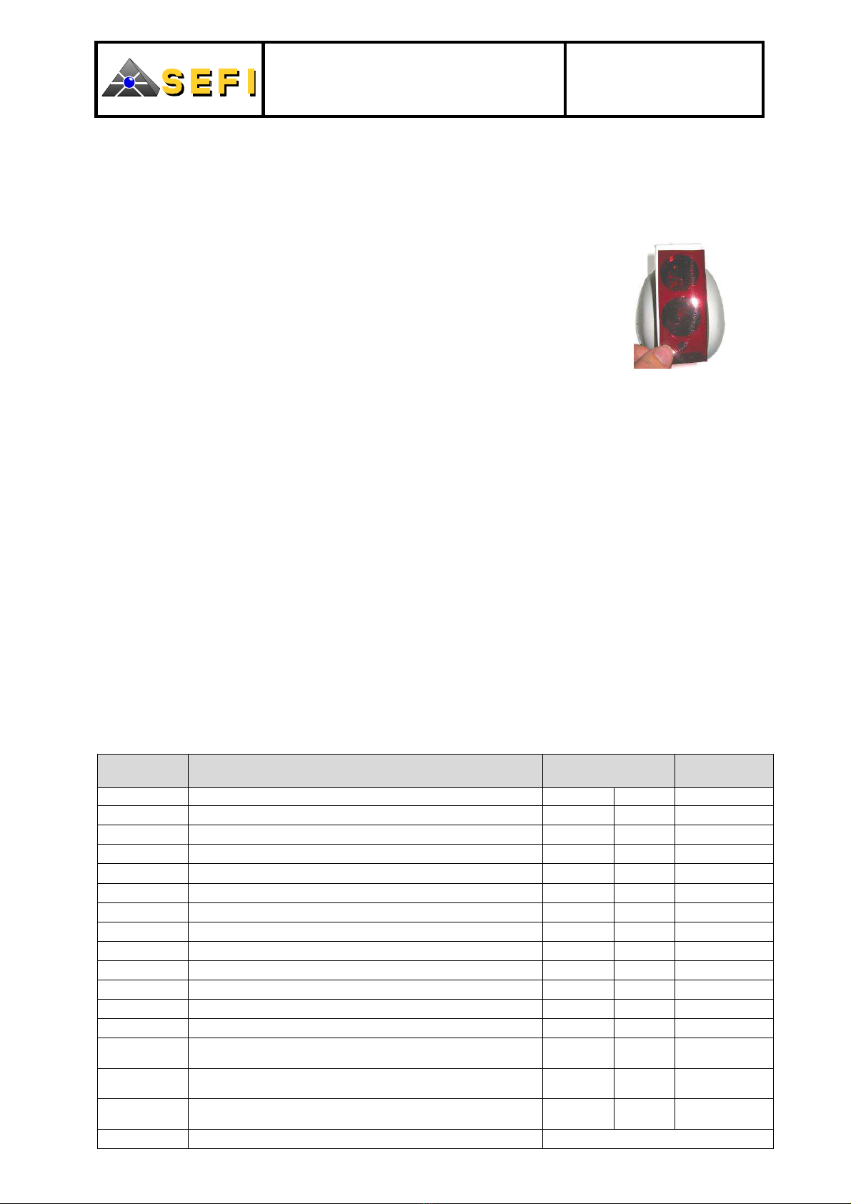
C.3.3. Fire alarm test
That test allows to check that the detector switches properly to fire alarm with the use of the fire alarm
simulation filter
The test procedure is as follows:
The detector has been on standby for at least 1 min ;
Place the fire alarm filter provided in the package right before the
2 lenses of the detector for at least 30 sec (See Figure 11) ;
After that time, the indicator light switches to steady red + superimposed
flash to show the fire alarm condition ;
Remove the fire alarm filter ;
Reset the CIE.
Note
1
:
That test in no way replaces real and regulatory tests.
Note
2
:
Take all required precautions not to trigger an unwanted evacuation
or start off the actuators.
Figure 11: Plac
ing the fire alarm
simulation filter
D. ADVANCED SETTING
D.1. FUNCTIONAL PARAMETERS
The table below lists the level 2 “button codes” for the setting of the DLFBe.
To change one of the parameters, the procedure is as follows:
•At one second intervals, press the buttons to dial the desired code ; each pressing is confirmed by a
green flash emitted by the indicator light ;
•When the code is property entered, the signal emitted by the indicator light is the one mentioned in
the « validation » column ;
•To exit the programming at any time, press the « C » key.
The sequence of 3 green, yellow and red pulses means either:
– That the entry is wrong ;
– The entering time is exceeded ;
– The requested setting is not accepted.
In all cases, the detector switches back to normal operation without changing the setting.
Note: In the event of a power cut on the detector, it keeps the last parameters that were entered.
Code Function
V
isual indicator
confirmation
Works
setting
Green Red
CB AAAA
Return to « works
» settings 1 1
CB AAAB
Sensitivity: minimum 1 2 Yes
CB AABA
Sensitivity: medium 1 3
CB AABB
Sensitivity: maximum 1 4
CB ABAA
Alarm locked 2 1 (1) (5)
CB ABAB
Alarm delayed for 15 sec 2 2 (1) (2) (3) (5)
CB ABBA
Low / high power of calibration beam 2 3 (4)
CB ABBB
Key activation / deactivation 2 4 (6)
CB BAAA
Faults in alarm relay 3 1 (1) (2)
CB BAAB
Faults in fault relay 3 2 Yes (1)
CB BABA
Fault emulation 3 3
CB BABB
Fire alarm emulation 3 4
CB BBAA
Fault filtering: 50 sec
Dazzle filtering: 50 sec 4 1 Yes
CB BBAB
Fault filtering: 250 sec
Dazzle filtering: 250 sec 4 2 (2)
CB BBBA
Fault filtering: unchanged
Dazzle filtering: 900 sec 4 3 (2)
CB BBBB
Visualisation of active configuration See § D.2

DLFBe MANUAL
DLFB (I) DLFB (A),
DLFB (C), DLFB (R)
Document: 26.NGP.1187
Revision: J
Date: 17/03/2010
Page: 11/16
Note (1): This setting only concern the relay version.
Note (2): These settings are not compatibles with the NF mark requirements.
Note (3): Automatic resetting of the alarm after the time indicated when the alarm cause is no longer
detected.
Note (4): In Relay version, the default power of the calibration beam is high. In all other versions, the
default power is low. In conventional, the use of the configuration may switch the connected CIE to alarm.
Note (5): The default parameter (« works setting ») depends on the version that is marketed.
Note (6): The key is activated by default
D.2. VISUALISATION OF ACTIVE CONFIGURATION
To note the current configuration, the procedure is as follows:
At one second interval, press the keys to dial the code « CB BBBB »
Note the sequence of green and red pulses and compare it with the table below.
Note 1: Each sequence starts with a green pulse.
Note 2: The number of red pulses that follows a green pulse provides the status of the configuration in
the sequence.
Sequence Signal interpretation
Start 1 long green pulse Start of sequence
10 short green pulses Start of interactive detector sequence
Sensitivity 1 red pulse Minimum sensitivity
2 red pulses Meidum sensitivity
3 red pulses Maximum sensitivity
Fault filtering
1 red pulse Fault: 50
sec
Dazzle: 50
sec
2 red pulses Fault: 50
sec
Dazzle: 900
sec
3 red pulses Fault: 250
sec
Dazzle: 250
sec
4 red pulses Fault: 250
sec
Dazzle: 900
sec
Alarm relay (3) 1 red pulse Alarm locked
2 red pulses Alarme delayed
Fault relay (3) 1 red pulse Fault in fault relay
2 red pulses Fault in alarm relay
Power of calibration
beam 1 red pulse Low
2 red pulses Strong
Key management 1 red pulse Disactivated key
2 red pulses Activated key
Note (3): This configuration is pointless other than for the relay version
Note 4: The use of the DETTEL allows to read the active configuration textually.
D.3. FIRE ALARM EMULATION
This test allows to put the linear smoke detector in fire alarm condition, without sending the alarm to the
CIE.
The test procedure is as follows:
•At one second intervals, press the push buttons to dial the « CB BABB » code to activate the fire
alarm emulation
•After 3 seconds of measuring the indicator light comes on for 10 sec:
In steady red + superimposed flash in case of success
In steady yellow + superimposed flash in case of fault
That test is automatically exited in less than 30 sec.
Note 1: That fire alarm emulation cannot be triggered if the distance between the optical block and the
reflector is less than 15 m. In that case, an error signal is immediately sent for 10 sec.
Note 2: That fire alarm emulation does not replace real and regulatory fire tests.

DLFBe MANUAL
DLFB (I) DLFB (A),
DLFB (C), DLFB (R)
Document: 26.NGP.1187
Revision: J
Date: 17/03/2010
Page: 12/16
D.4. FAULT EMULATION
This test is used to put the linear smoke detector in fault condition, without however sending such fault to
the CIE.
The test procedure is as follows:
•At one second intervals, press the buttons to dial the « CB BABA » code to activate the fault
emulation
•After 3 sec of measuring the indicator light
Comes on for 10 sec in steady yellow + superimposed flash, in case of success
Does not come on in case of fault
That test is automatically exited in less than 30 sec.
D.5. RELAY CONTACT SETTING
By default, the position of the contacts for the DLFBe Relay version is:
•« NC » for the fault. The contact of the fault relay is « NC » (Normally Closed) in standby condition. In
fault condition, the relay is not active (« NO » contact)
•« NO » for the alarm. The contact of the alarm relay is « NO » (Normally Open) in standby condition.
In alarm condition, the relay is active (« NC » contact).
Note: If the DLFBe relay version is not supplied the fault relay contact is open
It is possible to set the relay contacts using one of the 2 switches located behind the optical block. The
procedure for accessing the switches is as follows:
Remove the cover (See Figure 7)
Unscrew the vertical setting wheel nut without removing it from the screw
Remove the screw from the vertical rotation axis
Remove the optical block from its accommodation
Unclip the holding clip from the top of the optical block and from the optical block back. To do so
press with the 2 thumbs towards the bottom and slip them to the front to release the holding clip (See
Figure 12)
Figure 12: Procedure for access to the 2 switches Figure 13: Drawing of the 2 switches allowing to set the
contacts to alarm and fault relay
After the setting of the relay contacts using 2 switches, reassemble the detector by following these steps:
Assemble the optical block back with the optical block by clipping the upper holding clip in its
accommodation
Insert the optical block in its accommodation
Insert the vertical rotation axis screw in its spot. Screw it in the square nut without tightening
Screw the nut of the vertical setting wheel until the optical block is straight in relationship to the base
plane. Check that the nut is well placed in its spot
Put the cover back.

DLFBe MANUAL
DLFB (I) DLFB (A),
DLFB (C), DLFB (R)
Document: 26.NGP.1187
Revision: J
Date: 17/03/2010
Page: 13/16
E. TECHNICAL FEATURES
MECHANICAL FEATURES
Parameters Features
Space requirement:
•« T/R » installed Width (W): 135,0 mm ; Height (H): 170,0 mm
Depth (D): 160,0 mm
•« T/R » for installation W = 270.0 mm ; H = 210.0 mm ; D = 160.0 mm
•MIR 10 W = 130.0 mm ;H = 100.0 mm ; th = 18.0 mm
•Assembling of 4 MIR 10 W = 230.0 mm ;H = 230.0 mm ; th = 18.0 mm
•Anti-dust cap W = 100.0 mm ; H = 25.0 mm ; th = 2.0 mm
Total weight 1.0 kg 2.2 lb 35.27 oz
Recommended terminal block
screw tightening torque 0.4 m.N
Maximum wire section Terminals 1 to 12: 1 x 2.5 mm
2
Terminals 9: 2 x 2.5 mm2
Vertical setting ± 8°, per setting wheel
Horizontal setting ± 8°, per setting wheel
Casing material Recyclable ABS
Casing colour White – RAL 9016
Protection index IP 31 on whole unit
IP 51 on optical block
OPTICAL FEATURES
Parameters Features
Transmission pulse wavelength 635 nm
Operating distance From 3 m to 100 m
Attenuation of light beam alarm
Minimum Sensitivity (from)
Medium Sensitivity (from)
Maximum Sensitivity (from)
6.0 dB maximum
3.0 dB minimum
2.0 dB minimum
1.0 dB minimum
Approximate time between two slow variation
compensations (fouling, normal air opacity variation,
…)
Attenuation: 20 min
Signal increase: 10 min
Maximum static misalignment of the « T/R » part in
relationship to the optical axis 0.1°
Maximum static misalignment of the orthonormed
axis on reflector plane in relationship to optical axis 0.5°
Maximum tolerance to Transmitter Receiver
(« T/R ») misalignment in relationship to the optical
axis during operation 0.5°
Maximum tolerance to orthonormed axis
misalignment in relationship to reflector plane to the
optical axis 0.5°
Visualisation angle of the alarm indicator light Red light, 30°
Display angle of the fault indicator light Yellow light, 30°
FEATURES ELECTRIQUES
Parameters Features
Power supply From 12 Vdc to 30 Vdc
Relay DLFBe consumption upon
start-up (cold) Rated under 24 Vdc:
35.0 mA maximum for 25 ms
Addressable or conventional DLFBe
consumption upon start-up (cold) Rated under 24 Vdc:
25.0 mA maximum for 15 ms
Relay DLFBe consumption
Standby
Alarm
Fault
Calibration mode
target mode
Rated under 24 Vdc:
15.0 mA
25.0 mA
5.0 mA
45.0 mA
15.0 mA
Addressable or conventional DLFBe
consumption
Standby
Alarm
Fault
Calibration mode
target mode
Rated under 24 Vdc:
adr.: 2.8 mA
adr.: 4.5 mA
adr.: 4.5 mA
adr.: 22.0 mA
adr.: 5.0 mA
conv.: 2,8 mA
conv.: 27,0 mA
conv.: 2,8 mA
conv.: 22,0 mA
conv.: 5,0 mA
Variation in consumption based on
supply power Under 12 Vdc: -5% of rated consumption
Under 30 Vdc: +7% of rated consumption
Current of « test voltage output » Near 0 mA, cannot be used other than for
voltage measuring
Status upon start up Powering up: standby after 15 sec
« Conductive part / ground » link None
Terminals on same potential None
Admissible current and properties by
relay contact (relay version only) Alarm: 1 NO or 1 NF ; 10 mA under
30 Vdc.
Fault: 1 NO or 1 NF ; 10 mA under
30 Vdc.
Alarm relay
(Relay version only) Default: NO position (Normally Open)
Fault relays
(Relay version only) Default: NF position (Normally Closed)
ENVIRONMENT FEATURES
Parameters Features
Operating temperature From -10°C to +55°C
From +14°F to +131°F
Storage temperature From +8°C to +50°C
From +46.4°F to +122°F
Admissible relative Humidity ≤+95% without condensation
FEATURES OF ISOLATOR (ICC)
Parameters Features
Type of short-circuit isolator Single and « controllable » isolator
Loop supply voltage V
max
= 30 Vdc ; V
nom
= 24 Vdc ; V
min
= 12 Vdc
Maximum current I
C max
= 350 mA ; I
S max
= 1 A ; I
L max
= 100 µA
Maximum Impedance Z
C max
= 8 Ω, switch closed
ICC opening voltage
V
SO max
= 5,9 V ;
V
SO min
= 0 V
Connection voltage
V
SC max
= 10 V ;
V
SC min
= 5,9 V
DLFBe MANUAL
DLFB (I) DLFB (A),
DLFB (C), DLFB (R)
Document: 26.NGP.1187
Revision: J
Date: 17/03/2010
Page: 14/16
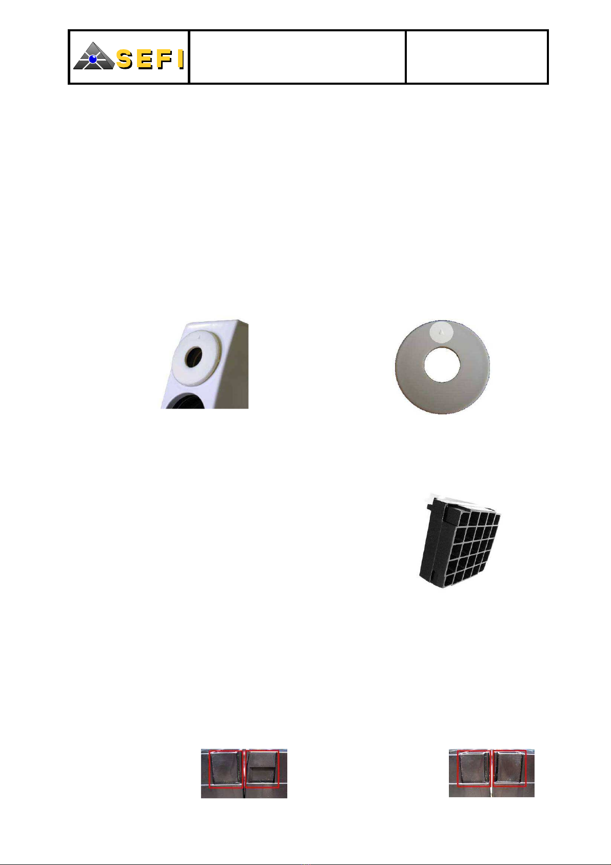
F. INSTALLATION OF OPTICAL ACCESSORIES
F.1. EXTERNAL DIAPHRAGM
Refer to § B.4.3 prior to using the external diaphragm.
In case the detector is used in a highly intense environment, it is necessary to use the external diaphragm
that reduces the dazzle phenomenon.
If the detector is dazzled in operating mode, it switches to fault. The detector returns to its standby
condition after the dazzle disappears.
Positioning of external diaphragm:
•Position the external diaphragm in front of the receiving lens (optics of top of product) (See Figure 14)
•Orient the diaphragm so the engraved triangle is towards the top (See Figure 15)
•Push the diaphragm into the receiving spot until a clip sound is heard.
Note 1: After installing the diaphragm, the detector should be calibrated again
Note 2: To remove the external diaphragm from its spot, pull it to the back from on top
Figure 14: Diaphragm placed in front of the Receiver
of the optical block. Figure 15: External diaphragm with its engraved triangle
The use of the external diaphragm can include an increase in the reflector surface area (See § G).
F.2. SUNSHIELD
Refer to § B.4.3 before using the sunshields.
Application conditions:
The sunshield on the reflector (See Figure 16) protect the
detection system in the event the angle between the interfering
light rays and the optical axis of the reflector (axis perpendicular
to the reflecting side of the reflector) is over 40°.
It is possible to superimpose 2 sunshields. Such an assembling
protects the detection system in the event the angle
between the
interfering light rays and the optical axis of the reflector ranges
from 20°to 40°.
Figure 16: Sunshield
Note 1: When there are 2 layers of sunshields, it is vital to place the optical block on the optical axis of
the reflector.
Note 2: If the interfering sun rays reach the section of the reflector, it should be protected by matt black
film.
Fastening the sunshields:
A sunshield is fastened on a reflector using clips. When using a reflector made up of several reflectors,
mount the sunshields on the reflectors before assembling the whole unit.
To assemble several items, orient the sunshields to reduce the space between 2 reflectors (See
Figure 17 and Figure 18).
PROPER MOUNTING
IMPROPER MOUNTING
Figure 17: Side view. The
side shape alternates
Figure 18: Side view. The side
shape does not alternate.

DLFBe MANUAL
DLFB (I) DLFB (A),
DLFB (C), DLFB (R)
Document: 26.NGP.1187
Revision: J
Date: 17/03/2010
Page: 15/16
G. SELECTION OF NUMBER OF REFLECTORS
The table below shows the number of reflectors to be used based on distance and optical accessories:
DISTANCE WITHOUT ACCESSORIES WITH ACCESSORIES
From 3 m to 40 m 1 1
From 40 m to 60 m 2 4
From 60 m to 80 m 4 9
From 80 m to 100 m 9 16
H. RECYCLING
All components of the linear smoke detector must comply with the
recycling prescriptions of Directive 2002/96/CE of the European
Parliament and Council dated January 27, 2003, relating to
Electrical and Electronic Equipment Waste (DEEE). They must not
be discarded (See Figure 19)
Figure 19: Information pictogram
I. WARRANTY LIMITATION
The legal manufacturer warranty applies to this product. However, it is limited to a normal use of the
product in compliance with these instructions. It ends of these instructions are not complied with, the
lenses are damaged, the product is disassembled (including tampering with the opening check
chip), terminal blocks are damaged, and the link cable (between the optical block and the wall
mounting) is damaged, after the legal period.
J. MARKING
0333
SEFI
Rue René Cassin
PB 90817
45308 PITHIVIERS cedex FRANCE 07
0333 CPD075 019
EN 54-12: 2002 line detectors using an optical light
beam
EN 54-17: 2005 short-circuit isolators
Fire detection and fire alarm systems
Instructions: 26.NGP.1187
G205146

DLFBe MANUAL
DLFB (I) DLFB (A),
DLFB (C), DLFB (R)
Document: 26.NGP.1187
Revision: J
Date: 17/03/2010
Page: 16/16
INSTALLATION AND STARTING UP SHEET
This sheet describes the main steps to be completed to install and start up the detector
1 Estimate the distance between the detector and the reflector
2 Is the detector exposed to direct sunlight (See B.4.3) ?
If Yes, change the intended location of the detector
3 Is the reflector exposed to directly sunlight (See B.4.3) ?
If Yes, change the intended location of the detector
4 Is the luminous environment (diffusion of natural light, interfering reflexions …)
very intense ?
If Yes, use the optical accessories
5 Determine the number of MIR10s to be installed based on
the answers to steps 1 and 4 (See G)
6 In the event optical accessories are used, clip the sunshields
to the MIR10 (See F.2) before assembling them
7 Is the space requirement of the detector for its installation
compatible with the intended location (See B.5.1) ?
If No, change the intended location of the detector
8 Is the space requirement of the detector compatible with the intended location (See B.5.2) ?
If No, change the intended location of the detector
9 Install the detector (See B.6.1) according to mechanical installation rules (See B.4.2)
10 Install the reflector (See B.6.2) according to mechanical installation rules (See B.4.2)
11 Complete the electrical connection of the detector (See B.7)
12 Turn on the detector (See C.1.2)
The DETTEL supplies the detector in the event the ECS is not connected (use of the DETTEL)
13 Carry out the calibration of the detector (See C.2)
Is the calibration exit correct ?
If No, do the calibration again
14 Note the recorded gain value and check that it is under 200. If not, resume the installation
from step 13 (use of DETTEL)
15 If optical accessories are used (See B.4.3), clip the external diaphragm
to the receiving lens (upper lens) of the detector (See F.1). In that case,
calibrate the detector again
16 Perform a target test (See C.3.1)
Is the visual indicator green when the whole reflector surface covered ?
If No, check that the detector is indeed aligned on the reflector (resume the installation
from step 13 as needed) and check that there is no interfering reflexion
on the beam route (cable tray, metal beams…)
17 Perform a fire alarm test using the alarm filter provided in the packaging (See C.3.3)
Is the detector switched to fire alarm after the specified time ?
If No, resume the installation from step 13
18 Reset the ECS or the detector (case of Relay version) to clear the fire alarm condition.
19 Set the time on the detector (use of the DETTEL)
20 Delete the history (use of the DETTEL)
This manual suits for next models
4
Table of contents


