INSTRUCTION
Read this instruction before installation
and wiring of the product
SDD-S65(-RAC) and SDD-OE65(-RAC)
Consult documentation in all cases where this symbol
is used, in order to nd out the nature of the potential
hazards and any actions to be taken
1
SDD-S65(-RAC) and SDD-OE65(-RAC)
Smoke detector for duct mounting
The detectors come in two dierent types: one optical (SDD-OE65...)
and one ionisation (SDD-S65...). Both types are available with or
without relay.
Function
The detector is connected to the control unit ABV... with a two-wire
loop. The last detector in the loop is connected to the end resistor
supplied together with the control unit to provide a closed signal loop.
The RAC models have a relay and are not to be connected to Regin’s
control units ABV... The built-in relay makes it possible for the unit to
independently give an alarm without connection to a control unit.
The detector housing has a window giving a clear view of the ow
indicator and the alarm LED. The LED lights up when there is a re
alarm, but is normally o.
The detectors have a built-in service alarm function for sensing the dust
and dirt accumulation which inevitably occurs over time. When the degree
of dirt has reached the level at which there is the risk of false alarms, a
service alarm is given indicating that cleaning is required. This is indicated
by a red LED on the detector and by a yellow LED on the connected
control unit, type ABV-S-300/D or ABV24-S-300/D.
Installation
The detector should be mounted at least three duct widths away from duct
bends and fresh air inlets.
The holder is designed so that it will also t directly onto round ducts.
1. Drill the required hole for the venturi tube in the duct (Ø 30 mm).
2. Remove the housing lid and remove the detector head which is
bayonet mounted.
3. Mount the venturi tube by removing the screw from the tube’s
unclosed end, stick the end of the tube into the hole in the bottom
of the housing with the holes in the tube aligned with the housing’s
longitudinal axis. Fasten the screw through the hole in the PC-board.
4. Replace the detector head.
5. Temporarily replace the lid oriented so that the LED on the detector
head is visible through the window. Put the tube through the hole in
the duct, orient the unit so that the arrows on the lid point in the ow
direction (see gure 1).
6. Fasten the unit to the duct using the mounting ”wings”. For round
ducts the wings can be bent to t the duct curvature. For insulated
ducts, the mounting plateTDS is available as an extra accessory.
Flow
Figure 1. Flow direction
The venturi tube has lips that match the tube holder on the housing.
The venturi tube can be shortened for smaller ducts by removing the end-
plate and gasket from the tube’s outer end, shorten the tube making sure
to cut it at a right angle, and remount the gasket and plate. Check the ow
indicator after re-installation to make sure there is air ow to the detector.
For larger ventilation ducts, a longer venturi tube can be ordered.
When the detector has to be mounted at a distance from the duct
(e.g. when insulation material is used) the mounting plate TDS should
be used. A distance bushing for mounting on the venturi tube is deliv-
ered with the mounting plate.
Wiring
SDD-S65 and SDD-S65-OE
The detector is wired to the control unit through a two-wire current
loop. The loop is closed by connecting the supplied 2.2 kΩ end
resistor.
If the loop contains more than one detector the end resistor should
only be mounted in the last detector in the loop. If the loop lacks an
end resistor or if there is more than one resistor, the control unit will
give an alarm.
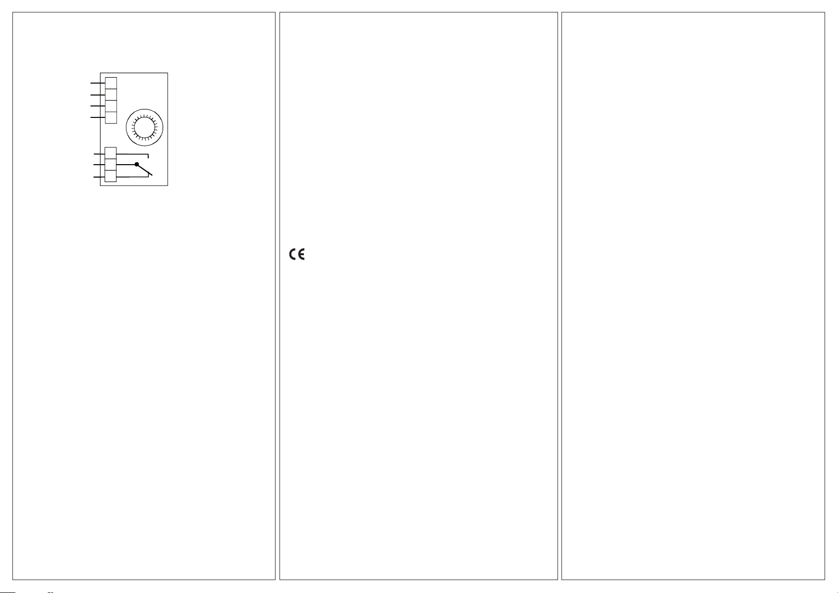
Wire the detector according to the wiring diagram below:
1
2
3
4
5
7
8
9
10
11
12
ABV...
SDD...
SDD...
1
2
3
4
5
1
2
3
4
5
6
Figure 2. Wiring SDD-S65 and SDD-S65-OE to ABV...
Note: -RAC models should not be mounted in loop or to a control unit
13112A
JUL17
EN
End resistor 2.2 kΩ
(delivered with ABV...)