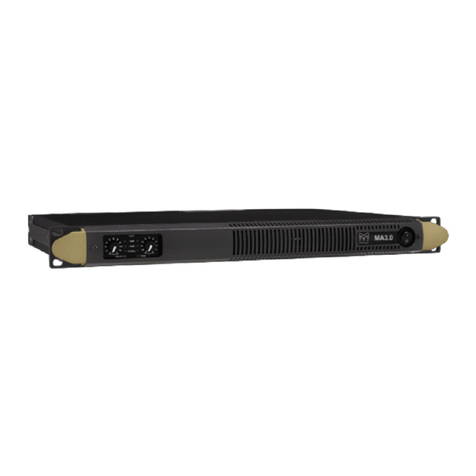
Segon AME-120-4Z User manual

NOTICE D’UTILISATION
SÉRIE AME
AMPLIFICATEURS MELANGEURS
AME-120/240/360-4Z
5 Rue d'Apollo PA de Montredon 31240 L'UNION- FRANCE

FRANÇAIS
Nous vous remercions d’avoir acheté un produit SEGON PROFESSIONAL AUDIO. Veuillez lire la présente notice avant
l’utilisation afin de pouvoir en profiter pleinement.
Veuillez lire la notice avant toute utilisation. Respectez impérativement les instructions afin de continuer à bénéficier de la
garantie. Prenez toutes les précautions nécessaires pour éviter tout incendie ou décharge électrique. Seul un technicien
spécialisé peut effectuer les réparations. Nous vous conseillons de conserver la présente notice pour pouvoir vous y reporter
ultérieurement.
-Avant d’utiliser l’appareil, prenez conseil auprès d’un
spécialiste. Lors de la première mise sous tension, il est
possible qu’une odeur soit perceptible. C’est normal,
l’odeur disparaîtra peu de temps après.
-L’appareil contient des composants porteurs de tension.
N’OUVREZ JAMAIS le boîtier.
- Ne placez pas des objets métalliques ou du liquide sur
l’appareil, cela pourrait causer des décharges électriques
et dysfonctionnements..
-Ne placez pas l’appareil à proximité de sources de
chaleur, par exemple radiateur. Ne positionnez pas
l’appareil sur une surface vibrante. N’obturez pas les
ouïes de ventilation.
-L’appareil n’est pas conçu pour une utilisation en
continu.
- Faites attention au cordon secteur, il ne doit pas être
endommagé.
-Lorsque vous débranchez l’appareil de la prise secteur,
tenez-le par la prise, ne tirez jamais sur le cordon.
- Ne branchez pas et ne débranchez pas l’appareil avec
les mains mouillées.
- Seul un technicien spécialisé peut remplacer la fiche
secteur et / ou le cordon secteur.
-Si l’appareil est endommagé et donc les éléments
internes sont visibles, ne branchez pas l’appareil, NE
L’ALLUMEZ PAS. Contactez votre revendeur.
-Pour éviter tout risque d’incendie ou de décharge
électrique, n’exposez pas l’appareil à la pluie ou à
l’humidité.
- Seul un technicien habilité et spécialisé peut effectuer les
réparations
-Branchez l’appareil à une prise secteur 220-240 Vac/50
Hz avec terre, avec un fusible 10-16 A.
- Pendant un orage ou en cas de non utilisation prolongée
de l’appareil, débranchez l’appareil du secteur.
-En cas de non utilisation prolongée de l’appareil, de la
condensation peut être créée. Avant de l’allumer, laissez
l’appareil atteindre la température ambiante. Ne l’utilisez
jamais dans des pièces humides ou en extérieur.
-Afin d’éviter tout accident en entreprise, vous devez
respecter les conseils et instructions.
-N’allumez pas et n’éteignez pas l’appareil de manière
répétée. Cela réduit sa durée de vie.
-Conservez l’appareil hors de la portée des enfants. Ne
laissez pas l’appareil sans surveillance.
-N’utilisez pas d’aérosols pour nettoyer les interrupteurs.
Les résidus créent des dépôts et de la graisse. En cas
de dysfonctionnement, demandez conseil à un
spécialiste.
- Ne forcez pas les réglages.
-Si l’accumulateur est endommagé, remplacez-le par un
accumulateur de même type et déposez l’ancien
accumulateur dans un container de recyclage adapté.
- Si l’appareil est tombé, faites-le toujours vérifier par un
technicien avant de le rallumer.
-Pour nettoyer l’appareil, n’utilisez pas de produits
chimiques qui abîment le revêtement, utilisez
uniquement un tissu sec.
-Tenez toujours l’appareil éloigné de tout équipement
électrique pouvant causer des interférences.
- Pour toute réparation, il faut impérativement utiliser des
pièces d’origine, sinon il y a risque de dommages graves
et / ou de radiations dangereuses.
-Eteignez toujours l’appareil avant de le débrancher du
secteur et de tout autre appareil. Débranchez tous les
cordons avant de déplacer l’appareil.
- Assurez-vous que le cordon secteur n’est pas abîmé si
des personnes viennent à marcher dessus. Avant toute
utilisation, vérifiez son état.
-La tension d’alimentation est de 220-240Vac/50 Hz.
Vérifiez la compatibilité. Si vous voyagez, vérifiez que la
tension d’alimentation du pays est compatible avec
l’appareil.
-Conservez l’emballage d’origine pour pouvoir transporter
l’appareil en toute sécurité.
Ce symbole doit attirer l’attention de l’utilisateur sur les tensions élevées présentes dans le boîtier de l’appareil, pouvant
engendrer une décharge électrique.
Ce symbole doit attirer l’attention de l’utilisateur sur des instructions importantes détaillées dans la notice, elles doivent
être lues et respectées.
Cet appareil porte le symbole CE. Il est interdit d’effectuer toute modification sur l’appareil. La certification CE et la garantie
deviendraient caduques !
NOTE: Pour un fonctionnement normal de l’appareil, il doit être utilisé en intérieur avec une plage de température maximale
autorisée entre 5°C/41°F et 35°C/95°F.
Ne jetez pas les produits électriques dans la poubelle domestique. Déposez-les dans une décharge. Demandez conseil aux autorisés
ou à votre revendeur. Données techniques réservées. Les valeurs actuelles peuvent varier d’un produit à l’autre. Tout droit de
modification réservé sans notification préalable.
N’essayez pas de réparer l’appareil vous-même. Vous perdriez tout droit à la garantie. Ne faites aucune modification sur l’appareil. Vous
perdriez tout droit à la garantie La garantie deviendrait également caduque en cas d’accidents ou dommages causes par une utilisation
inappropriée de l’appareil ou un non respect des consignes présentes dans cette notice. SEGON PROFESSIONAL AUDIO ne pourrait
être tenu responsable en cas de dommages matériels ou corporels causés par un non respect des consignes de sécurité et
avertissements. Cela est également valable pour tous les dommages quelle que soit la forme.

DÉBALLAGE
ATTENTION ! Immédiatement après réception, vérifiez le contenu du carton et assurez-vous que tous les éléments sont bien
présents et en bon état. Si besoin, faites les réserves nécessaires si le matériel ou les cartons sont endommagés. SI l’appareil
doit être retourné, faites-le dans l’emballage d’origine.
Si l’appareil a été exposé à des fluctuations importantes de températures (par exemple après le transport), ne l’allumez pas
immédiatement. De la condensation peut survenir. Laissez l’appareil éteint le temps qu’il atteigne la température ambiante.
ALIMENTATION
Vous trouvez sur l’étiquette à l’arrière de l’appareil, le type d’alimentation à utiliser. Vérifiez que la tension d’alimentation
corresponde à celle mentionnée. Toute autre alimentation peut endommager l’appareil. Reliez l’appareil au secteur, il est prêt à
être utilisé. En aucun cas, vous ne devez utiliser de dimmer ou d’alimentation réglable.
Connectez toujours l'appareil à un circuit protégé (disjoncteur ou fusible). Assurezvous que l'appareil soit correctement
relié à la terre afin d'éviter tout risque d'électrocution ou d'incendie
SYSTEME LIGNE 100 V
Pour des systèmes ligne 100 V, reliez l’amplificateur au premier haut-parleur dans le système en utilisant un câble haut-parleur
à double isolation ayant la puissance adéquate pour supporter la sortie totale de l’amplificateur.
Reliez la borne de sortie “100V“ à la borne (+) du haut-parleur et la sortie “COM“ à la borne (-). Reliez d'autres haut-parleurs en
parallèle au premier haut-parleur avec tous les borniers positifs ensemble et reliez tous les borniers négatifs ensemble comme
indiqué sur le schéma.
Exemple
Un système ligne 100 V peut se compose de plusieurs haut-parleurs reliés entre eux. Le facteur permettant de définir le nombre
de haut-parleurs pouvant être reliés à un seul amplificateur est la puissance. Pour la majorité des applications, il est conseillé
de relier autant de haut-parleurs que nécessaire avec une puissance combinée de 90% au plus de la puissance de sortie de
l'amplificateur.
Les bornes d'un haut-parleur 100 V sont reliées à un transformateur et dans certains cas, ce transformateur peut être utilisé
pour différentes puissances. Ces réglages peuvent être utilisés pour régler la puissance (et le volume de sortie) de chaque
haut-parleur dans le système pour obtenir la puissance totale idéale du système pour l'amplificateur.
BORNIERS HP
Ces bornes offrent une sortie basse tension 8Ω et une sortie 100V est également disponible.
Notez qu'un câble uniquement doit être connecté à la borne COM et un câble à l'impédance ou tension sélectionnée.
ATTENTION : Il n'est pas possible de faire des combinaisons multiples sur le niveau de sortie.
Deux types différents de branchement sont prévus.
Section basse impédance 8Ω: prévue pour une petite quantité de haut-parleurs pouvant être reliés à l'amplificateur
Section 100V : spécifiquement conçue pour une distribution multiple. Si vous utilisez la sortie 100W, les haut-parleurs doivent
être équipés d'un transformateur 100V. La quantité maximale de haut-parleurs à intégrer dans le système est fonction de la

puissance délivrée par chaque haut-parleur. La puissance totale réglée sur le côté secondaire des transformateurs de la ligne
de haut-parleurs ne doit pas dépasser la puissance de sortie RMS maximale. Un non-respect de ces données pourrait
endommager durablement l'amplificateur.
ETAPES DE FONCTIONNEMENT
•Lorsque toutes les connexions à l'amplificateur sont effectuées, tournes les boutons de réglage vers le minium et allumez
l'amplificateur, la LED “ON“ brille. Tournez les réglages BASS et TREBLE vers la position 12h (vers le haut) et tournez le
réglage MASTER pour tester.
•Assurez-vous qu'un signal est bien présent aux entrées ligne et augmentez graduellement le niveau de volume pour ce
canal jusqu'à ce que la sortie soit bien audible via les haut-parleurs. Tournez le réglage MASTER sur le niveau de volume
maximal nécessaire et diminuez le niveau de volume du canal si besoin.
•Remarque : le test initial peut être effectué en utilisant le lecteur audio USB/SD intégré. La sortie de l'amplificateur est
représentée sur le VU-mètre ; veillez à ce que la LED rouge “0“ ne brille que momentanément pendant le fonctionnement.
Si elle brille plus longtemps, cela indique qu'il y a une distorsion ou un écrêtage du signal de sortie : tournez alors le
réglage MASTER pour diminuer le niveau.
•Si un microphone est relié à l'entrée MIC1, assurez-vous qu'il est bien allumé et s'il nécessite une alimentation fantôme,
prêtez y attention. Augmentez petit à petit le volume en parlant dans le microphone jusqu'à obtenir le niveau de volume
souhaité. Le microphone ne doit pas entendre les haut-parleurs pour éviter tout effet de larsen.
En plus des réglages de canaux et de volume MASTER, l'appareil dispose de réglages BASS et TREBLE EQ pour régler la
tonalité de la sortie générale. Sur la position 12h, ces réglages n'influent pas sur le signal. Si vous déplacez le réglage BASS
dans le sens des aiguilles d'une montre, les fréquences graves augmentent ; si vous le tournez vers la gauche, il réduit les
fréquences graves. De la même manière, si vous tournez le réglage TREBLE vers la droite, vous augmentez les fréquences
aigues dans l'audio, si vous le tournez vers la gauche, vous diminuez ces fréquences. Réglez les égaliseurs pour correspondre
au type de signal audio ou pour compenser l'acoustique de la pièce.
REMPLACEMENT DU FUSIBLE
Si le fusible est défectueux, il faut le remplacer par un fusible de même type et de même valeur. Avant de le remplacer, veillez à
débrancher l’appareil.
Procédure:
Etape 1: Ouvrez le porte-fusible sur le panneau arrière avec un petit tournevis.
Etape 2: Retirez l’ancien fusible.
Etape 3: Placez le nouveau fusible dans le porte-fusible.
Etape 4: Remettez le porte-fusible dans le boîtier.
REGLAGES ET BRANCHEMENTS
Face Avant:
1. AFFICHAGE LCD
Affichage des modes de fonctionnement et du statut actuel.
2. PORT USB
Port pour brancher un support de stockage USB. Les morceaux présents sur le support sont lus par le lecteur et démarrent
automatiquement lorsque le support est inséré.

3. INSERT CARTE MEMOIRE SD / MMC
Insert pour des cartes mémoires SD/MMC. Les morceaux présents sur le support sont lus par le lecteur et démarrent
automatiquement lorsque le support est inséré.
4. TOUCHE SKIP I<<
Voie précédente en mode USB, SD/MMC ou BT. Station précédente si l’appareil est en mode Tuner.
5. TOUCHE PLAY / PAUSE
A chaque pression sur la touche PLAY/PAUSE, l’appareil passe du mode lecture au mode pause et du mode pause au
mode lecture.
6. TOUCHE SKIP >>I
Voie suivante en mode USB, SD/MMC ou BT. Station suivante si l’appareil est en mode Tuner.
7. TOUCHE REPEAT
Pour activer la fonction Répétition : répétition d’une voie, du dossier complet, répétition de toutes les voies et fonction
désactivée.
8. TOUCHE +
Pour augmenter le volume du lecteur.
9. TOUCHE -
Pour diminuer le volume du lecteur.
10.TOUCHE M
Pour commuter le mode de fonctionnement entre USB, SD/MMC, BT et Tuner.
11.TOUCHE POWER ON / OFF
Enfoncée : pour allumer le lecteur.
Enfoncée et maintenue : pour éteindre le lecteur.
12.REGLAGE VOLUME MICROPHONE 1 & 2
Pour augmenter et diminuer le volume de l’entrée micro 1 et 2.
13.REGLAGE VOLUME MICROPHONE 3 & LINE 1
Pour augmenter et diminuer le volume de l’entrée micro 3 ou ligne 1.
14.REGLAGE ECHO MICROPHONE
Pour régler le niveau d’écho des canaux micro.
15.REGLAGE VOLUME LINE 2 & 3
Pour augmenter et diminuer le volume de l’entrée ligne 2 & 3.
16.REGLAGE TONALITE
Boutons de réglage des graves et aigus ; en tournant vers la droite, le niveau est augmenté, vers la gauche, le niveau est
diminué. En position centrale, les deux réglages sont neutres.
17.REGLAGE VOLUME MASTER
Réglage du volume général entre niveau minimal et niveau maximal.
18.VU-METRE A LEDS
Bargraphe 6 LEDs ; indique le niveau actuel dans la plage -18 dB et 0 dB, la LED supérieure rouge s’affiche en cas
d’écrêtage.
19.INTERRUPTEURS SORTIE ZONE 1-4
Les différentes lignes (1-4) de haut-parleurs reliés peuvent être activées ou désactivées avec les interrupteurs
correspondants. Si une zone (1-4) est activée, l’interrupteur correspondant s’allume en vert. Lorsque l’interrupteur “All“ est
activé, toutes les sorties de zones (1-4) sont activées.
20.REGLAGE NIVEAU SORTIE ZONE 1-4
Le niveau de sortie des zones (1-4) peut être réglé avec les interrupteurs correspondants.
21.INTERRUPTEUR TOUTES ZONES
Lorsque l’interrupteur “All“ est activé, toutes les sorties de zones (1-4) sont activées.
22.INTERRUPTEUR CHIME
Lorsque l’interrupteur CHIME est enfoncé, le gong sélectionné pour signaler une annonce retentit une fois.
23.INTERRUPTEUR FIRE
Lorsque l’interrupteur est enfoncé, l'alarme incendie passe à travers la boucle jusqu'à ce que l’interrupteur d'incendie soit
enfoncé à nouveau.
24.INTERRUPTEUR POWER ON / OFF
Pour allumer l’appareil et pour l’éteindre. L’interrupteur brille en vert lorsque vous allumez l’appareil. Le buzzer interne
retentit trois fois et le relais de protection de sortie s’active (un clic est alors audible), l’appareil est alors prêt.

Face Arrière:
1. PRISE SECTEUR DC
Prise d’alimentation DV (24 V) pour brancher une batterie standard 24 V. Un porte-fusible pour le fusible principal est situé
sur le haut de la prise (voir point “Remplacement du fusible“ pour les instructions de remplacement du fusible).
2. PRISE SECTEUR AC
Prise d’alimentation AC 230~240V AC / 50~60 Hz) . Un porte-fusible pour le fusible principal est situé sur le haut de la prise
AC (voir point “Remplacement du fusible“ pour les instructions de remplacement du fusible).
3. ANTENNE FM
Pour pouvoir utiliser la fonction radio FM, dépliez l’antenne pour une réception FM optimale.
4. SORTIES (RCA)
Prises pour agrandir l’installation en ajoutant un second amplificateur. Reliez l’entrée LINE2 ou LINE3 du second
amplificateur à cette prise “OUT“.
5. ENTREES LIGNE 2 & 3 ASYMETRIQUES (RCA)
Prises d’entrée ligne 2 & 3 , RCA ; peut être transformée en entrée ligne stéréo en branchant la droite au rouge et la gauche
au blanc.
6. BRANCHEMENTS SORTIES (BORNIER)
Prises de sortie pour les systèmes audio à la fois basse impédance et tension constante. Le haut-parleur basse impédance
et la sortie tension constante 100 V partagent un bornier à 4 broches, deux à gauche peuvent être utilisés pour connecter
les haut-parleurs basse impédance, les deux à droite pour les haut-parleurs haute impédance (tension constante 100 V).
Pour les sorties de zone (1-4), un connecteur à 8 broches.
7. ENTREES MIC3 / LINE1, MIC2 & MIC1
Ces canaux utilisent des connecteurs combo, à la fois connecteurs XLR et connecteurs jack 6,35. Les deux configurations
coupent le son de tous les autres canaux lorsqu'un signal est présent sur les microphones/entrées reliés. L’entrée micro 1 et
2 peut être utilisée pour microphones capacitifs. Les interrupteurs d'alimentation fantôme permettent une alimentation
fantôme 15 V si un microphone capacitif est connecté. L’interrupteur 2 alimente l'entrée micro 1 en alimentation fantôme,
tandis que le commutateur 1 alimente l'entrée micro 2 en alimentation fantôme.
8. ENTREE EMERGENCY
L'amplificateur peut être connecté à n'importe quelle sortie d'amplificateur à tension constante de 100 V avec une
télécommande 24 V utilisée comme entrée de secours. Lorsque le signal DC 24V est présent, l'amplificateur commute sur
tous les haut-parleurs connectés (sortie tension constante) pour envoyer le signal d'urgence.
9. ENTREE TEL
L'amplificateur peut être connecté à n'importe quel système de télécommunication à l'aide de l'entrée TEL, ce qui permet de
faire des annonces à partir d'un combiné. C’est une entrée niveau ligne avec priorité. Les branchements d'entrée
asymétriques doivent être faits aux bornes 'CH' (Hot ou Signal) et 'GND' (Ground).
10.ENTREES CHIME & FIRE
Les entrées Gong et Incendie permettent de connecter n'importe quelle source externe telle qu'un poste d'appel, une
matrice de signaux ou un système d'alarme incendie. Ces entrées sont prioritaires sur les autres entrées.
11.ANTENNE BT
Si vous branchez ou utilisez la technologie BT, assurez-vous de régler l'antenne BT en position verticale pour assurer le
meilleur signal sans fil possible.

ENGLISH
Congratulations to the purchase of this SEGON PROFESSIONAL AUDIO product. Please read this manual thoroughly prior
to using the unit in order to benefit fully from all features.
Read the manual prior to using the unit. Follow the instructions in order not to invalidate the warranty. Take all precautions to
avoid fire and/or electrical shock. Repairs must only be carried out by a qualified technician in order to avoid electrical shock.
Keep the manual for future reference.
- Prior to using the unit, please ask advice from a
specialist. When the unit is switched on for the first time,
some smell may occur. This is normal and will disappear
after a while.
- The unit contains voltage carrying parts. Therefore do
NOT open the housing.
- Do not place metal objects or pour liquids into the unit
This may cause electrical shock and malfunction.
- Do not place the unit near heat sources such as
radiators, etc. Do not place the unit on a vibrating
surface. Do not cover the ventilation holes.
- The unit is not suitable for continuous use.
- Be careful with the mains lead and do not damage it. A
faulty or damaged mains lead can cause electrical shock
and malfunction.
- When unplugging the unit from a mains outlet, always
pull the plug, never the lead.
- Do not plug or unplug the unit with wet hands.
- If the plug and/or the mains lead are damaged, they
need to be replaced by a qualified technician.
- If the unit is damaged to such an extent that internal
parts are visible, do NOT plug the unit into a mains outlet
and DO NOT switch the unit on. Contact your dealer.
- To avoid fire and shock hazard, do not expose the unit to
rain and moisture.
- All repairs should be carried out by a qualified technician
only.
- Connect the unit to an earthed mains outlet (220-
240Vac/50Hz) protected by a 10-16A fuse.
- During a thunderstorm or if the unit will not be used for a
longer period of time, unplug it from the mains. The rule
is: Unplug it from the mains when not in use.
- If the unit has not been used for a longer period of time,
condensation may occur. Let the unit reach room
temperature before you switch it on. Never use the unit in
humid rooms or outdoors.
- To prevent accidents in companies, you must follow the
applicable guide lines and follow the instructions.
- Do not repeatedly switch the fixture on and off. This
shortens the life time.
- Keep the unit out of the reach of children. Do not leave
the unit unattended.
- Do not use cleaning sprays to clean switches. The
residues of these sprays cause deposits of dust and
grease. In case of malfunction, always seek advice from
a specialist.
- Do not force the controls.
- If the unit has fallen, always have it checked by a
qualified technician before you switch the unit on again.
- Do not use chemicals to clean the unit. They damage the
varnish. Only clean the unit with a dry cloth.
- Keep away from electronic equipment that may cause
interference.
- Only use original spares for repairs, otherwise serious
damage and/or dangerous radiation may occur.
- Switch the unit off prior to unplugging it from the mains
and/or other equipment. Unplug all leads and cables
prior to moving the unit.
- Make sure that the mains lead cannot be damaged when
people walk on it. Check the mains lead before every use
for damages and faults!
- The mains voltage is 220-240Vac/50Hz. Check if power
outlet match. If you travel, make sure that the mains
voltage of the country is suitable for this unit.
- Keep the original packing material so that you can
transport the unit in safe conditions.
This mark attracts the attention of the user to high voltages that are present inside the housing and that are of sufficient
magnitude to cause a shock hazard.
This mark attracts the attention of the user to important instructions that are contained in the manual and that he should
read and adhere to.
The unit has been certified CE. It is prohibited to make any changes to the unit. They would invalidate the CE certificate and
their guarantee!
NOTE: To make sure that the unit will function normally, it must be used in rooms with a temperature between 5°C/41°F and
35°C/95°F.
Electric products must not be put into household waste. Please bring them to a recycling centre. Ask your local authorities or your
dealer about the way to proceed. The specifications are typical. The actual values can slightly change from one unit to the other.
Specifications can be changed without prior notice.
Do not attempt to make any repairs yourself. This would invalid your warranty. Do not make any changes to the unit. This would also invalid
your warranty. The warranty is not applicable in case of accidents or damages caused by inappropriate use or disrespect of the warnings
contained in this manual. SEGON PROFESSIONAL AUDIO cannot be held responsible for personal injuries caused by a disrespect of the
safety recommendations and warnings. This is also applicable to all damages in whatever form.

UNPACKING INSTRUCTION
CAUTION! Immediately upon receiving the product, carefully unpack the carton, check the contents to ensure that all parts are
present, and have been received in good condition. Notify the shipper immediately and retain packing material for inspection if
any parts appear damage from shipping or the package itself shows signs of mishandling. Save the package and all packing
materials. In the event that the product must be returned to the factory, it is important that the product be returned in the original
factory box and packing.
If the device has been exposed to drastic temperature fluctuation (e.g. after transportation), do not switch it on immediately. The
arising condensation water might damage your device. Leave the device switched off until it has reached room temperature.
POWERSUPPLY
On the label on the backside of the product is indicated on this type of power supply must be connected. Check that the mains
voltage corresponds to this, all other voltages than specified, the light effect can be irreparably damaged. The product must also
be directly connected to the mains and may be used. No dimmer or adjustable power supply.
Always connect the device to a protected circuit (circuit breaker or fuse). Make sure the device has an appropriate
electrical ground to avoid the risk of electrocution or fire.
100V LINE SYSTEM
For 100V line systems, connect the amplifier to the first speaker in the system using double-insulated speaker wire which has
adequate current rating to handle the total output of the amplifier.
Connect the “100V” output terminal to the positive (+) connection of the speaker and “COM” output to the negative (-)
connection of the speaker. Connect further speakers in parallel to the first speaker with all positive terminals and connected
together and all negative terminals connected together as shown below.
Examples
A 100V line speaker system can comprise of many speakers connected together. The determining factor for how many
speakers can be used on a single amplifier is the power rating. For most purposes, it is advised to connect as many speakers
as needed with a combined wattage of no more than 90% of the amplifier’s output power rating.
The terminals of a 100V speaker are connected to a transformer and in some cases, this transformer may be “tapped” for
different power ratings. These tapings can be used to adjust the wattage (and output volume) of each speaker in the system to
help achieve the ideal total power of the system for the amplifier.

SPEAKER TERMINALS
These terminals are offering a low voltage output of 8Ω. A 100V commercial output is also available.
Please note that one wire only should be connected to COM screw and one wire to the selected impedance or voltage.
ATTENTION: Multiple combinations cannot be done at the output level.
Two different types of connections are provided. The low impedance section: 8Ωis designed for a small amount of speakers to
be connected to your amplifier. The 100V section is especially designed for a multiple speaker distribution. When using the
100V output, speakers have to be equipped with a 100V transformer. The maximum amount of speakers to be placed on your
distribution line is in relation to the power allocated to each speaker. The total wattage set on the secondary side of the
transformers on your speaker line must not exceed the maximum RMS output power of the device. Failure to respect this may
cause permanent damage to the amplifier.
OPERATION STEPS
•When all connections to the amplifier are made, turn all rotary controls down and switch on the power and the power
button LED will illuminate. Turn BASS and TREBLE controls to the 12 o’clock position (pointing straight up) and turn
MASTER rotary control up part way for testing.
•Ensure a signal is being fed to one of the line inputs and gradually increase the volume control for that channel until the
output is heard through the speakers. Turn up the MASTER to the maximum required volume level and reduce the channel
volume control if necessary.
•Note: The initial test can be made using the built-in USB/SD audio player. The output of the amplifier is represented on the
level meter LEDs and care should be taken that the Red “0” LED is only lit momentarily during use. Anything longer than a
short flash of this LED may be indicating distortion or clipping of the output signal and the MASTER should be turned
down.
•If a microphone is connected to MIC1 input, make sure it is switched on and if it requires phantom power, make sure this
feature is enabled. Gradually increase its volume control whilst speaking into the microphone until the required volume
level is reached. The microphone should not be able to “hear” the speakers, which can cause feedback (squealing or
howling noise).
In addition to channel and MASTER volume controls, there are BASS and TREBLE EQ controls to adjust the tone of the overall
output. At the 12 o’clock position, these controls are applying no effect to the signal (no boost or cut). Moving the BASS control
clockwise boosts the low frequencies in the audio, whilst moving it anticlockwise will cut these low frequencies. Likewise,
moving the TREBLE control clockwise boosts the high frequencies in the audio, whilst moving it anticlockwise will cut these high
frequencies. Adjust these EQ controls to suit the type of audio signal or compensate for the room acoustics.
REPLACING THE FUSES
If a fuse is defective, replace the fuse with a fuse of the same type and value. Before replacing the fuse, unplug mains lead.
Procedure: Step 1: Open the fuse holder on the rear panel with a fitting screwdriver.
Step 2: Remove the old fuse from the fuse holder.
Step 3: Install the new fuse in the fuse holder.
Step 4: Replace the fuse holder in the housing.

CONTROLS AND CONNECTIONS
Front Panel Overview:
1. LCD DISPLAY
Displays modes and the current operating status.
2. USB PORT
An USB storage device can be inserted here. Tracks stored on the storage device can be played through the player and will
automatically start playing when the device is inserted.
3. SD / MMC MEMORY CARD SLOT
SD/MMC memory cards can be inserted in this slot. Tracks stored on the storage device can be played through the player
and will automatically start playing when the device is inserted.
4. SKIP I<< BUTTON
Previous track when in USB-, SD/MMC- or BT modes. Previous stored station when in tuner mode.
5. PLAY / PAUSE BUTTON
Each time you press the PLAY/PAUSE button, the operation changes from play to pause or from pause to play.
6. SKIP >>I BUTTON
Next track when in USB-, SD/MMC- and BT modes. Next stored station when in tuner mode.
7. REPEAT BUTTON
Switch the repeat function between repeat one track, repeat complete folder, repeat all and repeat off.
8. + BUTTON
Increase the player volume.
9. - BUTTON
Decrease the player volume.
10.M BUTTON
Switch the operation mode between USB, SD/MMC, BT and tuner.
11.ON / OFF POWER BUTTON
Press: Turn on the player.
Press and hold: Turn off the player.
12.MICROPHONE 1 & 2 VOLUME CONTROL
Increase or decrease the volume of microphone 1 and 2 input.
13.MICROPHONE 3 & LINE 1 VOLUME CONTROL
Increase or decrease the volume of microphone 3 or line 1 input.
14.MICROPHONE ECHO CONTROL
Adjust the echo level on microphone channels.
15.LINE 2 & 3 VOLUME CONTROL
Increase or decrease the volume of line 2 & 3 input.

16.TONE CONTROL
Using the bass and treble knobs, the overall system frequency response can be adjusted. While rotating clockwise, the level
will be increased. Counter-clockwise turning will result in a level decrease. In center position, both are set to neutral level.
17.MASTER VOLUME CONTROL
Using the master volume control, the overal system volume will be adjusted in a range between minimum and maximum
level.
18.LED INDICATORS (VU-METER)
The current system operation is indicated on the 6 digit LED bar graph. The LED’s monitor the current output level within a
range of -18 dB and 0 dB, while the upper LED (red) illuminates when the output is clipping.
19.ZONE 1-4 OUTPUT SWITCHES
The different connected loudspeaker lines (1-4) can be switched on and off by pressing the switches with the corresponding
numbers. When a zone (1-4) is enabled, an orange light on the corresponding switch will show. When the ‘All’ switch is
pressed, all zone (1-4) outputs will be enabled.
20.ZONE 1-4 OUTPUT LEVEL CONTROL
The output level of different zones (1-4) can be adjusted by the band switches with the corresponding numbers.
21.ALL ZONE SWITCHES
When the ‘All’ switch is pressed, all zone (1-4) outputs will be enabled.
22.CHIME SWITCH
When the chime button is pressed, the selected chime tone as pre-announcement for paging will be played once.
23.FIRE SWITCH
When the fire button is pressed, the fire alarm goes through the loop until the fire button is pressed again.
24.ON / OFF POWER SWITCH
Use this switch to turn the unit on. Use the switch again to turn off the device. By switching on the device, the orange light
around the power button will illuminate. After powering on, the buzzer inside will ring three times and then the output
protection relay will be switched on (a click will be heard when this occurs), meaning the amplifier is ready.

Rear Panel Overview:
1. DC POWER INLET
The main DC power supply (24V) has to be applied to this connector. This is a standby power inlet to connect a 24V battery.
A fuse holder with the main fuse is located on the top of the DC power inlet (for fuse replacement instructions, please see
‘Replacing the fuses’).
2. AC POWER INLET
The main AC power supply (230~240V AC / 50~60 Hz) has to be applied to this AC power inlet. A fuse holder
with the main fuse is located on the right of the AC power inlet (for fuse replacement instructions, please see ‘Replacing the
fuses’).
3. FM ANTENNA
For using the FM radio function, pull out this antenna to ensure the best possible FM reception.
4. OUTPUT CONNECTIONS (RCA)
These connections can be used when expanding your system by adding a second amplifier. Connect LINE2 or LINE3 input
of the second amplifier with this ‘OUT’ connection to do so.
5. UNBALANCED LINE INPUTS 2 & 3 (RCA)
RCA jack line inputs 2 & 3. Can be turned into a stereo line input by connecting right to red, left to white.
6. OUTPUT CONNECTIONS (TERMINAL BLOCK)
Output connections for both low impedance and constant voltage distributed audiosystems. The low impedance loudspeaker
and 100V constant voltage output share a 4-PIN terminal block, left two can be used to connect low impedance speakers,
the two on the right can be used to connect high impedance (100V constant voltage) speakers. Zone (1-4) outputs are
represented by an 8-pin connector.
7. MIC3 / LINE1, MIC2 & MIC1 INPUTS
These channels use combination connectors, accepting both XLR and 6.3 mm jack plugs. Both inputs forms will mute all
other channels when a signal is present on the connected microphones/inputs. Mic input 1 & 2 can be used for
capacitive microphones. Phantom power switches enable 15 Volts phantom power when a capacitive microphone is
connected. Switch 2 will feed phantom power to Mic input 1, while switch 1 feeds phantom power to Mic input 2.
8. EMERGENCY INPUT
The amplifier can be connected to any 100V constant voltage amplifier output with a DC 24V remote control used as the
emergency input. When the DC 24V signals, the amplifier will switch to all connected speakers (constant voltage output) to
send out the emergency signal.
9. TEL INPUT
The amplifier can be connected to any telecom system using the TEL input, allowing for announcements to be made from a
handset. It is a line level input with priority. Unbalanced input connections should be made to the ‘CH’ (Hot or Signal) and
‘GND’ (Ground) terminals.
10.CHIME & FIRE INPUTS
Chime & Fire inputs allow for any external source such as call stations, a signal matrix- or fire alarm system to be connected
to. These inputs have priority over other inputs.
11.BT ANTENNA
When connecting to- and using BT, make sure to adjust the BT antenna to a vertical position to ensure the best possible
wireless signal.

SPÉCIFICATIONS TECHNIQUES / TECHNICAL SPECIFICATION
AME-120-4Z AME-240-4Z AME-360-4Z
Ref. nr:
952.068
952.071
952.073
Output power RMS
120 Watt
240 Watt
360 Watt
Playback option
BT, FM Radio , SD & USD
Impedance
100 Volt / 8 Ohm
Frequency response
50Hz –19kHz
Signal to noise ratio
>70dB
Power supply
230-240VAC, 50Hz, 0.7A
230-240VAC, 50Hz, 1.1A
230-240VAC, 50Hz, 1.5A
Weight
9kg
11kg
13kg
The specifications are typical. The actual values can slightly change from one unit to the other. Specifications can
be changed without prior notice.
The products referred to in this manual conform to the European Community Directives to which they are subject:
•Low Voltage (LVD) 2014/35/EU
•Electromagnetic Compatibility (EMC) 2014/30/EU
•Restriction of Hazardous Substances (RoHS) 2011/65/EU
This manual suits for next models
2
Table of contents
Languages:
