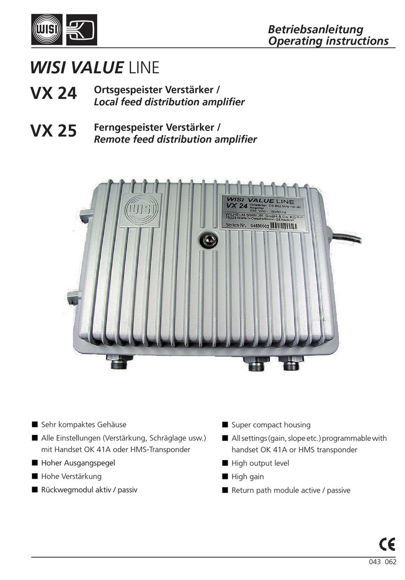
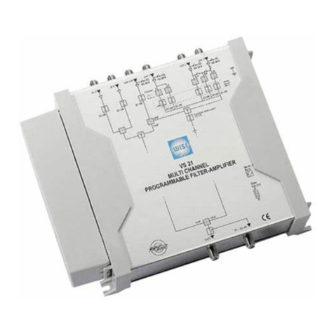
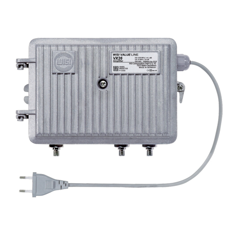
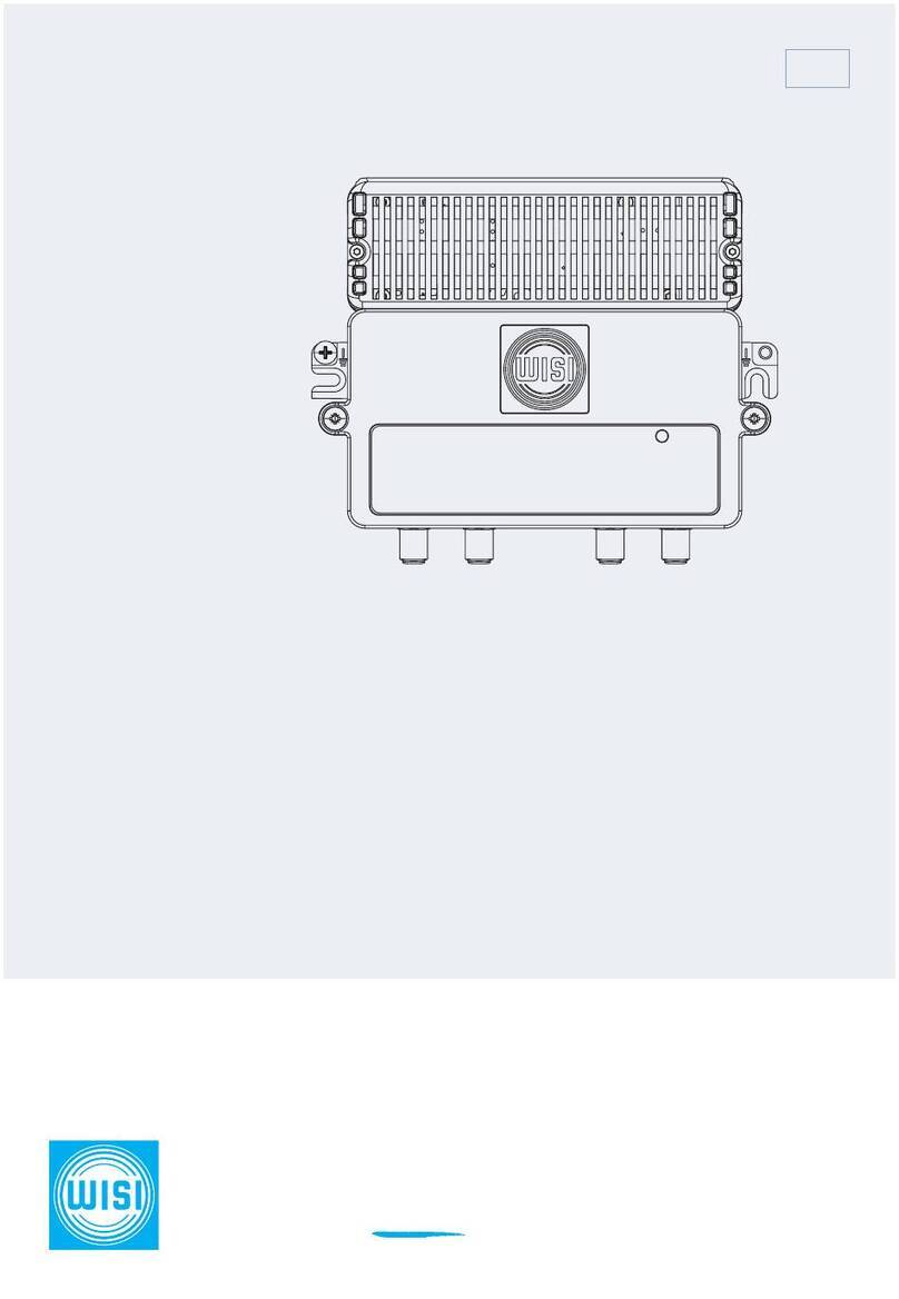
Wisi MIDI Series User manual

Connecting past,
present and future. wisigroup.com
WISI MIDI LINE
Operating instructions
VX 12 K 3626, ...4432
EN

Stay up to date
For more information on your device, visit our support-website:
www.wisiconnect.tv
Aer logging in/registering, you will have access to a variety of interesting infor-
mation and features, such as release notes or installation examples.

Table of Contents
Table of Contents
Important information
1 About this document...........................................4
1.1 Structure of warnings ....................................................4
1.2 Structure of action steps. . . . . . . . . . . . . . . . . . . . . . . . . . . . . . . . . . . . . . . . . . . . . . . . . . 4
1.3 Other symbols ......................................................... 4
2 Safety instructions.............................................5
2.1 General safety instructions................................................5
2.2 Intended use .......................................................... 5
2.3 Improper use .......................................................... 5
2.4 Specialist personnel ....................................................5
2.5 Electrical safety ........................................................5
2.6 ESD protection. . . . . . . . . . . . . . . . . . . . . . . . . . . . . . . . . . . . . . . . . . . . . . . . . . . . . . . . . 6
3 CE-Declaration of Conformity ...................................6
Overview
4 VX 12 K 3626, VX 12 K 4432 ....................................7
4.1 Dimensions ............................................................ 8
4.2 Connectors and adjustment elements ......................................9
4.3 Block diagram ........................................................ 10
4.4 Technical data .........................................................11
Installation
5 Commissioning ..............................................13
5.1 Open the cover ....................................................... 13
5.2 Configure downstream ................................................. 13
5.3 Configure upstream.................................................... 15
5.4 Optional: Insert VT 21 module for ICS settings .............................. 15
5.5 Establish potential equalisation........................................... 16
5.6 Close the cover and connect the device to the mains......................... 16
EN | 3

Important information
1 About this document
These operating instructions are part of the device.
If the warnings, notes and instructions in this document are not followed, WISI does not
assume any warranty or liability for safe operation and function of this device.
If not indicated otherwise, German is the original language. Other languages are translations of
the original language.
1.1 Structure of warnings
Warnings indicate the possible risk of personal injury.
The warnings are always structured as follows:
SIGNAL WORD
Type and source of danger
Consequences of non-compliance
1. Measures to avoid
Four levels are differentiated with the signal word:
DANGER
Immediately serious injuries or death
WARNING
Possible serious injuries or death
CAUTION
Possible minor injuries
ATTENTION
Comprehensive property damage
1.2 Structure of action steps
Instructions for use can begin with an introductory text describing the following objectives. Then
follow the action steps, which always start with a numbering.
Be followed step by step. Safe operation of the device can only be guaranteed if all action steps
are carried out.
1. This is an example of the first step.
2. This is an example of the second step.
1.3 Other symbols
Notes on damage to property and economic use are listed behind this symbol.
4 | EN

Important information
2 Safety instructions
2.1 General safety instructions
The device has been designed and constructed in such a way that hazards have been excluded
as far as possible. Nevertheless, there may be residual risks.
• Before commissioning, familiarize yourself with this manual.
• Check the device carefully for obvious damage. Do not use damaged device! In this case,
please contact your WISI representative.
2.2 Intended use
The device is used exclusively for the installation of HFC networks up to 1218 MHz.
2.3 Improper use
Any other use will result in the loss of warranty or guarantee.
WISI is not liable for any damages resulting from this. The user bears the sole risk.
2.4 Specialist personnel
2.4.1 Assembly and repair
• Installation, repair, alternations, reajustments and upgrades may only be carried out by autho-
rised specialists.
2.4.2 Operation
• Work on the unit may only be carried out by authorised specialists.
2.5 Electrical safety
• Carry out work on the device in accordance with the local safety regulations.
• Observe the safety regulations of the current standards EN 60728-11 and EN 62368-1 or the
national standards.
• Work on the device may only be carried out when the mains is unplugged.
• Replace damaged cables and connectors immediately.
• Connect the unit to a potential equalisation system in accordance with the locally applicable
electrical standards.
• Device does not have a main switch. As soon as the device is plugged in, it is in operation. In
order to turn off the power supply, the mains plug must be removed from the mains socket.
Mains socket must be easily accessible so that the mains plug can be pulled quickly if neces-
sary. Never pull the cable.
• The power supply area of the device as well as all coaxial interfaces with remote power sup-
ply carry dangerous voltages.
• Dangerous live parts must not be touched.
EN | 5
Important information
• When working on the device of any kind, the device must be de-energized.
• The device may only be installed and put into operation in a dry room.
• Do not expose the device to splash water or other liquids.
Do not place liquids on the device.
• Do not mount the device on or near flammable materials.
• Never operate the device without a lid/protective cover.
2.6 ESD protection
The device contains components that are sensitive to electrostatic discharges. In case of im-
proper handling, the device may be damaged, e.g. during unpacking, assembly/disassembly,
storage or shipping.
A harmful discharge can happen unnoticed.
Always take the usual protective measures when handling the device.
3 CE-Declaration of Conformity
The declaration of conformity can be found on our website:
www.wisigroup.com/resource-center
Then navigate to “Downloads” and then to “EU Declarations of Conformity”.
Then please select the document that matches your device.
6 | EN

Overview
Overview
4 VX 12 K 3626, VX 12 K 4432
Cascadable Amplifier, 1 Output
• Compact 1.2 GHz cascadable amplifier with one active output
• Aluminium die-casting housing
• Integrated diplex filters
• Configuration of attentuation, equalization and slope via PADs and jumpers
• Function control LED
• Test points accessible externally
• Very low power consumption
• Interface for optional VT 21 module for ICS setting (Ingress control switch)
• Specified according to Vodafone TS 4002
EN | 7

Overview
4.1 Dimensions
178
61
120
145
133
8 | EN

Overview
4.2 Connectors and adjustment elements
X13 X12
6 dB
0 dB
VX12 K 4432
X11 X10
Grün
Orange
Rot
ICS
M10 - Transponder
0dB
-6dB
OFF
X5
0 / 7 dB
X4
OFF ON
VX12 K 4432
3 6 9,5
12
4
EQ /dB
258-1218
PAD 812 16
14
20
X2
X1
TP - 20dB TP - 20dB OUTPUT DSINPUT DS
1 2 3 4
5
1 Downstream-Input
2 Downstream RF test point
3 Upstream RF test point
4 Downstream-Output
5 Power indicator LED green (in the power supply unit)
M10 Slot for VT 21 module for ICS settings
ICS Status-LED Microreceiver
X1 Downstream input attenuator (DS-IN-ATT) 0...20 dB
X2 Downstream cable simulator (DS-IN Kabel) 0...9 dB
X3 Downstream input equalizer (DS-IN-EQ) 0...20 dB
X4 Downstream amplifier 4432: switchable 36/44 dB; 3626: 36 dB
X5 Interstage Slope (DS-Slope) 0/7 dB
X10 Upstream input attenuator (US-IN-ATT) 0...20 dB
X11 Upstream interstage attenuator (US-Inter-ATT) 0/x dB
X12 Upstream output attenuator (US-OUT-ATT) 0...20 dB
X13 Upstream output equalizer (US-OUT-EQ) 0...20 dB
EN | 9

Overview
4.3 Block diagram
The block diagram of VX 12 E 4432 serves as an example. The other variants differ in
some adjustable values. For detailed information see technical data.
Jumper
DS-Input DS-Output
0...8 dB 0...14 dB 0 / 8 dB
0...20 dB 0 / 6 dB 0...20 dB
LP 5-204 MHz
HP 258-1218 MHz
230 VDC
RX
V DC
TP - 20 dBTP - 20 dB
Jumper
0 / 7 dB
Pad
Pad
Pad Pad
Jumper
1218 MHz 1218 MHz
0/ 6/ OFF
VT21
ICS-Receiver
ICS - LED
0 dB - grün
- 6 dB - orange
OFF - rot
0...20 dB
Pad
0...10 dB
Pad
0/6/45 dB
10 | EN

Overview
4.4 Technical data
The latest technical data can be found on the Internet at www.katalog.wisi.de.
General ...4432 ...3626
Compliance VF TS4002
RF connector F
Impedance 75 Ω
RF test point at the input
(bidirectional)
-20 (±1 dB, 10...204 MHz)
-20 (±2.5 dB, 258...1218 MHz)
RF test point at the output
(directionally coupled)
-20 (±1 dB)
Supply voltage 230 V AC
Power consumption ≤15 W ≤11W
Ambient temperature - 20...+55 °C
Protection class IP20
Surge protection RF ports 4 kV (EN 60728-3)
Power indicator LED green (in
the power supply unit)
green
EMC EN 50083-2
Dimensions (WxHxD) 178x61x133 mm
EN | 11

Overview
Downstream ...4432 ...3626
Frequency range 258...1218 MHz
Gain 44/36 dB switchable 36 dB
Frequency response ± 0.8 dB
In/output return loss ≥16.5 dB (-1.5 dB/Oct.)
Noise figure ≤6 dB ≤5.5 dB
Output level
with 7 dB slope
≤109 dBµV ≤105 dBµV
Operational level
with 7 dB slope
(channel load according to
Vodafone TS 4002)
≤106 dBµV ≤102 dBµV
Input equalizer 0...14 dB (PAD XP)
Attenuator 0...20 dB (PAD XP)
Cable simulator 0...8 dB (Pad XP…)
Interstage Slope 0/7 dB (Jumper)
Upstream ...4432 ...3626
Frequency range 5...204 MHz
Gain 32 dB 26 dB
Frequency response ± 0.8 dB
In/output return loss ≥18 dB (10...204 MHz)
Noise figure ≤5 dB
Output level
(channel load according to
Vodafone TS 4002)
≤108 dBµV, flat
Interstage attenuator 0/6 dB (Jumper) none
Input attenuator 0...20 dB (PAD XP)
Output equalizer 0...10 dB (PAD XP)
Output attenuator 0...20 dB (PAD XP)
Option ICS receiver module 0/6/off,
according to EN 60728-14 -> VT21
12 | EN

Installation
Installation
5 Commissioning
DANGER
Injuries due to electric shock
1. Disconnect the mains plug before opening.
2. Never touch live parts.
The device contains components that are sensitive to electrostatic discharges. Always
take the usual protective measures when handling the device.
5.1 Open the cover
1. Loosen the cover screws and open the cover.
5.2 Configure downstream
5.2.1 Input attenuator (X1)
The attenuation can be adjusted via a PAD in 1 dB steps.
1. Set the damping (PAD) according to the following table.
5.2.2 Cable simulator (X2)
The cable simulator can be adjusted via a PAD in 1 dB steps.
1. Set the cable simulator (PAD) according to the level plan.
PAD Attenuator
(dB)
Cable simulator
258...1218 MHz
(dB)
2 1.5
4 3
6 4.5
8 6
10 8
EN | 13

Installation
5.2.3 Input equalizer (X3)
The equalization can be adjusted via a PAD in 1 dB steps.
1. Set equalizer (PAD) according to the following table.
PAD Attenuator
(dB)
Equalizer
258...1218 MHz
(dB)
2 1.5
4 3
6 4.5
8 6
10 8
12 9.5
14 11
16 12
18 13
20 14
5.2.4 Amplifier (X4)
Valid only for ...4432:
The amplifier in downstream can be set via a jumper.
44 dB
36 dB
5.2.5 Interstage Slope (X5)
The Interstage slope can be set via a jumper.
1. Set Interstage slope (Jumper) according to the level plan.
Slope enabled
Slope disabled
14 | EN

Installation
5.3 Configure upstream
5.3.1 Input attenuator (X10)
The attenuation can be adjusted via a PAD in 1 dB steps.
1. Set the attenuation (PAD) according to the level plan.
5.3.2 Interstage attenuator (X11)
Valid only for ...4432:
The interstage attenuator can be set via a jumper.
1. Set the interstage attenuator (jumper) according to the level plan
0 dB
6 dB
5.3.3 Output attenuator (X12)
The attenuation can be adjusted via a PAD in 1 dB steps.
1. Set the attenuation (PAD) according to the level plan.
5.3.4 Output equalizer (X13)
The equalization can be adjusted via a PAD in 1 dB steps.
1. Set equalization (PAD) according to the level plan.
5.4 Optional: Insert VT 21 module for ICS settings
The VT 21 allows remote setting of the ICS function and therefore attenuations of 0 dB, 6 dB or
45 dB. Without a plugged-in module, the attenuation is 0 dB. The configuration of the module is
displayed via the LED:
LED Description
Off No microreceiver plugged in
green Microreceiver plugged in, ICS = 0 dB
orange Microreceiver plugged in, ICS = 6 dB
red Microreceiver plugged in, ICS = 45 dB
1. Insert the VT 21 module into the M10 slot.
EN | 15

Installation
5.5 Establish potential equalisation
1. Connect the unit to a potential equalisation system in accordance with the locally applicable
electrical standards. For this purpose, one of the two places marked with must be used.
5.6 Close the cover and connect the device to the mains
1. Close the cover and tighten the cover screws.
Note the orientation of the cover. If the cover is mounted the wrong way around, the
Status-LED Receiver is no longer visible when the cover is closed.
2. Insert the power plug in the AC wall outlet.
If the unit is supplied with power, the power indicator LED will light up green.
16 | EN


Other manuals for MIDI Series
2
This manual suits for next models
2
Table of contents
Other Wisi Amplifier manuals

Wisi
Wisi VX 12 V 2220 User manual

Wisi
Wisi VX 52 B Series User manual

Wisi
Wisi VX 24 User manual

Wisi
Wisi Chameleon User manual

Wisi
Wisi VX 56 B Series User manual

Wisi
Wisi VS 21 User manual

Wisi
Wisi VX 52 A User manual

Wisi
Wisi VX 52 User manual

Wisi
Wisi VX 56 B Series User manual

Wisi
Wisi MIDI Series User manual