Seibersdorf Laboratories POD 16 User manual
MANUAL
POD - Precision Omnidirectional Dipole
Antenna POD 16
Antenna POD 618
Antenna Stand for
Site VSWR Measurements


EMC & OPTICS
MANUAL
POD – Precision Omnidirectional Dipole
Antenna POD 16
Antenna POD 618
Site VSWR Positioner SPM1 (manual)
Site VSWR Positioner SPA1 (automatic)
14.02.2011
Version 3.1

| POD MANUAL SEIBERSDORF LABORATORIES
2
Notice
Seibersdorf Labor GmbH reserves the right to make changes to any product described herein in order to
improve function, design or for any other reason. Nothing contained herein shall constitute Seibersdorf Labor
GmbH assuming any liability whatsoever arising out of the application or use of any product or circuit
described herein. All graphs show typical data and not the measurement values of the individual product
delivered with this manual. Seibersdorf Labor GmbH does not convey any license under its patent rights or
the rights of others.
© Copyright 2011 by Seibersdorf Labor GmbH. All Rights Reserved.
No part of this document may be copied by any means without written permission from
Seibersdorf Labor GmbH
Contact
Seibersdorf Labor GmbH
EMC & Optics – RF-Engineering
T +43(0) 50550-2882 | F +43(0) 50550-2881
www.seibersdorf-laboratories.at/rf
VAT no.: ATU64767504, Company no. 319187v, DVR no. 4000728
Bank account: Erste Bank, sort code 20111, account no. 291-140-380-00

SEIBERSDORF LABORATORIES POD MANUAL | 3
Table of Contents
1. INTRODUCTION................................................................................................................................ 5
2. DESCRIPTION OF THE POD ANTENNA & POSITIONER............................................................... 6
2.1. POD Antenna ..................................................................................................................................... 6
2.2. Site VSWR Positioner ........................................................................................................................ 8
3. CONTENT OF SETS.......................................................................................................................... 9
3.1. POD Antenna Set............................................................................................................................... 9
3.2. Components Specific to SPA1 ......................................................................................................... 10
3.3. Components Specific to SPM1 ........................................................................................................ 10
3.4. Components for SPM1 and SPA1.................................................................................................... 11
3.5. Site VSWR Set with SPM1............................................................................................................... 11
3.6. Site VSWR Set with SPA1 ............................................................................................................... 12
4. TECHNICAL SPECIFICATIONS...................................................................................................... 13
4.1. Technical Specifications of POD Antennas ..................................................................................... 13
4.2. Radiation Pattern.............................................................................................................................. 16
4.2.1. Radiation Pattern POD 16................................................................................................................ 17
4.2.2. Radiation Pattern POD 618.............................................................................................................. 19
4.3. Technical Specifications of Site VSWR Positioner .......................................................................... 24
5. INSTALLATION................................................................................................................................ 26
5.1. Assembly of SPM1 - Manual Site VSWR Positioner........................................................................ 26
5.2. Assembly of SPA1 – Automatic Site VSWR Positioner ................................................................... 29
5.3. Polarization Change......................................................................................................................... 33
5.4. Change of Height ............................................................................................................................. 33
5.5. SPA1 Maintainance.......................................................................................................................... 34
5.6. Packing SPA1 in Flight Case ........................................................................................................... 34
6. SOFTWARE ..................................................................................................................................... 35
6.1. SPA Mover ....................................................................................................................................... 35
7. OPERATION .................................................................................................................................... 37
7.1. Site VSWR-Measurement ................................................................................................................ 37
7.2. Field Strength Measurements .......................................................................................................... 39
7.3. Add3D Field Strength Measurements Using sPOD Antennas......................................................... 39
8. LITERATURE AND INFORMATION................................................................................................ 42
9. FIGURES ......................................................................................................................................... 43
10. TABLES............................................................................................................................................ 44
ANNEX I. WARRANTY .............................................................................................................................. 45
ANNEX II. SAMPLE CERTIFICATE OF ANTENNA CALIBRATION .......................................................... 46

| POD MANUAL SEIBERSDORF LABORATORIES
4

SEIBERSDORF LABORATORIES POD MANUAL | 5
1. INTRODUCTION
The Precision Omnidirectional Dipole (POD) was developed by Seibersdorf Laboratories (former ARC) due
to industry demand for an omnidirectional broadband antenna. It’s covering the frequency range 1-18 GHz
with two antennas (1-6 GHz, 6-18 GHz).
Design goal was a superior radiation pattern performance exceeding the standard requirements for Site
VSWR measurements [1] by far. Thus has leaded to a construction which is patented by Seibersdorf
Laboratories.
The POD Antenna can be used for any kind of RF test where an omnidirectional broadband characteristic is
required.
This manual describes in detail the application of the POD Antenna for Site VSWR measurement using the
Site VSWR Positioner SPA1 and SPM1 (former POD Antenna Stand).
For isotropic field strength measurements with the Field Nose system shortened versions of the antennas
are available (sPOD series).
Technical specification of the antennas and radiation patterns are presented.
| POD MANUAL SEIBERSDORF LABORATORIES
6
2. DESCRIPTION OF THE POD ANTENNA & POSITIONER
2.1. POD Antenna
The POD Antennas cover the frequency range 1 GHz up to 18 GHz with two models:
POD 16 for the range 1 GHz to 6 GHz and
POD 618 for the range 6 GHz to 18 GHz.
Covering the whole frequency range with one antenna would lead to dramatic performance degradation at
the band ends. So the frequency range is split and there are two antennas with optimum performance. As
split frequency 6 GHz was chosen because the standard CISPR 22 [2] requires measurements up to 6 GHz
only. So the validation is required up to 6 GHz only and can be performed with one antenna. In Figure 1 the
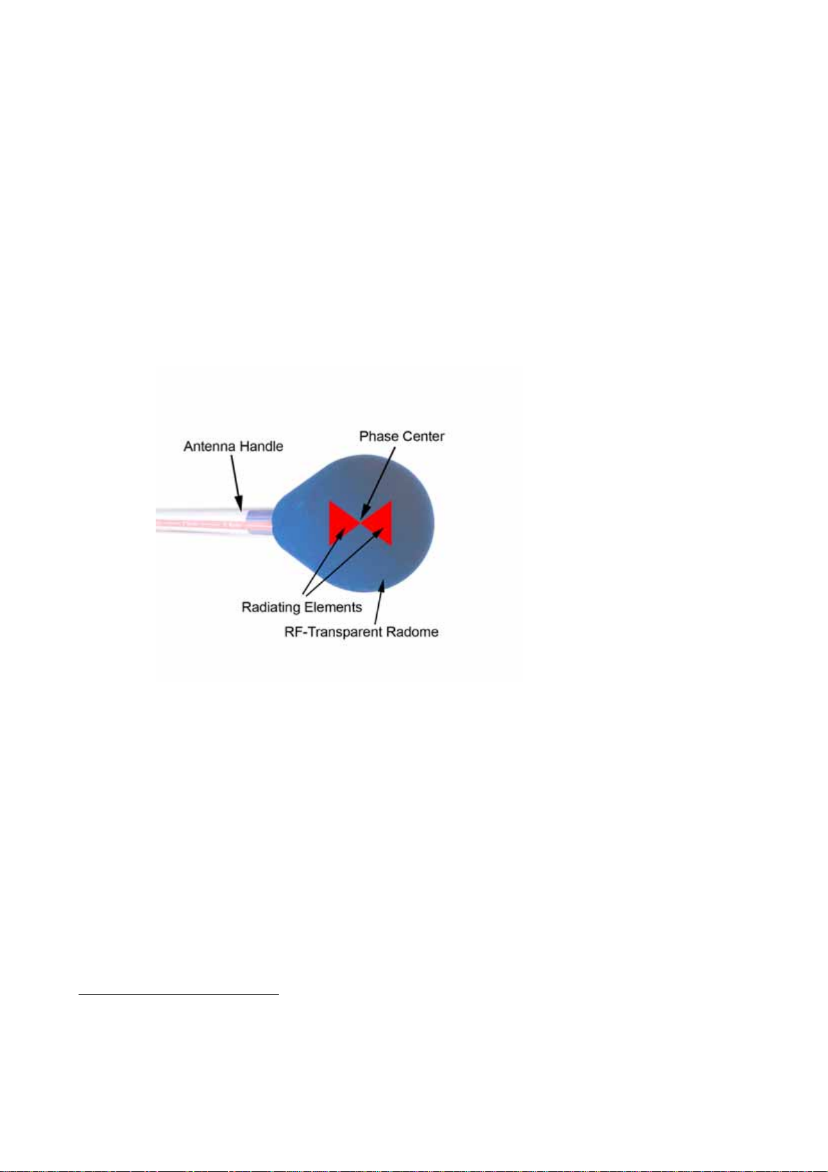
schematic of the POD construction is shown.
Figure 1: Schematic drawing of POD Antenna construction
In Figure 2 a comparison of the radiation pattern of the ideal dipole and two practical realisations is given. In
the “classical” biconical design the pattern is distorted (compared to the ideal dipole) in the region around
the antenna feed cable. The biconical pattern shown in Figure 2 does not fulfil the requirements given by
CISPR 1.
1CISPR 16-1-4 (8.2.2.1)
E-Plane: The E-plane pattern shall not enter the forbidden area (-3 dB for ± 15°, symmetrical to the main lobe directions on both sides
of the pattern).
H-Plane: “Note: Although a lower bound on the H-plane pattern is not specified outside of ±135°, it is desirable for the H-plane pattern
not to show a null at ±180º, but to be omni-directional as best as possible.”

SEIBERSDORF LABORATORIES POD MANUAL | 7
The patented POD Antenna design avoids coupling with the feed cable and its pattern is close to the ideal
dipole. In Figure 3 an example of real measurement data is given. For the whole set of directional pattern
see Chapter 4.2. The radiating elements are covered with a RF-transparent radome for protection during
handling and transportation.
Figure 2: Radiation pattern (yellow) for different dipole antenna designs (black) in E- and H-Plane.
The pattern of the POD Antenna is very similar to the ideal dipole.
Figure 3: Normalized E- and H-plane radiation pattern results for a POD 16 at 4 GHz and forbidden
areas (gray) defined by the standard for Site VSWR measurement
Ideal Dipole Biconical Antenna POD Antenna
E-Plane
H-Plane
| POD MANUAL SEIBERSDORF LABORATORIES
8
2.2. Site VSWR Positioner
When omnidirectional antennas have to be mounted special care has to be taken not to influence the
antenna behaviour. Biconical antennas for the frequency range 30 MHz to 200 MHz are mounted on plastic
masts (and not on metal) for height scanning. This is sufficient for this frequency range but not suitable for
frequencies above 1 GHz. Metallic and plastic material must not be present within the vicinity of the radiation
elements2.
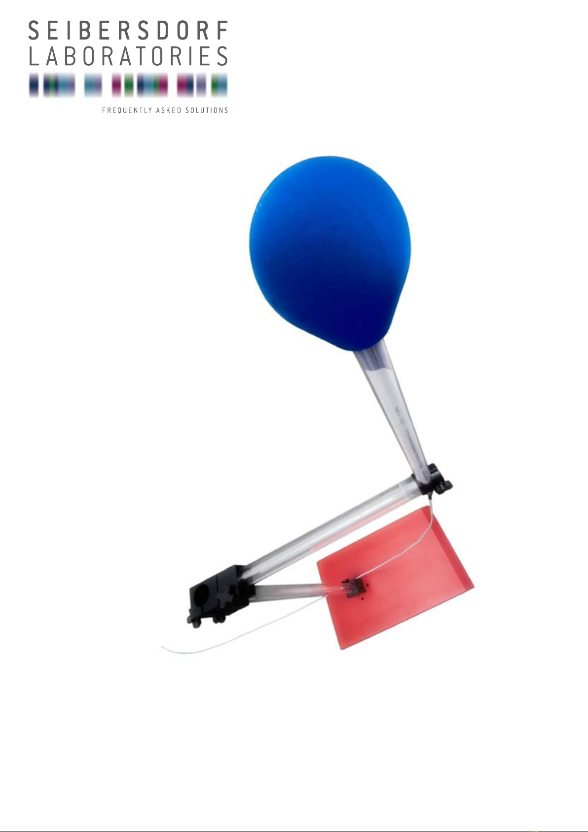
The Site VSWR Positioner SPM1 (former POD Antenna Stand), see Figure 4, left, is especially designed to
optimize this new Site-VSWR measurement procedure in several ways:
Minimize influence of antenna mast on result
Well defined cable routing
Repeatable results
Easy positioning and polarization change
The automatic Site VSWR Positioner SPA1, see Figure 4, right, additionally increases the speed of
validation. The 6 positions per measurement location are set up automatically via the CalStan 10.0 Site
VSWR plug-in thus reducing the manual setup modifications by up to 84%
Figure 4: Site VSWR Positioner
Left: SPM1: Manual Positioner with POD Antenna mounted in vertical polarization
Right: SPA1: Automatic Positioner
2CISPR 16-1-4 (8.2.2.1): “Note: Guidance provided by the antenna manufacturer on the routing of the feed cabling and antenna mast
should be followed, if available, to minimize the possible influence on H-plane pattern outside of ±135°"
SEIBERSDORF LABORATORIES POD MANUAL | 9
3. CONTENT OF SETS
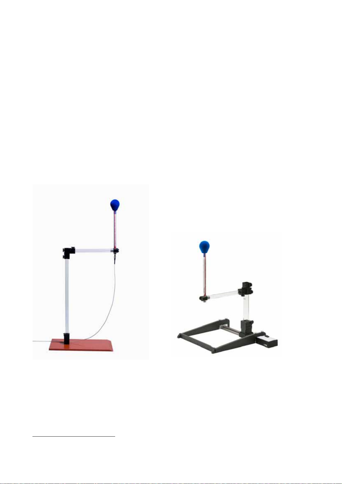
Seibersdorf Laboratories is offering two sets to the customers. The first one is the POD Antenna Set and the
second one is the Site-VSWR Set. Optionally also single components of these sets could be ordered
according to the list of options of our POD price list.
Figure 5: Available sets for Site-VSWR evaluation
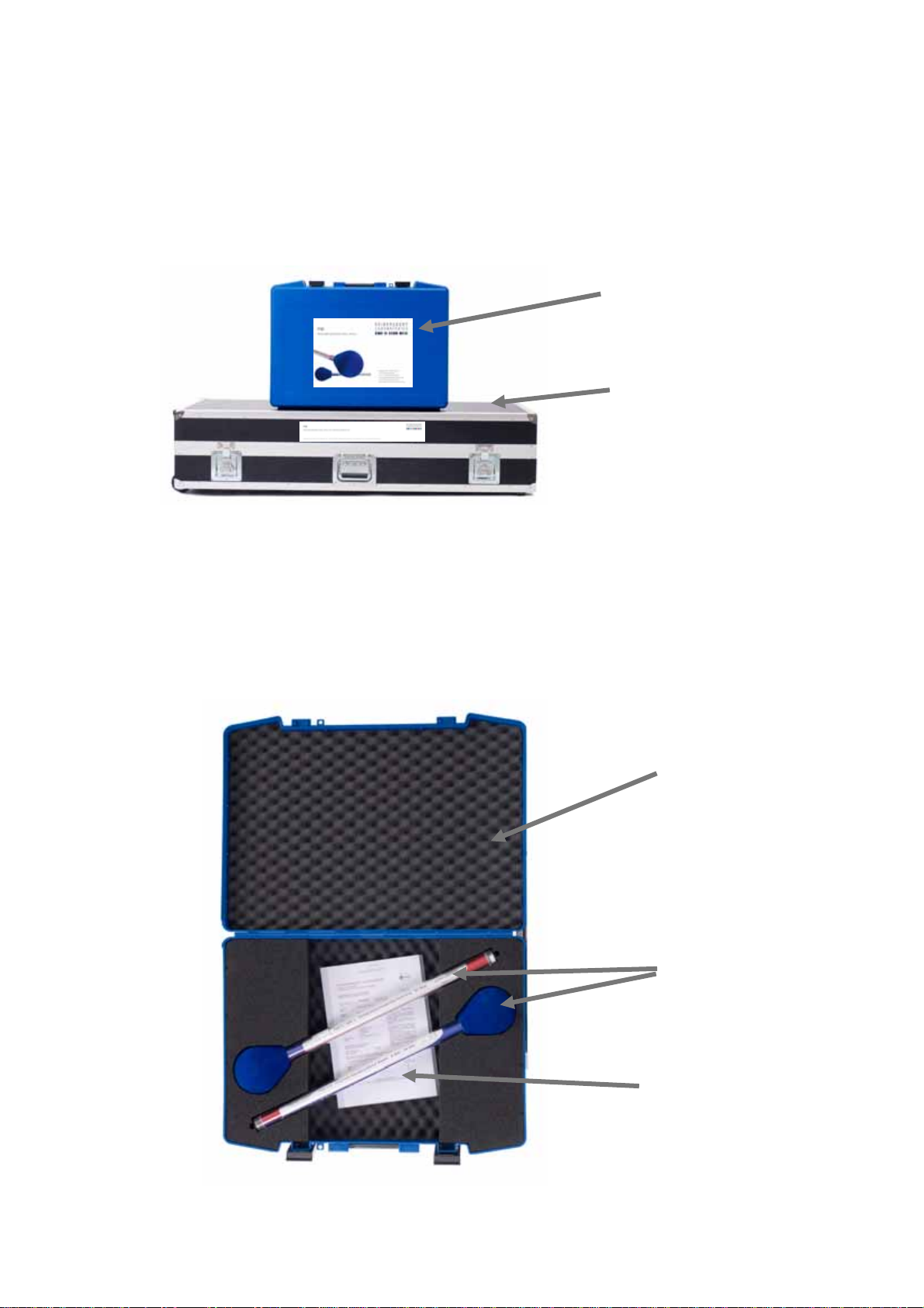
3.1. POD Antenna Set
The components of this set are shown in Figure 6. It consists of the antennas POD 16 and POD 618, ÖKD
antenna calibration certificates for each antenna and this manual, packed in a blue transportation case.
Figure 6: POD Antenna Set
Transportation Case
POD 16 and POD 618
Manual and Certificates
POD Antenna Set
Site VSWR Set
(including POD Antenna Set)
| POD MANUAL SEIBERSDORF LABORATORIES
10
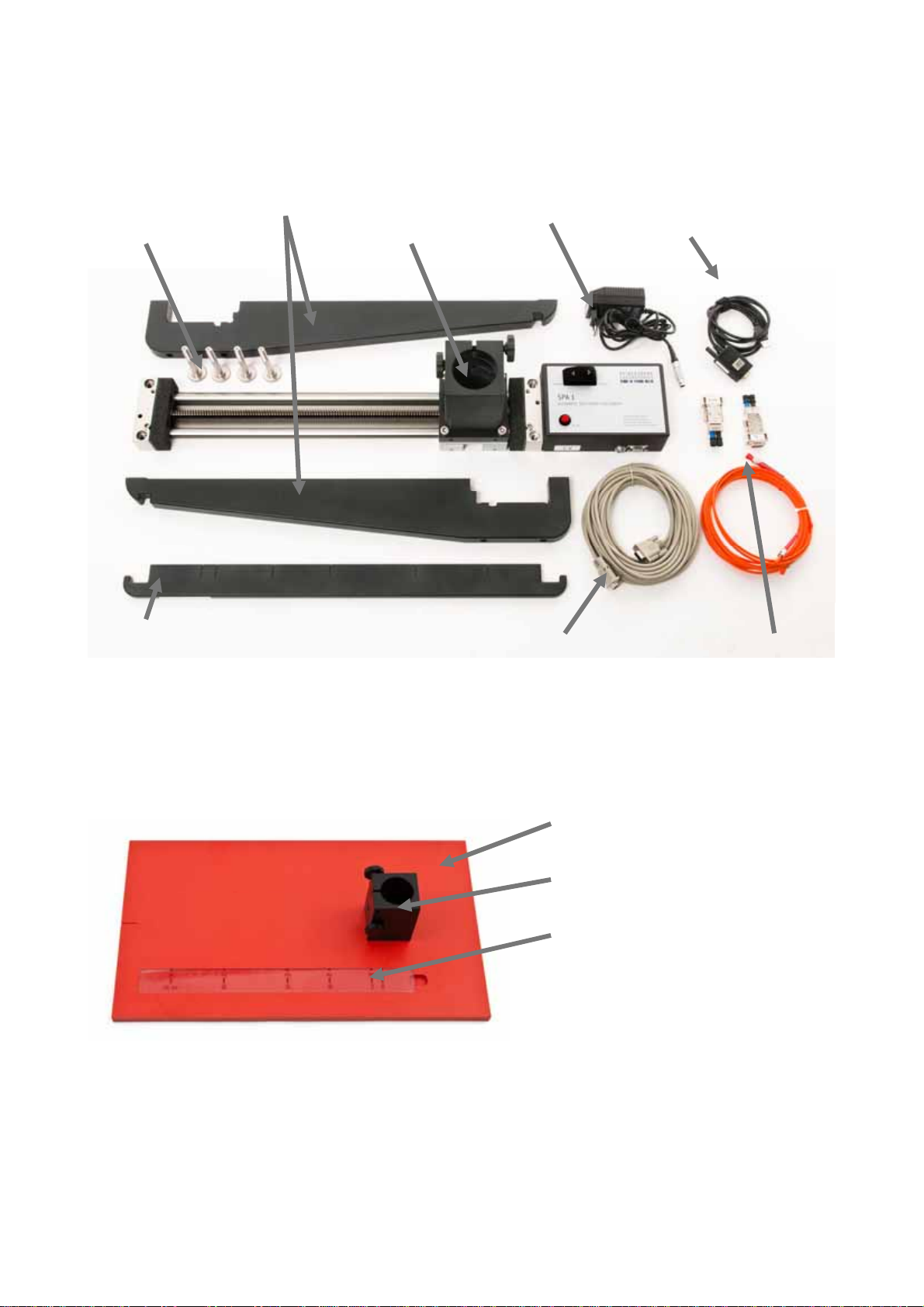
3.2. Components Specific to SPA1
Figure 7: Components of SPA1 automatic Site VSWR Positioner
3.3. Components Specific to SPM1
Figure 8: Components of SPM1 manual Site VSWR Positioner
Positioner with
Tube Base
Ruler
Brackets
4 Bracket Mounting
Screws
Power Supply USB - RS232
Converter
RS232 Cable LWL - RS232
Converter (optional)
Base Plate
Tube Base
Ruler

SEIBERSDORF LABORATORIES POD MANUAL | 11
3.4. Components for SPM1 and SPA1
Figure 9: Components of Site VSWR Positioners
3.5. Site VSWR Set with SPM1
Figure 10: Site VSWR Set with SPM1 manual Site VSWR Positioner
34
34 x M10 x 50 hexagon socket for mounting the Tube Base
1 x Allen key, 6 mm
4different length and amount, depending on the test volume height
Flight Case
Manual and Certificates Base Plate
Mounting material3
POD Antenna Set
Tube Connector
HV-Connector
Tube Base
Tubes4
POD Holder
Ruler
Tube B
Tube A
Tube Connector
HV-Connector
POD Holder

| POD MANUAL SEIBERSDORF LABORATORIES
12
3.6. Site VSWR Set with SPA1
Figure 11: Site VSWR Set with SPM1 manual Site VSWR Positioner
Flight Case
RS232 Cable and optional
LWL cable with converter
Positioner with
Tube Base
POD Antenna Set
Tube Connector
HV-Connector
Tubes
POD Holder
Brackets and
Ruler below
Power Supply

SEIBERSDORF LABORATORIES POD MANUAL | 13
4. TECHNICAL SPECIFICATIONS
4.1. Technical Specifications of POD Antennas
Specification POD 16 POD 618
Frequency range 1 - 6 GHz 6 - 18 GHz
H-Plane anisotropy ± 0.5 dB ± 0.8 dB
Typical antenna factor 37 - 49 dB/m 49 - 59 dB/m
Typical VSWR < 2.0
Phase center center of radome
Connector type SMA female
Total antenna length 610 mm
Radome tip to phase center 50 mm
Diameter handle 30 mm
Antenna weight ~ 290 g ~ 255 g
Max. input RF-power 30 dBm
Field strength damage level 200 V/m
Temperature operating range 5°C - 45°C
Humidity (non condensing) < 98%
Dimensions of Antenna Set 64 x 47 x 15 cm
Weight of Antenna Set ~ 5 kg
Table 1: Technical specifications of POD Antennas
| POD MANUAL SEIBERSDORF LABORATORIES
14
a)
b)
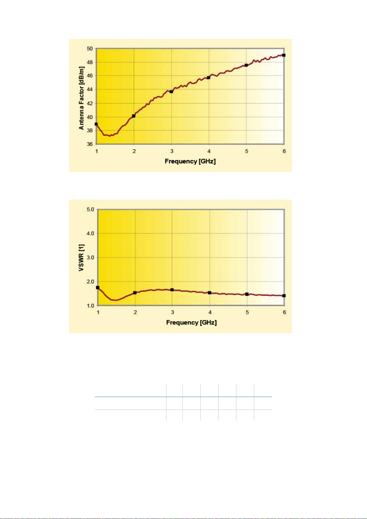
Figure 12: Typical Calibration data for POD 16
a) Antenna factor measured in 0° direction
b) VSWR
Frequency [GHz] 1 2 3 4 5 6
Antenna Factor [dB/m] 38.9 40.1 43.6 45.7 47.5 49.0
VSWR [1] 1.7 1.5 1.6 1.5 1.5 1.4
Table 2: Typical antenna factor and VSWR for POD 16
SEIBERSDORF LABORATORIES POD MANUAL | 15
a)
b)
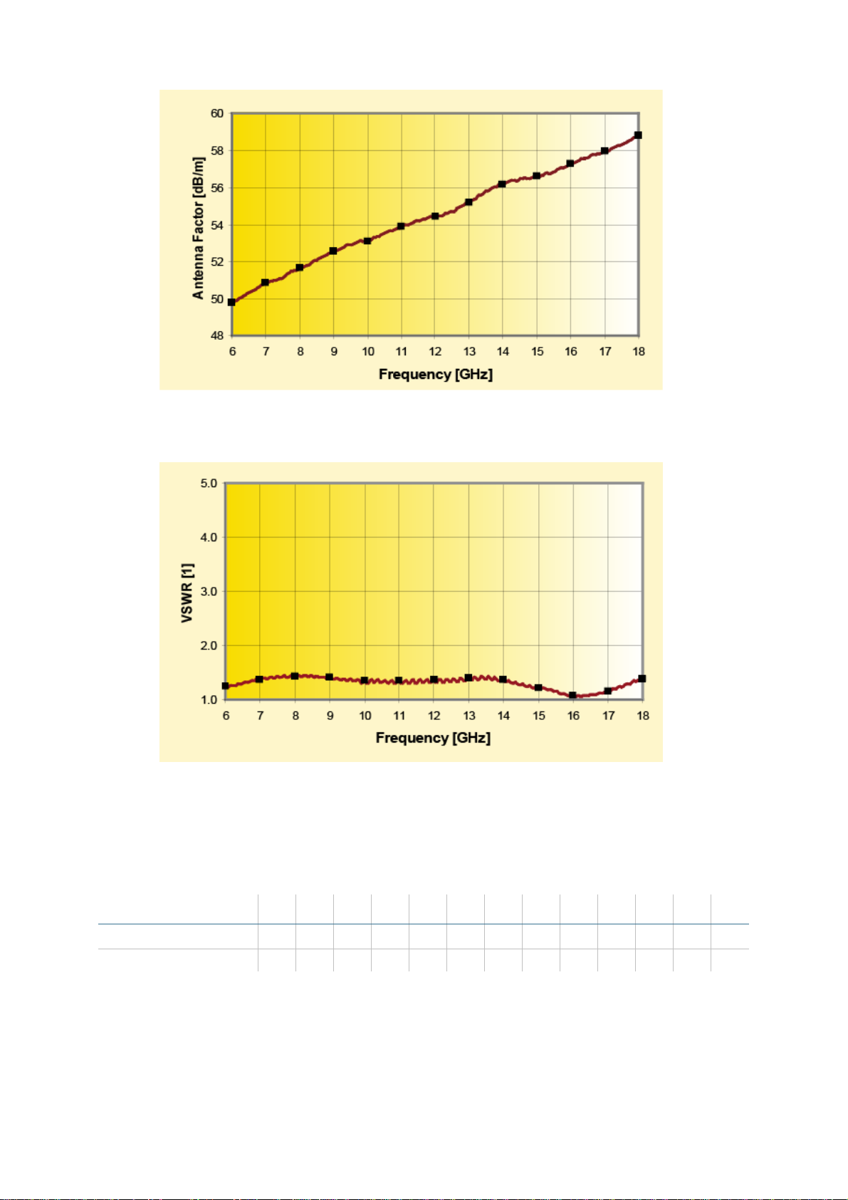
Figure 13: Typical Calibration data for POD 618
a) Antenna factor measured in 0° direction
b) VSWR
Frequency [GHz] 6 7 8 9 10 11 12 13 14 15 16 17 18
Antenna Factor [dB/m] 49.8 50.8 51.7 52.6 53.1 53.9 54.4 55.2 56.2 56.6 57.3 57.9 58.8
VSWR [1] 1.2 1.4 1.4 1.4 1.3 1.4 1.4 1.4 1.4 1.2 1.1 1.2 1.4
Table 3: Typical antenna factor and VSWR for POD 618
| POD MANUAL SEIBERSDORF LABORATORIES
16
4.2. Radiation Pattern
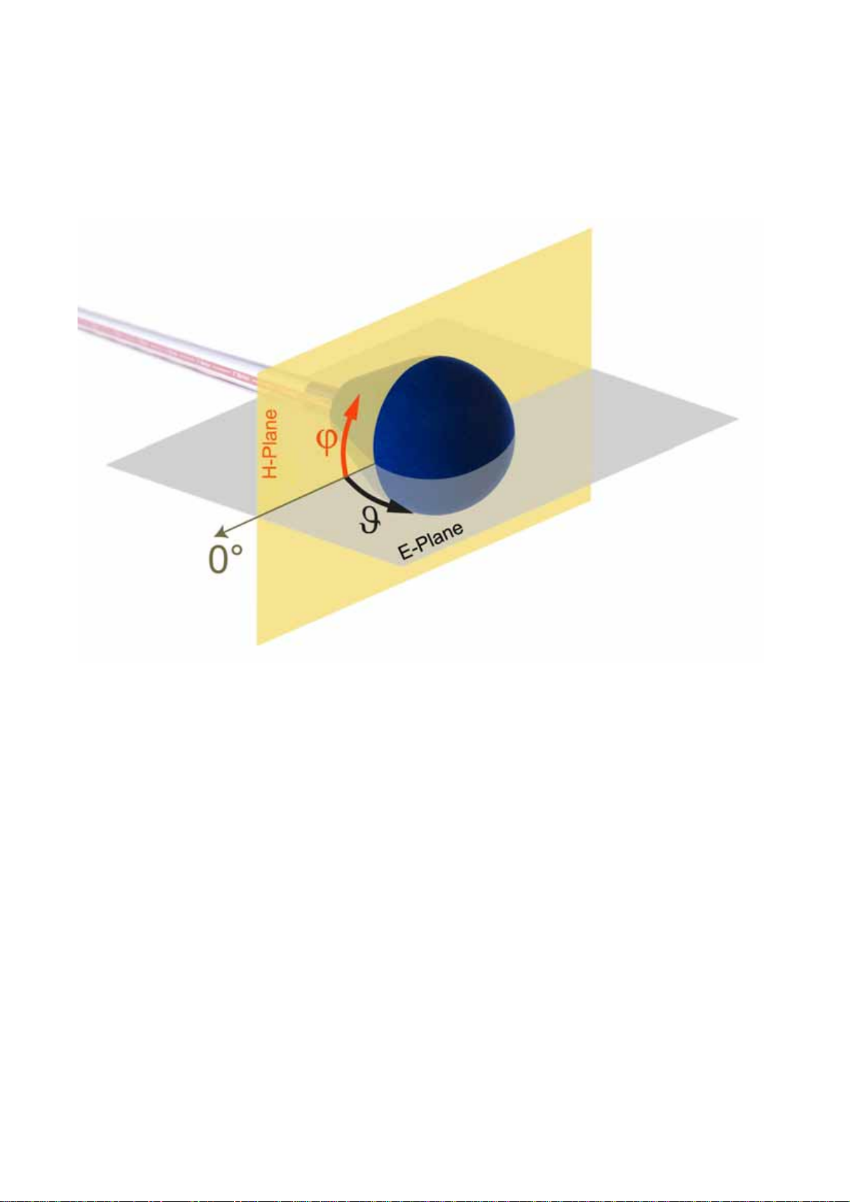
The following Figure 14 shows a POD Antenna and visualizes the E- and the H-plane. Also the angles
and φused for the radiation pattern diagrams are defined in this Figure.
Figure 14: Definition of E- and H-planes for the radiation pattern diagrams
A normalization of the radiation pattern is required by the standard. This is necessary to apply the criteria
and is performed for each pattern.
For E-plane and H-plane this is done in a different manner:
E-plane:
The pattern is normalized to the largest value (0 dB)
H-plane:
The mean value of the pattern is calculated in an angular range from -135° to +135°. The full pattern
(angular range ±180 °) is normalized to this average (0 dB).

SEIBERSDORF LABORATORIES POD MANUAL | 17
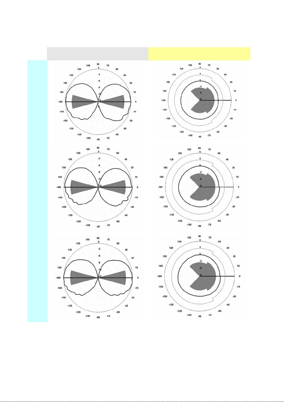
E-Plane H-Plane
1 GHz
2 GHz
3 GHz
4.2.1. Radiation Pattern POD 16
| POD MANUAL SEIBERSDORF LABORATORIES
18
Radiation Pattern POD 16 continued:
Figure 15: Radiation Pattern POD 16
E-Plane H-Plane
4 GHz
5 GHz
6 GHz
This manual suits for next models
1
Table of contents
Popular Antenna manuals by other brands


One Forall
One Forall 17411 Quick installation guide

Williams Sound
Williams Sound ANT 033 Manual and user guide

VuQube
VuQube VQ2000 operating instructions

Stim Wave Technologies
Stim Wave Technologies PDBT-915-2K user manual

Maxview
Maxview COMBO/51 Installation & user's instructions

Antop
Antop AT-105 manual


