
Version No. 1-8 - 12.09.2023 Doc. No. 9987120082USL 10 / 25
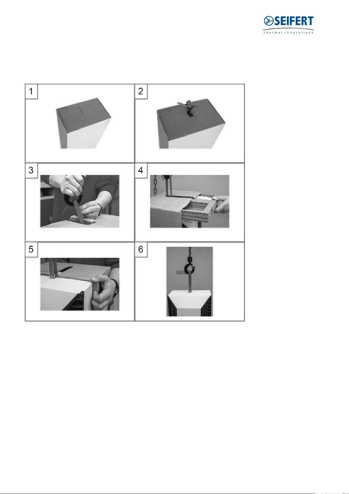
Mounting:
The power supply rating on unit rating plate must comply with mains rating.
Always disconnect the power supply before opening the unit.
The heat load to be dissipated from enclosure should not exceed specific cooling output of the unit at any
condition. At cooling unit selection always cater for a safety margin of at least 15% extra cooling output in the
worst conditions. Air inlets and outlets must be completely free from obstruction.
Ensure that flows of air leaving and entering the cooling unit, internal and external, are not obstructed. Cooling
unit enclosure air suction hole must be installed in the highest possible point. When installing the unit on a door
ensure it can take the weight.
Before drilling the enclosure ensure the fixing elements and couplings will not interfere with the equipment
inside the enclosure itself. Disconnect power before starting any work inside the enclosure. Following this 1:1
Scale Drilling Template drill the holes and make the required cuts on the enclosure. This template may have
been affected by storage conditions, please check this template by verifying values of the largest dimensions
before drilling. Fit the sealing strip on the cooling unit on the side connected to the enclosure and follow the
installation diagram.
This AC unit can only be mounted to a suitably Type rated enclosure to maintain it's Type rating. The Type and
IP rating of the enclosure should be the same or higher than that of the unit.
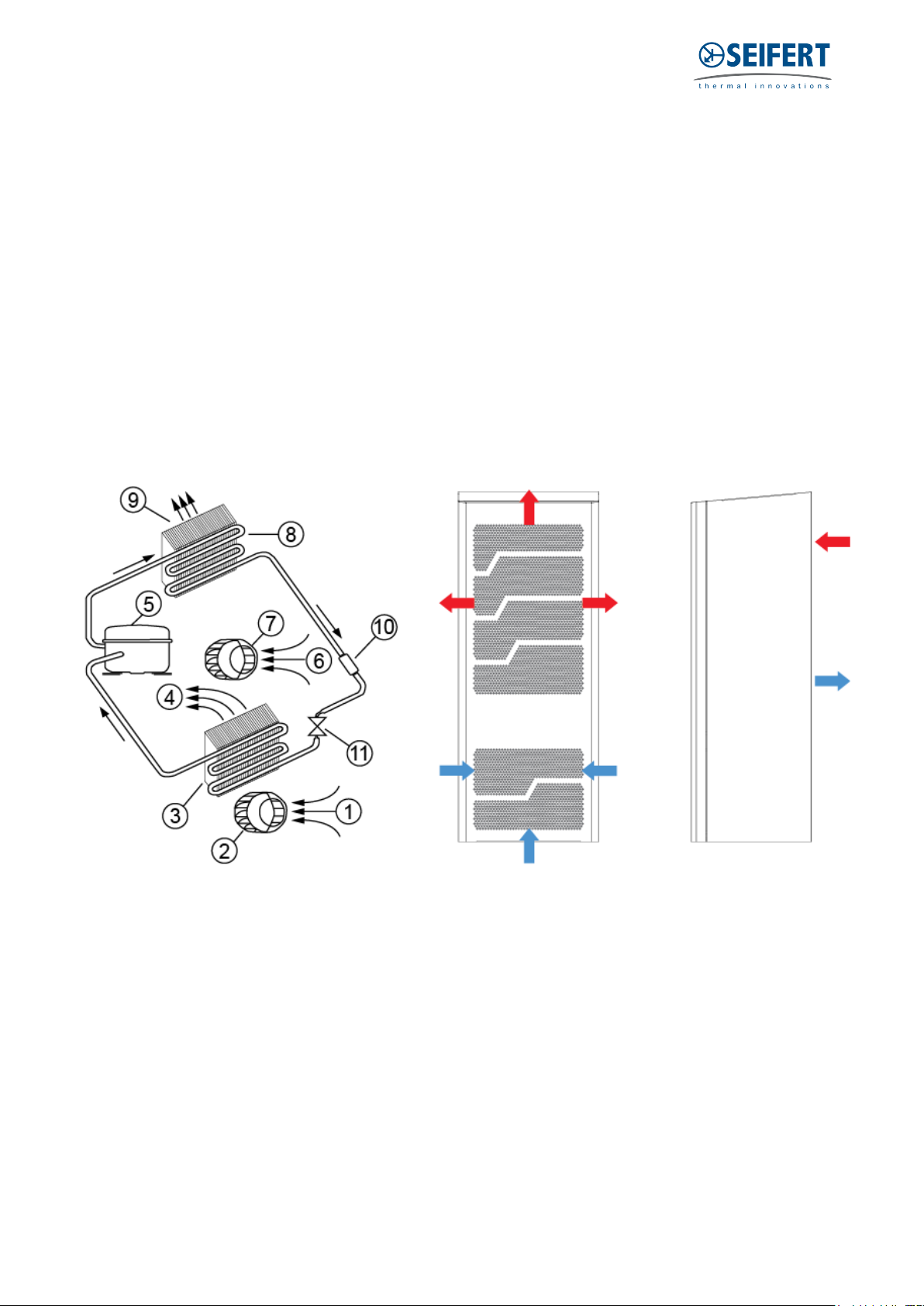
9. Condensate management
High humidity and low temperatures inside the enclosure can lead to condensation on the evaporator.
Condensate that flows back into the enclosure can damage sensitive control electronics. The integrated
condensate evaporation of the cooling unit releases the condensate to the environment. If condensate
formation is too great, additional condensate can drip into an overflow trough, which then drains off on the
ambientt side.In order to prevent the formation of excessive condensate, you should nevertheless:
- check the seals at regular intervals
- consider installing a door contact switch (order no. 3100001). This can prevent condensation forming
when enclosure door is left open.


 user manual")


