SEIKAKU TECHNICAL GROUP AUDIO MATRIX RPM200 User manual

RPM200
Paging Station
USER'S MANUAL
AUDIO MATRIX

INDEX
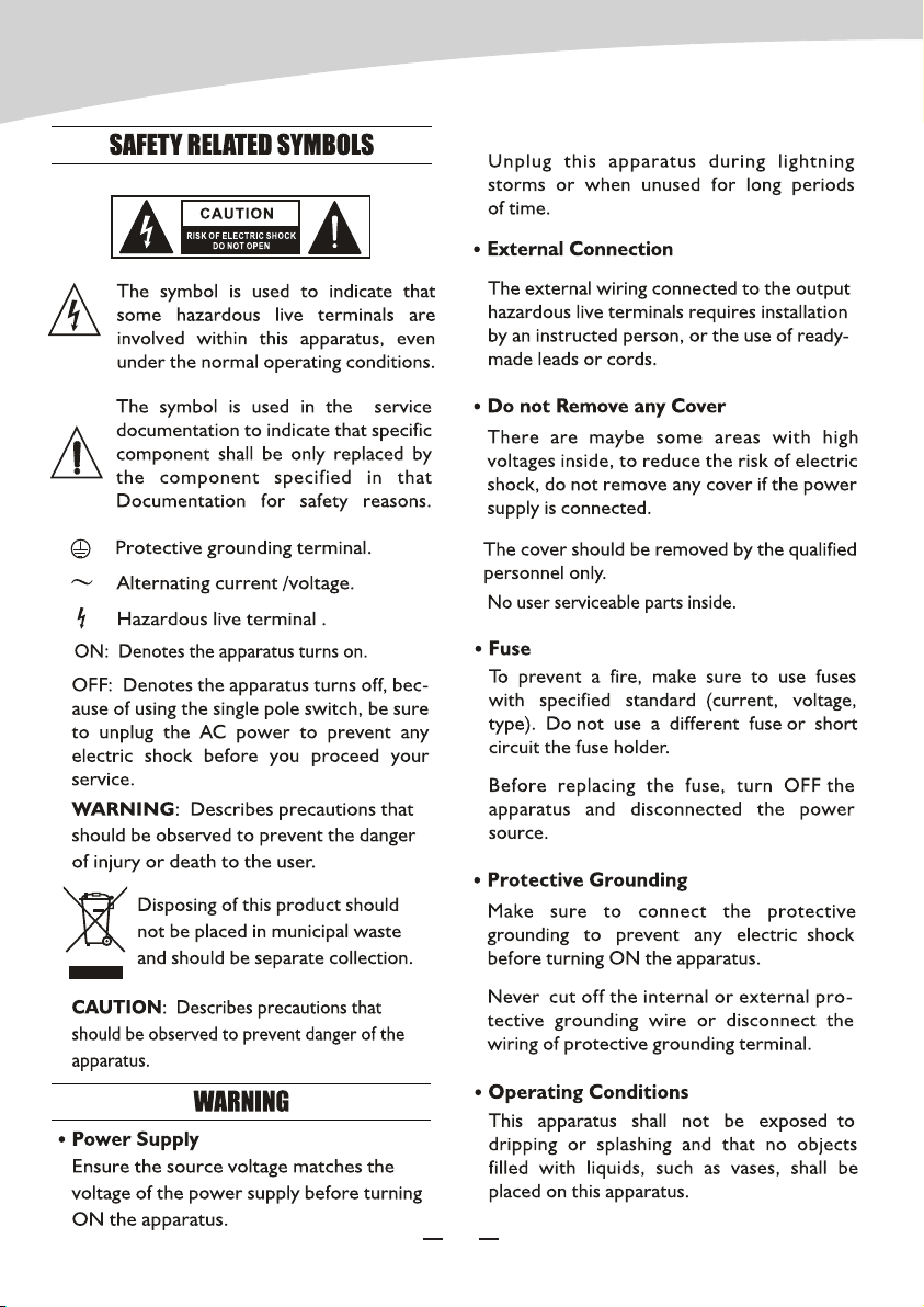
01 SAFETY RELATED SYMBOLS
02 WARNING
03 IMPORTANT SAFETY INSTRUCTIONS
04 FOREWORD
05 AUDIO MATRIX
06 SYSTEM PREVIEW
07 BASIC OPERATION
08 PHYSICAL INSTALLATION
09 OPERATION
10 SOFTWARE CONTROL
11 FIRMWARE UPDATE
12 FAQ
13 SPECIFICATIONS
1
1
2
3
3
4
7
8
8
9
13
13
14
AUDIO MATRIX
1
AUDIO MATRIX

2
AUDIO MATRIX
Thanks to purchase the product of our company, please read this manual carefully before
any operation.
Note: This guide contains all the information needed for the product. There might be some
differences between the item and its description; please refer to the real product for the
features.
Audio Matrix is a system which contains multiple signal inputs and outputs; each input can
be assigned to any output like matrix in mathematics. Parameters controls are available for
all the inputs and outputs, and are easily changeable; all the configurations can be backed
up and restored, easy to copy and to extend. Audio Matrix gives the ability to build
complex audio setup in one device providing an instinctive operating interface for both
professional and beginner.
FOREWORD
AUDIO MATRIX
3
AUDIO MATRIX

SYSTEM PREVIEW
4
Audio Matrix is a system which combines the hardware with software. The core device is
Matrix A8 or Matrix D8. The major features are listed below:
1.12 INPUTS and 12 OUTPUTS
2. In case of extension links, the maximum goes up to 192 inputs and outputs.
3.Broadcast different zones simply by paging unit control.
4.A remote control unit can assign the volume in different zones separately.
5.Control signals are transferred individually with dedicated wires separated from the audio
stream, avoiding conflicts and improving the flexibility and the reliability.
6. The transmission for audio stream is based on AES/EBU protocol, while the control
signal used a RS-485 format.
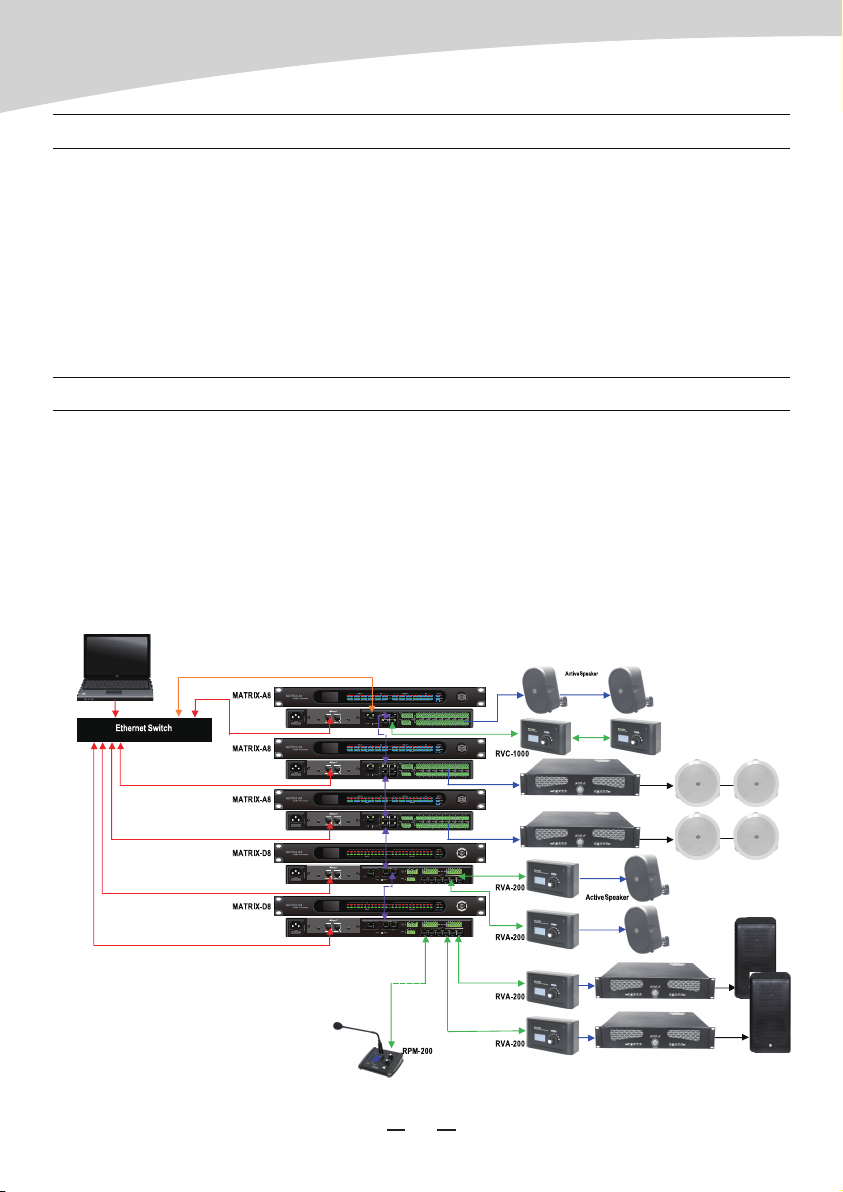
There are six members in the MATRIX SYSTEM family:
MATRIX A8 --- Server host;
MATRIX D8 --- Server host (Compared to A8, 8 analog I/O for the A8, 8 digital I/O for D8);
RVC1000 --- Remote volume control with a link port;
RVA200 --- Remote volume control with additional outputs;
RIO200 --- Remote analog inputs and outputs;
RPM200 --- Remote paging station.
By using a combination of the above six devices, most of the broadcasting or routing
requirements can be fulfilled.
This system fits perfectly for schools, middle and small companies, supermarkets, bars and
restaurants, health clubs, small libraries … The friendly and quick implementation of
primary and advance parameters makes easy the design of professional as well as simple
applications.
Here are some common examples:
AUDIO MATRIX

SYSTEM PREVIEW
5
70/100V Speaker
Office
Stock Room
Fitting Room
RVA200
RETAIL STORE
RPM200
MATRIX A8
MP3/CD Player
Video Plaver
Music Server 70/100V
Sales Floor
Active Speaker
RVC1000
RIO200 RVA200
RPM200
MATRIX A8
MATRIX A8
70/100V
Aerobics
Active
Speakers Active
Speakers
Treadmill Locker Rooms
Locker Rooms
HEALTH CLUB
MP3/CD Player
MP3/CD Player
AUDIO MATRIX

SYSTEM PREVIEW
6
RESTAURANT
MP3/CD Player
Restaurant
Bar
Active
Satellite
Terrace
Cloak Room
Toilet
RVA200
RPM200
MATRIX A8
TV
4CH 70/100V
Active
Sub
Video Plaver
AUDIO MATRIX
MATRIX A8
Video Projector
Classroom Classroom
RIO200 RIO200
Active
Speakers
Active
Speakers
SCHOOL
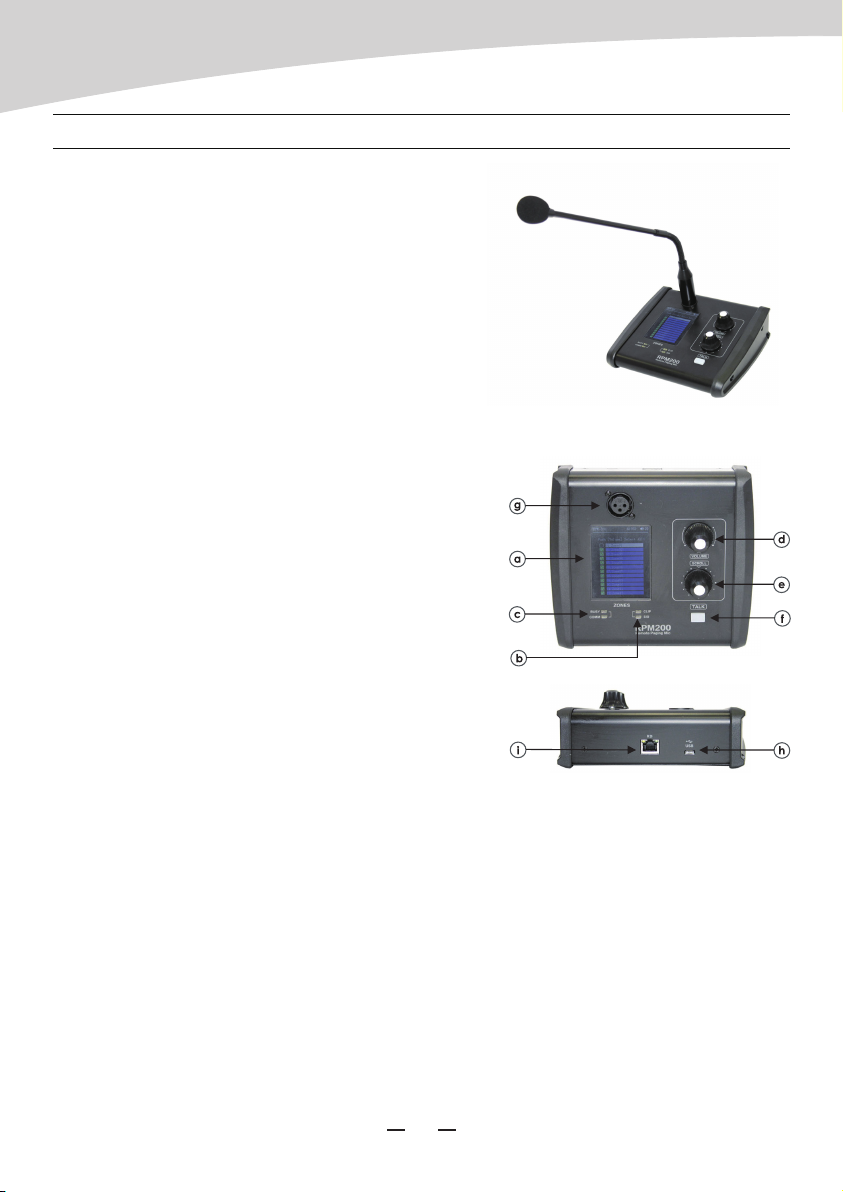
RPM200--Paging Station
RPM200 can manage the zones you want to be
broadcasted, the upper quantity is determinated by
the amount of the linked server host. And you can
choose the prelude as you wished (MP3 and wav are
supported, less than 12M.) Zones can be selected for
the ones needed or for all, it ensures the information
coverage and delivering selectivity at the same time.
a. LCD screen
It displays the selected zones, the volume and ID
number.
b. Signal status indicators
The green LED indicates the presence of signal when
the microphone is ON. The red LED indicates the limit
of clipping.
c. Communication status indicators
When the communication with the MATRIX-A8 is
correct, the green LED blinks.
In case of problem, the BUSY red LED lights up.
d. Volume control and all zone selector
It controls the volume of the microphone for each selected zones.
By pushing on the button, it selects all zones.
e. Zone selector
It selects one or several zones by turning the button left or right and pushing on it to
validate.
f. Push-to-talk switch
When the button is pushed, the chimes sounds and the red ring on the microphone lights
up indicating that one can talk.
BASIC OPERATION
7
AUDIO MATRIX

Volume adjustment
Turn “scroll” encoder to choose the zones intended to be tuned, short pushing to confirm,
rotating “Volume” encoder to change volume value of selected ones.(shows on the upper
right corner 0-32 can be adjusted) If all zones needed, just push “Volume” encoder once to
select all and turn the “Volume” encoder.
BASIC OPERATION
OPERATION
Insert the extended reticle terminal to RD port of remote device and the other end to the
serve host. Please note link with shield cat5e or better cable, the total length end to end
should be no more than 100m.
g. XLR connector
Female 3 pin XLR connector for the gooseneck electret microphone. It uses a phantom
power controlled by software.
h. USB port
This port is used to load MP3 files for chimes sound. The maximum time for the chimes is 4
seconds.
i. RD port
Connection to the MATRIX-A8. The maximum CAT 5e cable length is 100 meters.
PHYSICAL INSTALLATION
8
AUDIO MATRIX

Please use high rated network cable to connect the Ethernet port of PC and the LAN port of
serve host device. Then run MatrixSystemEditor, make sure the IP is linked rightly by the
remarks given by dialogs. At the main interface, you can drag the device in the left column to
the right area, that is the operation to add a device. Please make sure the device you added
is physically linked, or there would be no effects even if all settings are saved. Double click for
specific operation, here we add a RPM200.
If the device is connected properly, the gray rectangle in the left middle would turn to green.
OPERATION
SOFTWARE CONTROL
Broadcast
Turn “Scroll” encoder to choose the zones intended to be paged, choose the ones by
pushing “Scroll” encoder shortly and repeat until all the zones needed hooked. If all zones
needed, just push “Volume” encoder once to select all. After paging zones selected, click
the “Talk” button to speak, click again to stop. Normally, there is a chime sound before your
speech, you can change or cancel it by replacing or removing the inner sound file. (You
should connect the USB port to your computer to accomplish this work.) Please make
certain all the zone to be used are selected before speaking, if not, the system would
remind you “Select Zones First !” .
Rename zones
Holding the “volume” to enter the modifying interface, please note only alphabet, number,
common used symbol supposed.
Reset device
Holding “Volume” and “Scroll” encoder together more than 3 seconds to enter factory
resetting, “Load default setting …” would be showed on screen at the same time. The
device would restart automatically after process finished.
9
AUDIO MATRIX
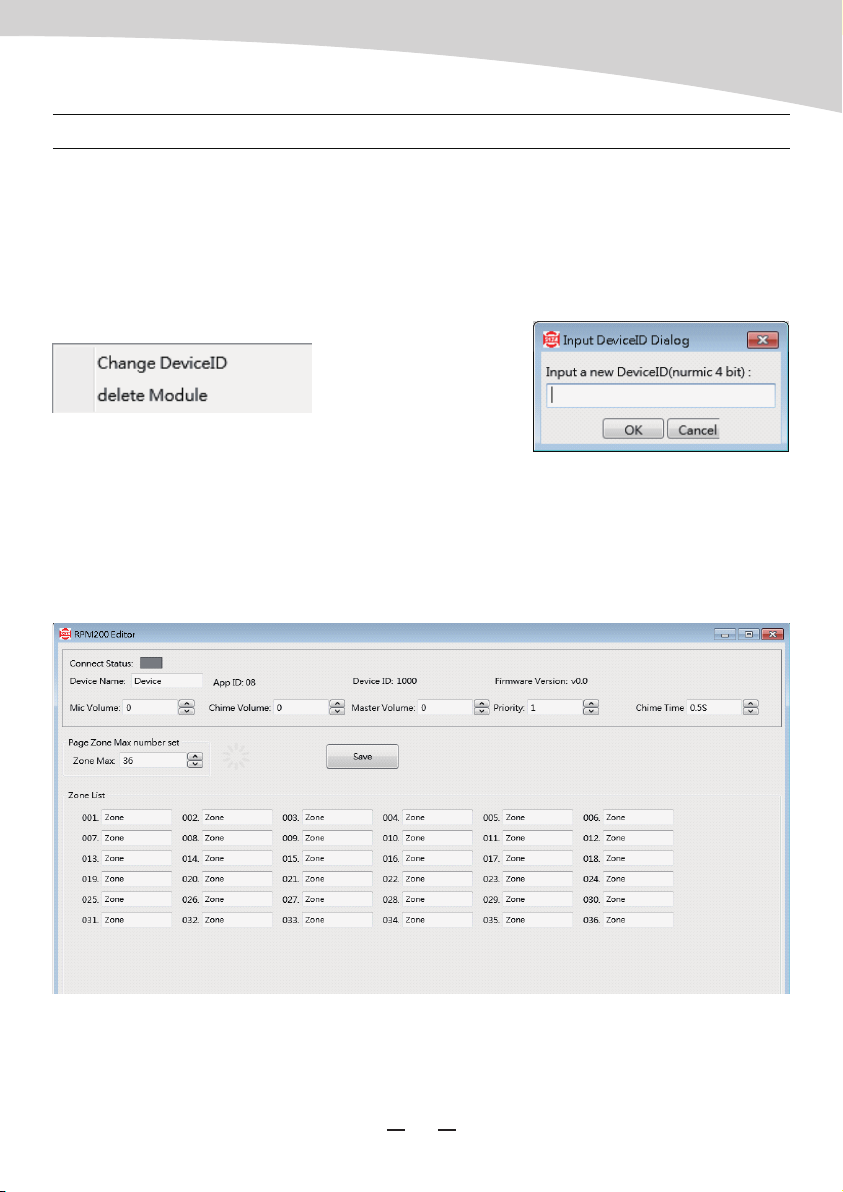
ID modification
Right click on the “DeviceID” position, the function menu popped up as shown; click
“Change DeviceID”, then enter the number(4 bit) you wanted in the text box, finally click OK
to save and to take effect.
Note: The first time to use the whole system, initial work to assign ID for each device is
necessary for its functioning.
Mic Volume
Click the upward icon next to the text box for turning up the volume, and the downward icon
for decreasing, 0-32 stage can be adjusted. Click “Save” button to take effect.
SOFTWARE CONTROL
10
Rename device
Double click on the device block to enter the page, “APP ID”, “Device ID”, “FirmwareVersion”
would show automatically according to the information of the device linked. Enter a name
into the “Device name” textbox and click “Save” button to take effect. Please make sure the
name can only consist of alphabets, numbers and common symbols.
AUDIO MATRIX
Master Volume
Same as the Mic Volume, 0-32 stage can be adjusted.
Priority
To define the priority of the device presented, 1-8 accepted, bigger for higher priority, click
“Save” button to take effect.
Chime Time
To define the time of Chime Sound, click upward and downward icon to adjust, 0.5 for
variation, 0.5-12S accepted, click “Save” button to take effect. If the chime sound not
uploaded, there would be no chime to be played.
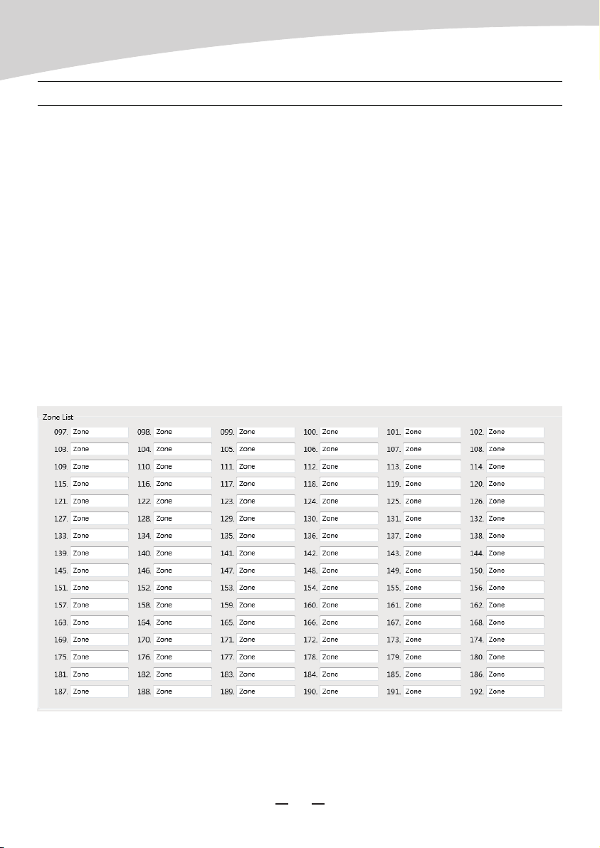
Zone List
To define the quantity of zones, click upward and downward icon to adjust, 12 for variation,
12-192 accepted, click “Save” button to take effect.
SOFTWARE CONTROL
11
AUDIO MATRIX
Attached
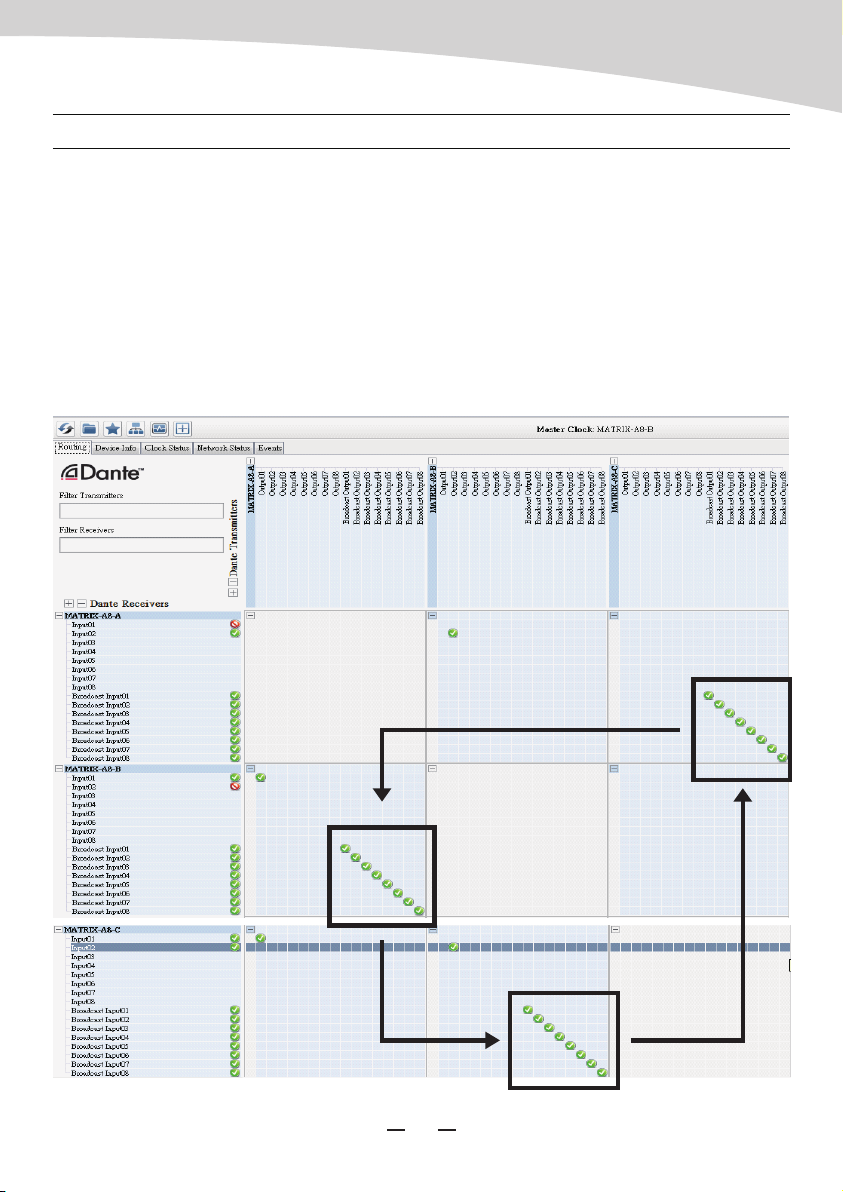
Configuration for multiple sever host linked :
Dante Control software is required for this action, please visit WWW.SEIKAKU.HK to
download.
After all the physical linkage confirmed, start the software and set tiks like below in the
indicated area. That is to assign the all Broadcast outputs of the pervious device to the all
Broadcast inputs of the next one, and so foth except the last ; for the last, we should connect
its Broadcast outputs back to the Broadcast inputs of the first one. Here is the example for
three host.
SOFTWARE CONTROL
12
Step3: MATRIX A8 C routing to MATRIX A8 A
Step1: MATRIX A8 A routing to MATRIX A8 B
Step2: MATRIX A8 B routing to MATRIX A8 C
AUDIO MATRIX

For more information about firmware, please visit WWW.SEIKAKU.COM. Please check the
hardware version twice to identify the compatibility of firmware tended to upgrade.
FIRMWARE UPDATE
a. There is no sound for the system
1). Please check if the device powered on, its screen lit or not.
2). Please make sure “Talk” button was pressed before voicing.
3). Please recheck the setting of MIC volume, make sure it was in a proper position.
4). Please check the channels assignment, make sure the one you output in hooked up with
the input at present.
5). Please the amplifier or active speaker on the circuit, make sure they are charged and set
appropriately.
6). Please make sure the entire system configuration is set rightly.
7). Please try to restart all the devices.
8). Please make sure all the physical connections are stable and right.
9). If all steps above checked, defects still exited, please insult the professional for help.
b. Sound seems to be abnormal
1). Please check the sound sources, low quality input always cause distortion and
resonance.
2). Please check the volume setting, consumption overloaded would cause distortion and
resonance either.
3). Please try to restart all the devices.
4). Please make sure all the digital linkages are adopted high quality shield cat5e network
cable or above, and professional cables for analog too.
5). If there some intermittent clipping sound, please check all the joint point are fixed well.
6). Please make sure devices and cables are not under high magnetic or high radical
environment.
7). Please make sure the furthest length form the sever host is no more than 100m. (150m
for the grounded linkage)
8). Please make sure the analog transmission also within the fidelity limitation.
9). If all steps above checked, defects still exited, please insult the professional for help.
FAQ
13
AUDIO MATRIX

c. Devices can not be found
1). Please make sure devices are linked well.
2). Please make sure all devices were assigned their unique ID with MatrixSystemEditor at the
initial configuration.
3). If this system using several sever hosts for extend linkage, please make sure the system
were set rightly by DANTE Controller. Please refer to “Configuration for multiple sever host
linked” part for details.
4). Please try to restart all the devices.
5). If all steps above checked, defects still exited, please insult the professional for help.
d. Software can not start
1). Please make sure the operating system version is later than Windows 7.
2). Please make sure NetFreameWork4.5.* suit is installed.
3). Please make sure no firewall or antivirus software affects their running.
4). Please make sure system acquired valid IP and shown no error.
5). If all steps above checked, defects still exited, please insult the professional for help.
MIC Input
• Active balanced
• Connector: 3-pin female XLR, ,(1 Gnd,2 Signal, 3 LED Power)
• Phantom Power: +12VDC @ 6mA
Indicators and switch
• LCD Display: Zone activation
• LEDs: Signal Status
• Switch: Push to Talk
Ports
• RD net to Matrix: RJ45, 100 m CAT 5e cable
• USB: For Chimes Sound file (4 seconds)
Dimensions
• L x H x D: 166 x 53 x 162 mm
FAQ
SPECIFICATIONS
14
AUDIO MATRIX
NF04945-1.0
Table of contents


