4EVAC 4E-CMT User manual

Hacousto Holland bv
Industrieweg 87
2651BC Berkel & Rodenrijs
4E-CMT installation and user guide
Author:
DD
Page 1of 13
SUMMARY
This document includes both installation and user guides of 4E-CMT, the commercial purpose microphone
station with touchscreen for the 4EVAC Voice Evacuation System. It explains how the 4E-CMT should be
installed and configured. The installation instructions are addressed to trained technical personnel, such as
installers, service technicians and commissioning engineers. The user instructions explain how to operate
the 4E-CMT and how to interpret indications by the end users as well as technical personnel, such as service
technicians.
REVISION AND APPROVAL
Rev.
Date
Nature of Changes
Approved By
01
04-09-2019
Original draft
DD
02
05-06-2020
Corrections
TvdH

Hacousto Holland bv
Industrieweg 87
2651BC Berkel & Rodenrijs
4E-CMT installation and user guide
Author:
DD
Page 2of 13
Table of Contents
1. What is the 4E-CMT? ............................................................................................................................................................. 3
2. Where do I start?..................................................................................................................................................................... 3
3. Configuration settings ........................................................................................................................................................... 4
4. Hardware installation and settings.................................................................................................................................... 5
L-Net .................................................................................................................................................................................. 5
4.1.1. Network ports................................................................................................................................................... 5
4.1.2. Redundant link ................................................................................................................................................. 6
4.1.3. Network cabling................................................................................................................................................7
Device ID........................................................................................................................................................................... 8
5. Front Panel................................................................................................................................................................................. 9
PAGING tab ..................................................................................................................................................................... 9
5.1.1. Zone selection .................................................................................................................................................. 9
5.1.2. Source selection............................................................................................................................................... 9
5.1.3. Start paging......................................................................................................................................................10
5.1.4. Stop message / BGM ....................................................................................................................................10
5.1.5. Silence zone .....................................................................................................................................................10
MORE tab ........................................................................................................................................................................ 11
LOG tab............................................................................................................................................................................ 11
6. Technical specifications........................................................................................................................................................12

Hacousto Holland bv
Industrieweg 87
2651BC Berkel & Rodenrijs
4E-CMT installation and user guide
Author:
DD
Page 3of 13
Thank you for choosing 4EVAC as your Voice Evacuation System solution.
4EVAC Compact 500 is an all-in-one Voice Evacuation System box. The box contains a completely
integrated Voice Evacuation System, capable of both standalone and network operation. 4EVAC Compact
500 is certified in accordance with EN54-16 and EN54-4, which are harmonized standards under the
Construction Products Regulation, mandatory in the European Union.
1. What is the 4E-CMT?
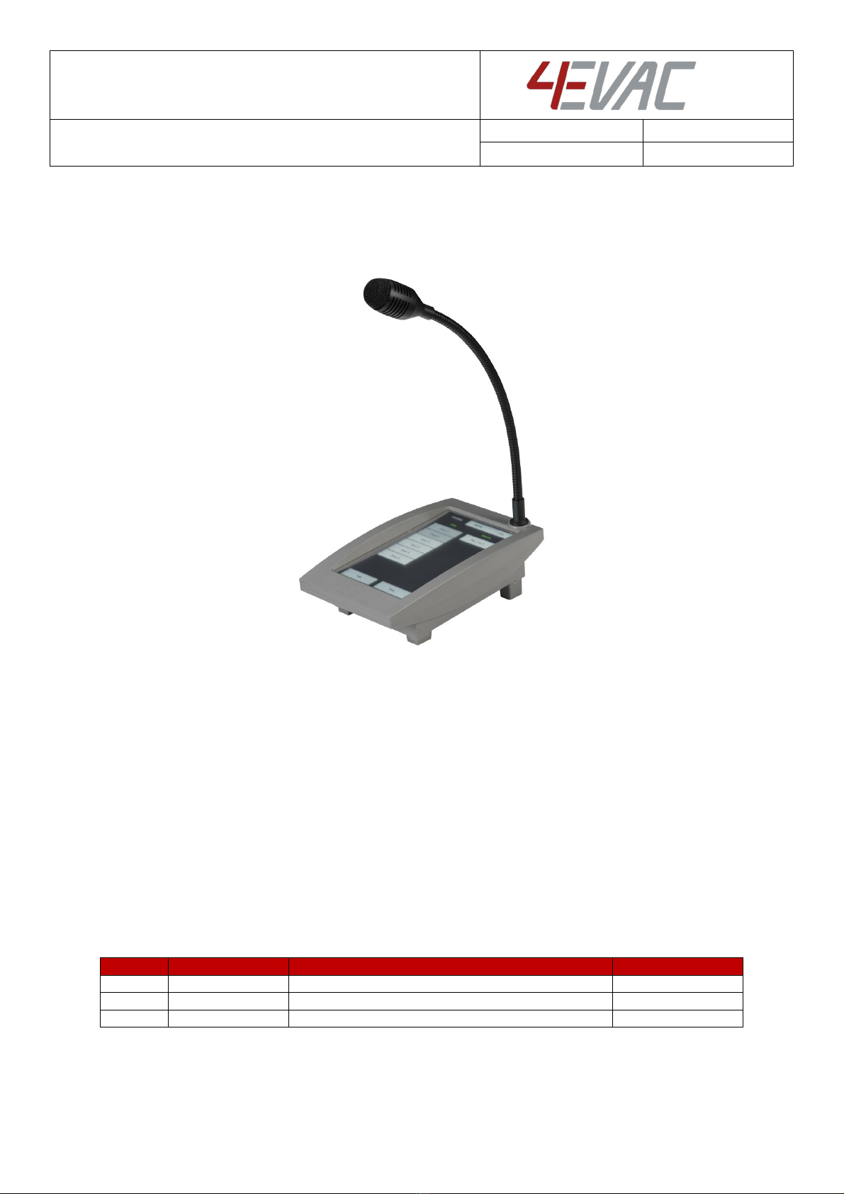
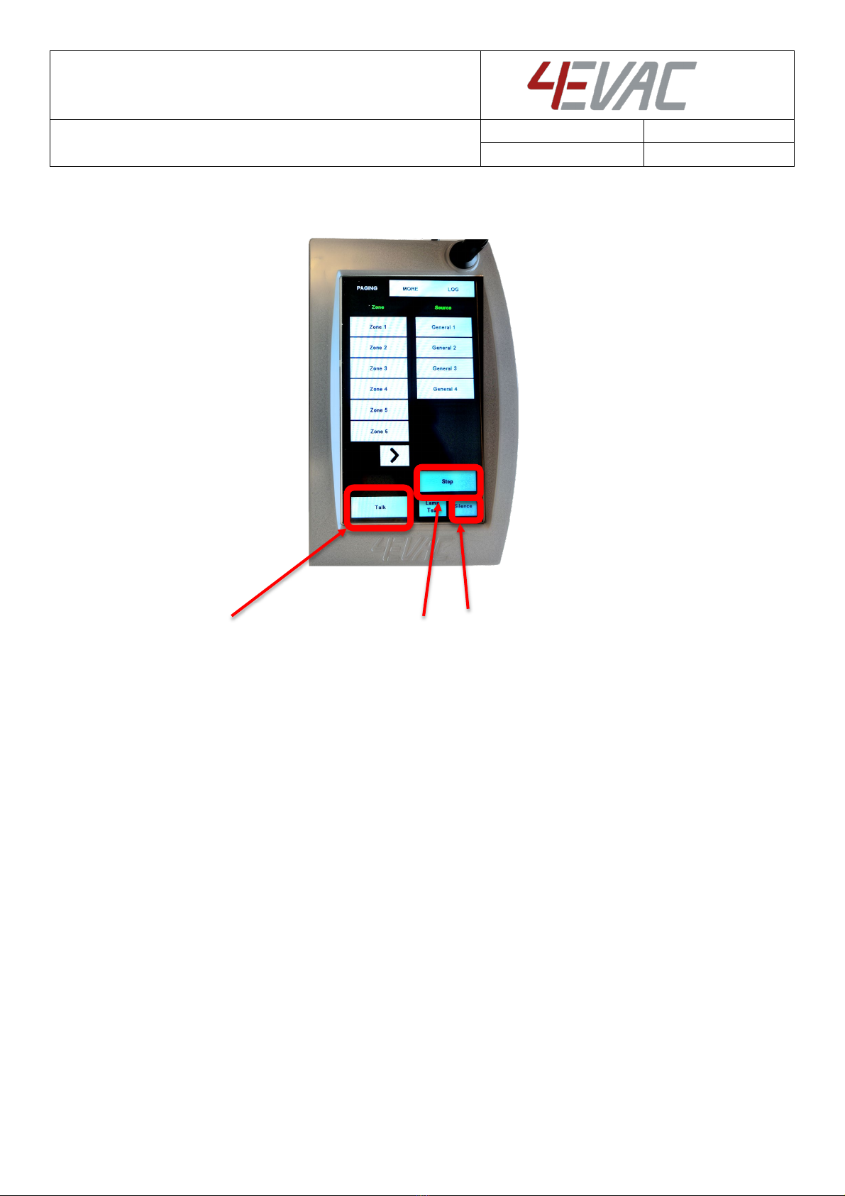
4E-CMT is a desktop/wall mounted microphone station with a touchscreen
panel. It can address up to 255 zones and trigger any general-purpose source
or message available in the entire system. 4E-CMT features a gooseneck
microphone for general paging.
4E-CMT offers general-purpose paging functions, where general messages,
BGM and paging features are available, as well as user defined non-emergency
events. 4E-CMT does not support microphone surveillance and does not offer
any emergency functions and is therefore not suitable as an EN54 compliant
emergency microphone.
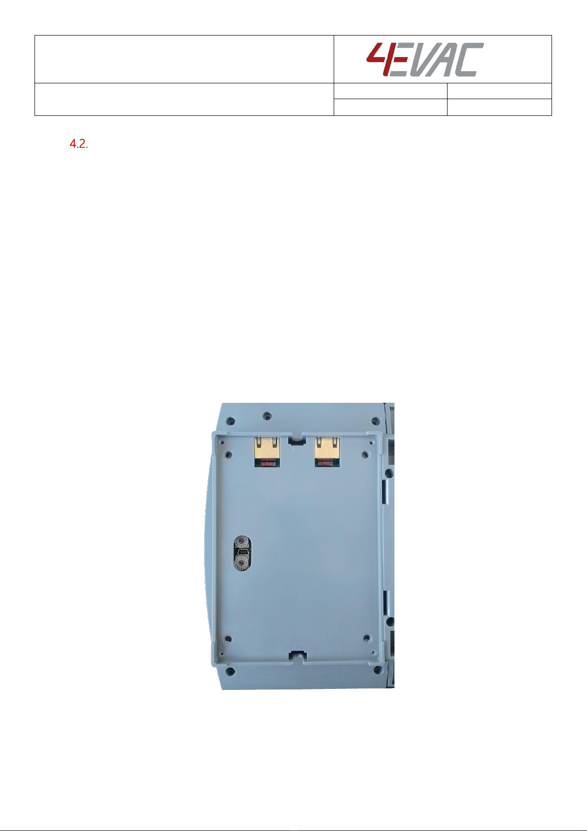
4E-CMT is connected to the L-Net interface of the 4EVAC system main unit and
may be daisy-chained with more L-Net devices. 4E-CMT is dedicated for call points where only general
purpose paging is required.
4E-CMT is compatible with all 4EVAC voice evacuation panels, including Compact 500 and Impact.
2. Where do I start?
First, make sure that you are officially allowed to access the hardware of Compact 500 system devices. This
is usually the case if:
you are an authorized representative of 4EVAC;
you have been trained by 4EVAC or one of its authorized representatives for installation, service
and commissioning of Compact 500 Voice Evacuation System.
Unauthorized hardware and/or software modifications are against the law and outside of the
manufacturer’s responsibility. If you have doubts about your status and access level permissions, please
contact the 4EVAC main office.

Hacousto Holland bv
Industrieweg 87
2651BC Berkel & Rodenrijs
4E-CMT installation and user guide
Author:
DD
Page 4of 13
Important note: Access level 3 explanation
Opening the device housing or tampering with the network cabling is
restricted. This gives access to all interfaces, internal system
connections and sensitive hardware settings that are of high
importance to system operation mode, hardware reliability and safety
(Access Level 3 according to EN54-16, Annex A). This access level (and
higher) is strictly protected by the manufacturer and reserved only for
service personnel which is trained, approved and officially certified by
the manufacturer. Any actions carried out in Access Level 3 without the
manufacturer’s explicit approval may lead to incorrect settings or
hardware damage, causing serious system malfunction, and therefore
are strictly prohibited and void manufacturer’s warranty.
3. Configuration settings
Settings for the 4E-CMT are included in the configuration file located on the micro SD memory card
installed in the 4EVAC system main unit.
This configuration file includes user-defined settings, such as:
-zone selection buttons;
-sources available for audio routing (BGM inputs, general purpose messages);
-microphone volume level,
-TALK button mode (PTT/toggle), etc.
The configuration file should be prepared in 4EVAC Manager. 4EVAC Manager is GUI software running on
Windows OS. More information about 4EVAC Manager can be found in the software manual “4EVAC
Manager guide”.
NOTE: Please make sure that the configuration file is prepared with the version of 4EVAC Manager
compatible with the firmware version of the system.
The installation file of the latest 4EVAC Manager and the manual are available at our website
www.4EVAC.com

Hacousto Holland bv
Industrieweg 87
2651BC Berkel & Rodenrijs
4E-CMT installation and user guide
Author:
DD
Page 5of 13
4. Hardware installation and settings
L-Net
4E-CMT is a remote station connected to the L-Net port of the C500 main unit. Multiple microphone
stations may be used in the same L-Net, with the following limitations:
A maximum of 8 stations per L-Net port
A maximum of 16 stations per single 4EVAC main unit (total sum of all 3 L-net ports)
The microphone station may also be daisy-chained together with other L-Net devices
Compact 500 L-Net (local network)
4.1.1. Network ports
4E-CMT offers 2 L-Net ports (RJ-45) for network connections to the 4EVAC main unit and distributed parts
of the 4EVAC Voice Evacuation System. Both L-Net ports are equal, therefore there is no difference between
which port is connected to which side of L-Net daisy-chain.
L-Net ports on the back side of 4E-CMT

Hacousto Holland bv
Industrieweg 87
2651BC Berkel & Rodenrijs
4E-CMT installation and user guide
Author:
DD
Page 6of 13
4.1.2. Redundant link
If you need to make a redundant L-Net connection to the Compact 500 main unit, connect both L-Net
ports of the device to two L-Net ports on the C500 main unit. You can choose any L-Net port on the C500
main unit. This creates a double daisy-chain of the redundant A/B power and data link to the device and
ensures fail-safe networking in case of a single cable or port failure.
Both spurs of the redundant A/B link may be populated with other L-Net devices.
NOTE: The device is equipped with a power link jumper, which, by default, is in the ON position (pass-
through power over L-Net). In order to a create redundant link, the jumper must be moved to the OFF
position. The device will then be immune to a single port short-circuit of the power bus.
When jumper 1 is closed (switch 1 on), the corresponding port 1 will pass through 24V DC from port 2 to
devices connected to port 1. Jumper 2 (switch 2) works accordingly, passing 24V DC received from port 1.
The power jumper should be used if the device is supposed to be connected via redundant link. In this case
the device must not pass power through towards the C500 on either of the 2 spurs of the redundant link.
Bottom view - location of power link jumpers
Power link jumpers.

Hacousto Holland bv
Industrieweg 87
2651BC Berkel & Rodenrijs
4E-CMT installation and user guide
Author:
DD
Page 7of 13
4.1.3. Network cabling
4EVAC network features a full duplex RS-422 data link and 24V DC power to remote devices.
If you’re building a distributed system using the 4EVAC network, you should make physical links between
devices using the right cables. Cabling should meet the following requirements:
1. Crossover twisted-pair cable (compatible with Ethernet crossover)
2. CAT5e or higher for maximum distance of 250m.
3. Non-CAT / lower than CAT5e: 250m not guaranteed.
4. Shield required (at least FTP)
NOTE: If you use a straight cable, the device will power up but the Tx/Rx data terminals will not be properly
connected. This will result in a communication fault between the L-Net device and the main controller unit.
The L-Net device will not be able to initialize, thus will remain in boot-sequence, not operational.
Caution! Use only crossover cables and keep correct the pinout! Connecting power pins to data pins will
damage the network port.
pin number pin number
GND shield shield GND
RX+ 1 1 RX+
RX- 2 2 RX-
TX+ 3 3 TX+
power + 4 4 power +
power - 5 5 power -
TX- 6 6 TX-
power + 7 7 power +
power - 8 8 power -
pin number pin number
GND shield shield GND
RX+ 1 1 RX+
RX- 2 2 RX-
TX+ 3 3 TX+
power + 4 4 power +
power - 5 5 power -
TX- 6 6 TX-
power + 7 7 power +
power - 8 8 power -
xover type A cable
xover type B cable

Hacousto Holland bv
Industrieweg 87
2651BC Berkel & Rodenrijs
4E-CMT installation and user guide
Author:
DD
Page 8of 13
Device ID
The microphone station needs an ID setting in order to be properly recognized in the network and operate.
If the device ID is duplicated or set to a wrong value, the device will not receive the correct configuration
settings from the main unit. In this case the remote station will be stuck in its boot sequence and remain
non-operational.
Device ID is set by means of two rotary switches, which define the two-digit hexadecimal value of the ID.
In order to check or set the Device ID, you must access the rotary switches on the back side of the unit:
1. Remove the steel plate covering back of the console.
2. Identify high-significant and low-significant rotary switches. The Device ID is a combination [HI LO]
of those two digits.
3. Make sure the ID value exists in your configuration settings, relates to the right device type and is
not duplicated to another device. Allowed values: 01-FE
4. Set the Device ID value according to the configuration settings of the 4EVAC system.
5. Plug-in the L-Net cable connecting the station with the 4EVAC main unit.
6. Observe the boot sequence which should see the unit automatically entering normal operating
mode afterwards.
7. Assemble the back plate (and optionally the rubber feet).
4E-CMT bottom view: Device ID setting
HIGH
LOW

Hacousto Holland bv
Industrieweg 87
2651BC Berkel & Rodenrijs
4E-CMT installation and user guide
Author:
DD
Page 9of 13
5. Front Panel
NOTE: 4E-CMT does not support emergency mode. Evacuation features are not available for this device.
As long as the system is activated in voice alarm condition (EVAC mode), all general paging features are
also not accessible.
PAGING tab
5.1.1. Zone selection
In order to start paging / message, first select a zone or group of zones on the left section of the screen.
If there are more than 6 zones accessible, use the scroll “arrow” button to scroll through pages with zone
selection.
5.1.2. Source selection
Next, on the right section of the screen, select the source to be transmitted to the selected set of zones.
Once selected, the source will be immediately routed to destination zones.
If there are more than 6 sources accessible, use the scroll “arrow” button to scroll through pages with source
selection.
Zone
selection
Source
selection

Hacousto Holland bv
Industrieweg 87
2651BC Berkel & Rodenrijs
4E-CMT installation and user guide
Author:
DD
Page 10 of 13
5.1.3. Start paging
Use the TALK button to start paging in selected zones.
If no zones are selected, pressing the TALK button will start paging in all zones available on this panel (ALL
CALL).
5.1.4. Stop message / BGM
Select zones where a message / BGM audio signal is being transmitted and press STOP. This will reset these
zones, stopping all audio streams transmitted to these zones.
5.1.5. Silence zone
Select zones where you need to suppress sound and press SILENCE. This will silence selected zones,
suppressing audio. Repeat the same sequence to re-enable sound.
TALK
button
STOP
button
SILENCE
button

Hacousto Holland bv
Industrieweg 87
2651BC Berkel & Rodenrijs
4E-CMT installation and user guide
Author:
DD
Page 11 of 13
MORE tab
Under the “MORE” tab you will find buttons used for starting and stopping user programmable events, for
example: starting transmission of pre-defined BGM input to a pre-defined group of zones.
For more information about programming events, please look in the user manual of the 4EVAC Manager,
where all configuration settings are explained.
LOG tab
Under the “LOG” tab you will find the system log, which shows a list of the 200 most recent system events
that occurred since the last system reboot. The system log displays information collected from the entire
system network, including:
-Start / stop of events
-Start / stop of paging / live EVAC status
-Fault codes (individual for each device in the network)

Hacousto Holland bv
Industrieweg 87
2651BC Berkel & Rodenrijs
4E-CMT installation and user guide
Author:
DD
Page 12 of 13
6. Technical specifications
4E-CMT
Number of zones
max. 255 zones (global network access)
Controls and indications
RGB touchscreen witch user-configurable buttons: zone / group selection,
sources, events, fault/event logging
Microphone (dual)
General paging
Condenser, gooseneck
Emergency
MEMS transducer, handheld, monitored
Power consumption
24V (L-Net)
max. 180mA
Audio
Frequency response
100 Hz – 12 kHz
Digital audio format
24 kHz sampling, ADPCM compressed
Audio processing
Fixed BP filter, fixed dynamics compression
Local network interface
Architecture
Master-slave, up to 16 slave devices per C500 main unit
Connection
RJ-45, powered daisy chain, digital audio & control data
Cabling
X-over FTP CAT5e (or higher)
Current rating via single link
max. 500 mA (up to 8 slave devices) via L-Net port,
Max. length of L-Net link
250 m
Mechanical
Base dimensions (HxWxL)
6 x 13 x 21 cm
Gooseneck mic length
31.5 cm
Weight
850 g
Housing material
Steel / ABS
IP rating
IP 30
Mounting
Desktop wedge / wall-mounted (incl. wall bracket)
Operating conditions
Temperature
10–40°C
Relative humidity
max. 90% (non condensing)
Storage temperature
-40–70°C

Hacousto Holland bv
Industrieweg 87
2651BC Berkel & Rodenrijs
4E-CMT installation and user guide
Author:
DD
Page 13 of 13
MADE IN THE NETHERLANDS
4EVAC is a trade name of:
Hacousto Holland bv
Industrieweg 87
2651BC Berkel & Rodenrijs
The Netherlands
www.4EVAC.com
Table of contents
Other 4EVAC Microphone manuals