3
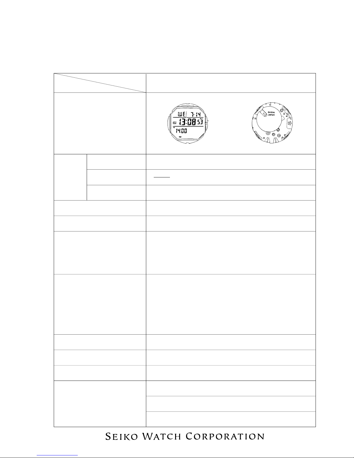
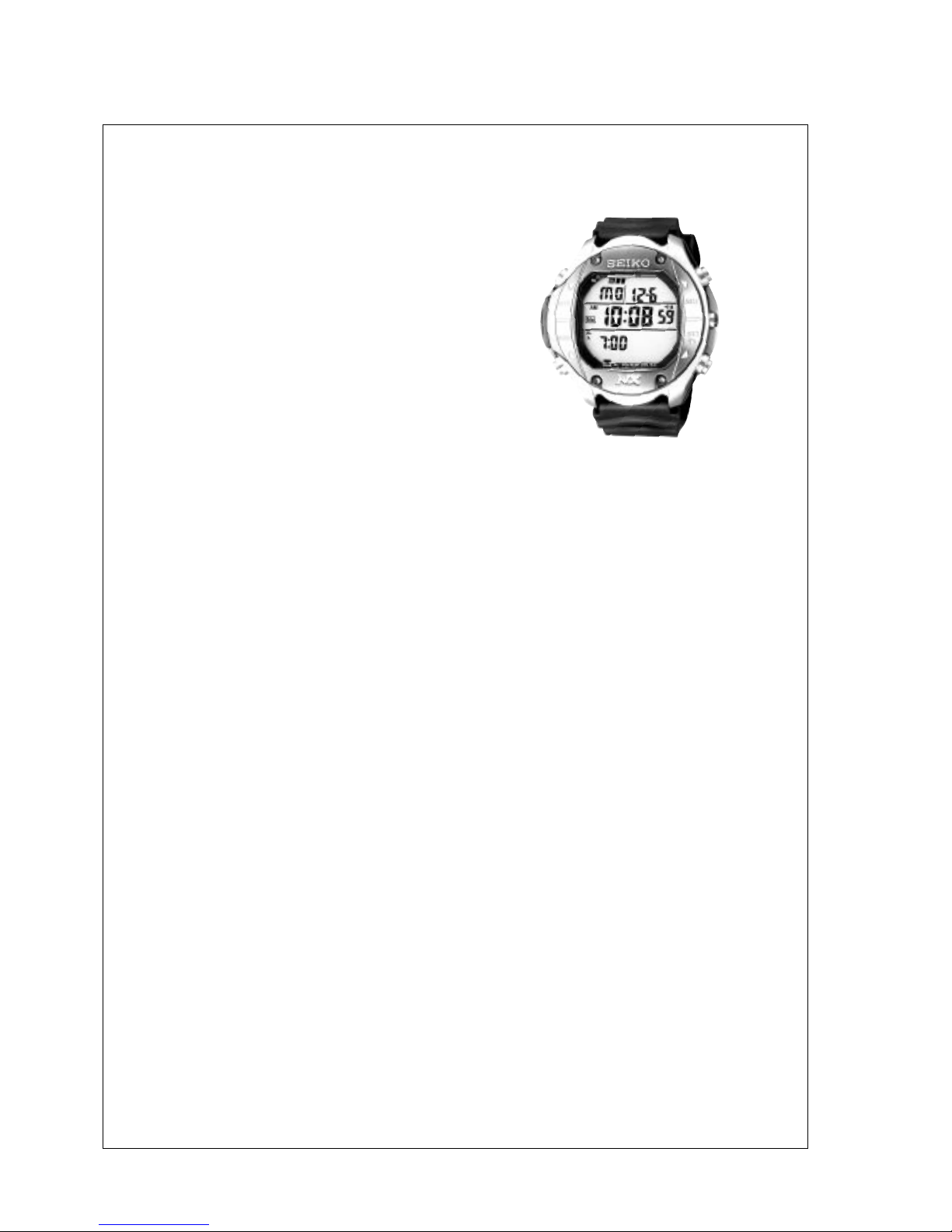
TECHNICAL GUIDE Cal. DH33A
I. REMARKS ON BATTERY CHANGE
When changing the battery, follow the procedures below.
<How to remove>
1. Remove the comment seal.
*Check where the comment seal was put, as it must be put
back to the same place.
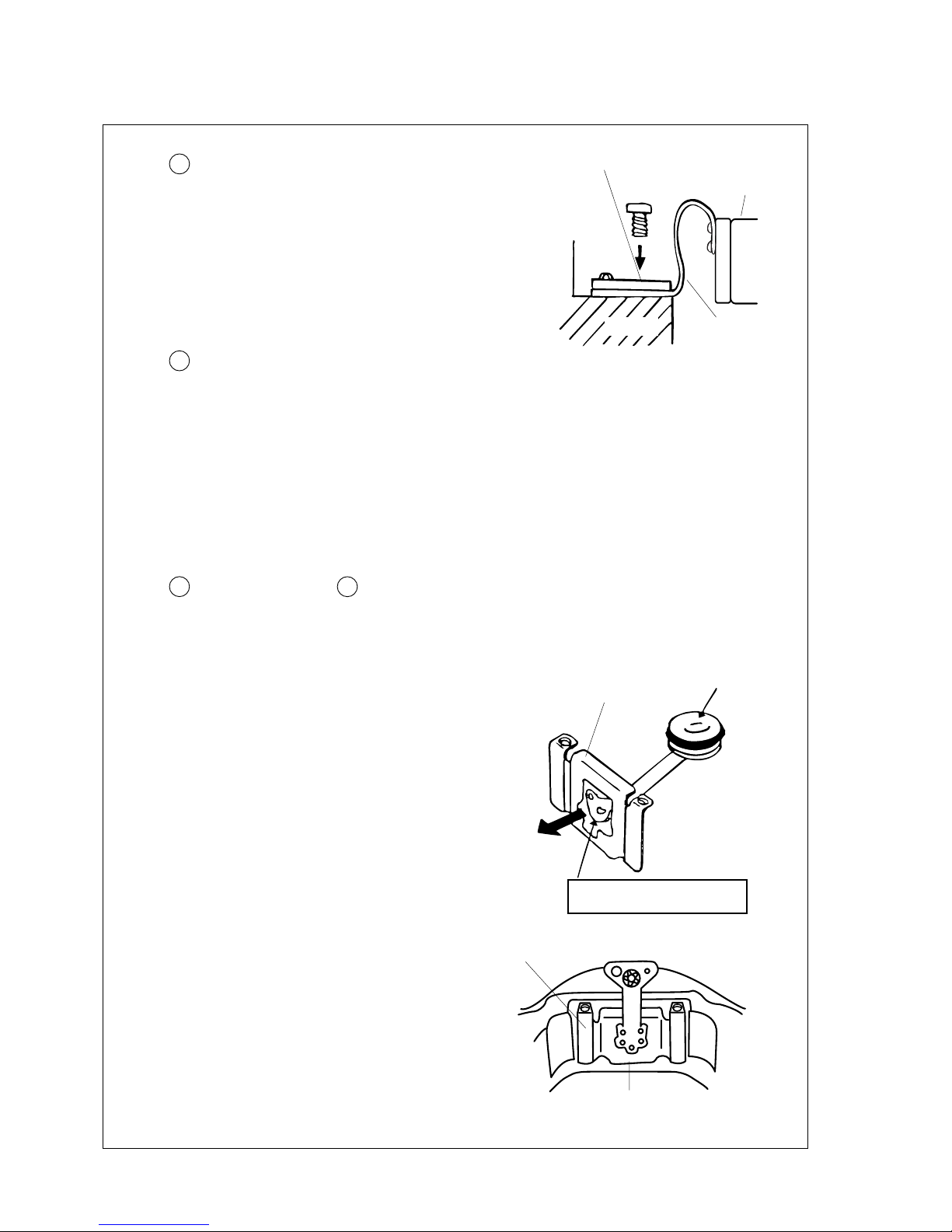
2. Release the battery clamp hooking portion with a pair of
tweezers as illustrated at right.
3. Remove the battery.
<How to install>
1. Set the new battery.
2. Set the hooking portion of the battery clamp firmly.
3. Put the comment seal back where it was originally put.
4. Reset the circuit by pressing down the AC terminal of the
circuit block and the circuit block cover with a pair of conductive
tweezers.
Battery clamp
hooking portion
II. REMARKS ON DISASSEMBLING AND REASSEMBLING
●Remarks on the adhesive
• The case back screw is fixed by using the adhesive.
•Use the “LOCTITE 241” of Loctite Corporation to fix the screws.
•Never use any other adhesive but “LOCTITE 241” in the market place or any joining material for band
adjustable screw (S-312), otherwise it may cause difficulties when unscrewing or poor water
resistance when screws become loose because of some unexpected shocks.
●How to glue and fix the screws
1. Remove water drops, oil contents, dust and dirt from the
screw and screw hole on the case.
2. Apply appropriate amount of the adhesive to a screw as
illustrated at right.
3. Tighten up the screw securely with a torque driver (bit size:
T5).
4. Leave them for approximately 24 hours under normal
temperature so that the adhesive becomes dry enough and
the screws get fixed securely.
1Case Back Screw
•When tightening the screws up, tighten the screw one after
another in diagonal order.
•After tightening up all the screws, retighten all of them once
again to fix them even more securely.
Adheshive