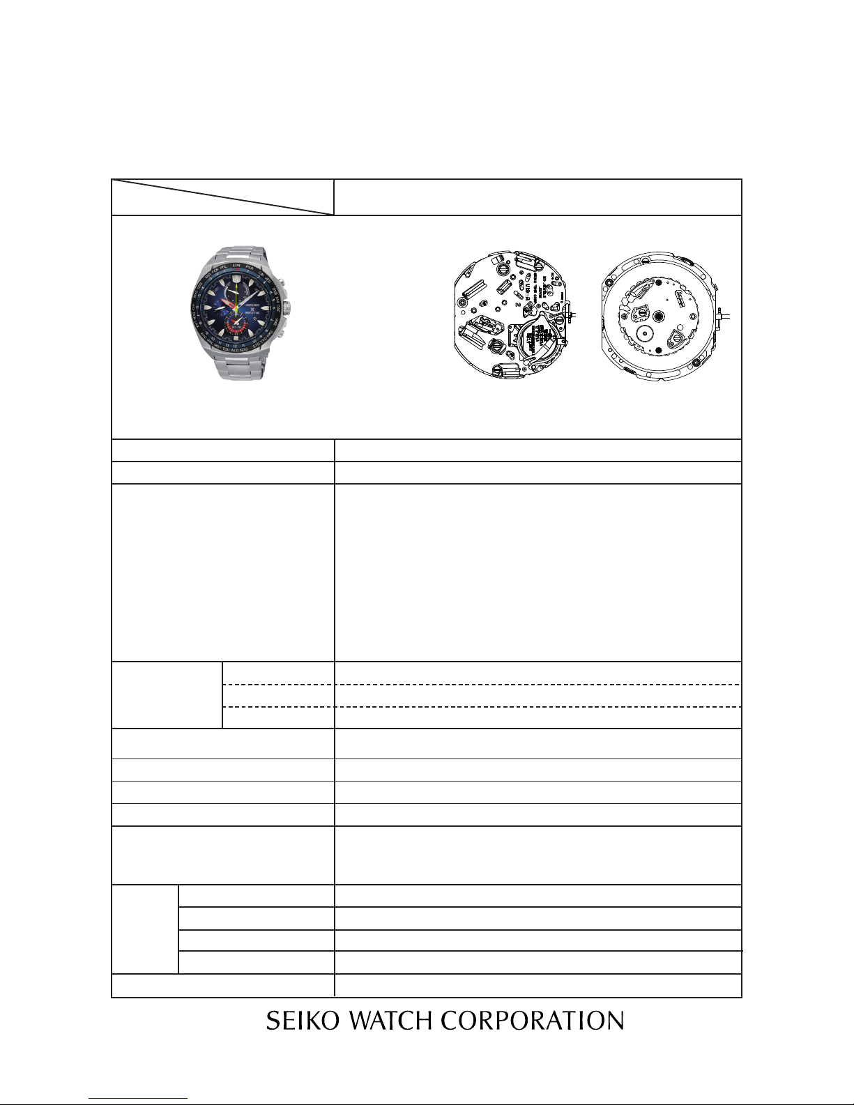
Seiko V195A Quick start guide

PARTS LIST /TECHNICAL GUIDE
ANALOGUE SOLAR Cal. V195A
[SPECIFICATIONS]
1/24
Item Cal. No. V195A
Power reserve
Driving system
Additional function
Crown operation
Loss/Gain
Regulation system
Number of jewels
Normal position
1st click position
Current consumption
Gate time for rate measurement
Power
supply
Motion of the second hand
Coil resistance
Power generator
Rechargeable battery
Operating voltage range
2nd click position
One-second intervals
Stepping motor 4 pieces
Diameter: Outside 27.6 mm
Casing 27.0 mm
Height: 4.4 mm
3 hands (hour, minute, small second hands)
Calendar display
Stopwatch (second, hour, minute)
Small alarm display (hour, minute)
Energy depletion forewarning function (The second hand moves at two-
second intervals.)
Overcharge prevention function
Power reserve indicator
Electronic circuit reset function
Second hand stop function
Daily alarm
Instant setting device for calendar
System reset function
World time function
Stopwatch function..........60-minute stopwatch in 1/5-second increments
(Auto stop measuring at 60 minutes)
Accumulated elapsed time measurement
Split time measurement
Single-time alarm function
Stopwatch hand position adjustment
Stopwatch, Power reserve display
Time setting, Setting “0” of stopwatch hand, System reset
Monthly rate:less than 15 seconds (worn on the wrist at temperature range
between 5 to 35 degrees Centigrade)
Use 10-second gate
Nil
Solar power generation system
Movement: less than 0.95 μA Circuit block: less than 0.30 μA
4002 567 1.40 - 1.80 kΩ
(COIL BLOCK) (COIL BLOCK FOR CHRONOGRAPH 1/5 - SECOND)
4002 568 1.30 - 1.70 kΩ
(COIL BLOCK FOR INDICATOR) (COIL BLOCK FOR ALARM)
MT920 Manganese titanium-lithium rechargeable battery
0.90V - 2.10V
From full charge to stoppage: Approximately 6 months
Nil
Time setting of alarm, Calendar setting

SPECIFICATIONS
2/24
Cal. V195A
FEATURES
The Cal. V195A is a solar alarm chronograph epuipped with a calendar function.
l Solar power generation system
The watch operates while charging electricity by converting light received on the dial to
electrical energy. It lasts for 6 months after full charge.
l Energy depletion forewarning function
When the energy stored in the rechargeable battery is reduced to an extremely low level, the
second hand starts moving at 2-second intervals instead of the normal 1-second intervals.
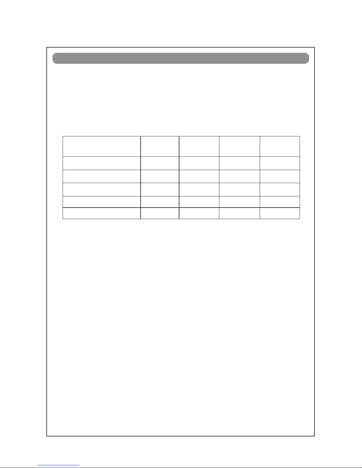
l Guideline of charging time
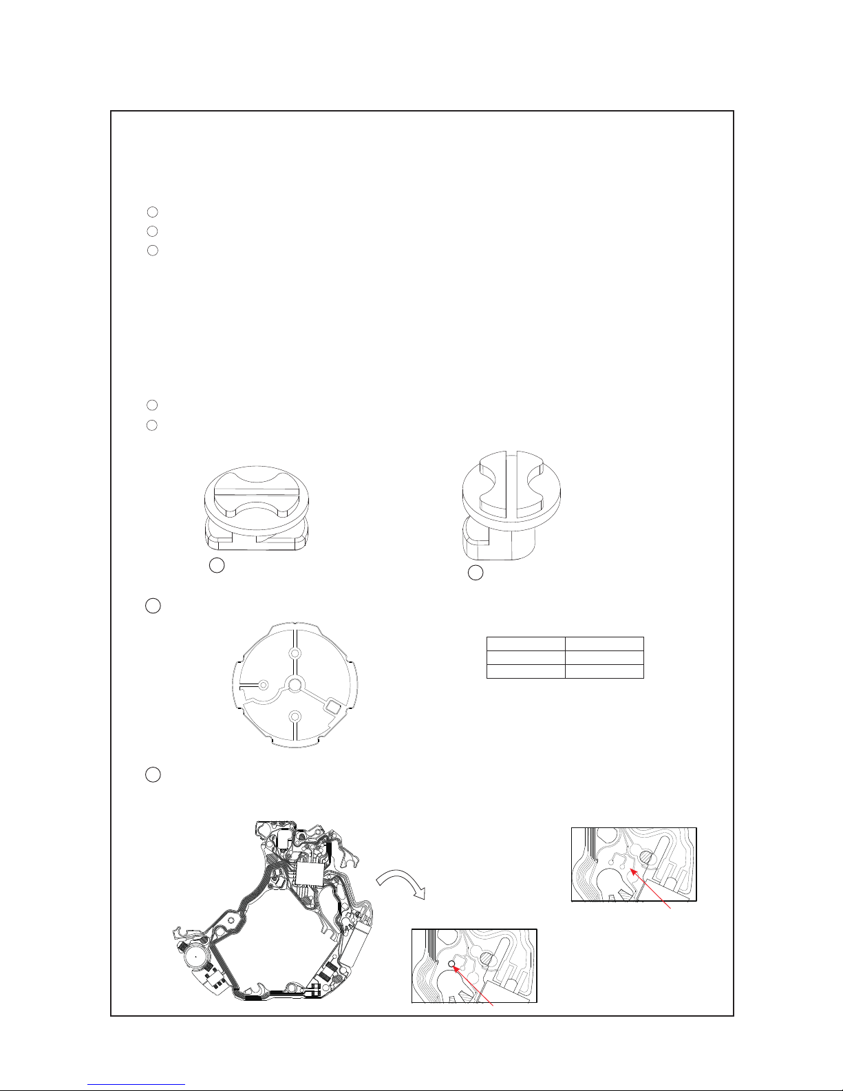
Environment/Light source Illumination
(lux)
Time required
for full charge
Time required
for steady
operation
Time to charge
1 day of power
General offices/ Fluorescent
Light
700 -60 hours 150 minutes
30W 20cm/Fluorescent light 3,000 110 hours 13 hours 33 minutes
30W 3cm/ Fluorescent light 10,000 30 hours 3.5 hours 9 minutes
Cloudy weather/Sunlight 10,000 30 hours 3.5 hours 9 minutes
Fair weather/Sunlight 100,000 5 hours 0.6 hours 2 minutes
The above table provides only a general guideline.
It is recommended that the watch be charged for as long as the charging time according to the
column "Time required for steady operation" in this table in order to assure the stable movement
of the watch.
l Caution for charging
When charging the watch, do not place it too close to a photo flash light, spotlight, incandescent
light or other light sources as the watch temperature will become extremely high, causing damage
to the parts inside the watch.
When exposing the watch to sunlight to charge it, do not leave it on the dashboard of a car, etc.
for a long time, as the watch temperature becomes extremely high.
While charging the watch, make sure the watch temperature does not exceed 60 °C.

Order of disassembly: 1
Order of assembly: 1
Lubricating:
Types of oil Oil quantity
AO-3 Normal quantity
1
2
3
4
5
6
AO-2
67
67
Piezoelectric Element 4589 801
Case Back
Case Back Gasket
Hour, Minute
and Small
Second Hands,
Chronograph
Hands (Hour,
Minute and 1/5
Second), Mode
Indicator Hand
Dial
Spacer for Solar Cell
4453 500
Solar Cell
4025 569
Holding Ring for Dial
0866 ***
Contact Point Spring
2pcs.
4281 516
Crown
Case
Movement
Anti Magnetic
Shield Plate B
4259 519
PARTS LIST Cal. V195A
3/24

14
7
8
10
12
15
Guide Plate Fixing Pin for
Calendar Correction
0027 973
11
13
9
20
16
Guide Plate for Calendar
Correction
4288 500
17
3rd Intermediate Wheel for
Calendar Correction
0962 504
18
2nd Intermediate Wheel for
Calendar Correction
0962 504
19
1st Intermeidate Wheel for
Calendar Correction
0962 580
Date Dial Guard
Screw (2pcs.)
0012 354
Date Dial Guard
0808 523
Date Dial
0878 ***
Date Dial Guide Plate Screw
0012 354
Guide Plate for Date Dial
0712 507
Date Corrector Setting Wheel
0737 505
Date Driving Wheel
0802 580
24-Hour Wheel for Alarm
0278 503
Hour Wheel
0271 636
Cal. V195A
PARTS LIST
4/24

21
Battery Clamp Screw(3 pcs.)
0022 230
27
Friction Spring for Second
Counting
0396 580
29
Buzzer Lead
Terminal
4246 527
22
Rechargeable Battery Clamp
4225 677
23
Rechargeable Battery Block
3023 24D
24
Circuit Block Cover Screw(3 pcs.)
0022 459
25
Circuit Block Cover
4461 599
26
Conducting Plate
4224 525
28
Circuit Block
4000 970
PARTS LIST Cal. V195A
5/24

40
Indicator Wheel
0902 502
44
Minute Wheel for Alarm
0264 580
39
Intermediate Wheel for
Indicator
0950 590
37
First Intermediate
Wheel for 1/5- Second
0885 590
30
Pin for Train Wheel
Bridge
0027 974
31
Train Wheel Bridge
0125 527
32
1/5-Second Counting Wheel
0888 501
34
Fourth Wheel and Pinion
0241 583
35
Third Wheel and Pinion
0231 580
38
Second Intermediate Wheel
for 1/5-Second
0885 591
41
Minute Wheel
0261 580
43
Center Wheel for Alarm
0902 502
33
Small Second Wheel
0240 521
42
Intermediate Wheel for
Alarm
0950 590
36
Fifth Wheel and Pinion
0701 581
Cal. V195A
PARTS LIST
6/24

52
Chronograph 1/5-Second
Rotor
4146 710
48
Coil Block for
Indicator
4002 568
46
Coil Block
4002 567
47
Coil Block for Chronograph
1/5-Second
4002 567
51
Step Rotor
4146 710
53
Indicator Rotor
4146 710
56
Setting Wheel
0281 580
58
Clutch Wheel
0282 585
60
Spacer for Center
Wheel and Pinion
4283 581
63
Rotor Stator
4239 710
64
Rotor Stator for
Chronograph
1/5-Second
4239 711
65
Rotor Stator for Indicator
4239 713
45
Coil Block for Alarm
4002 568
50
Alarm Rotor
4146 710
49
Switch Lever A
4450 703
54
Setting Lever
0383 592
55
Yoke
0384 583
57
Setting Stem
0351 586
59
Train Wheel Setting Lever
0391 591
61
Center Wheel and Pinion
0221 604
62
Rotor Stator for Alarm
4239 713
66
Switch Lever B
4450 701
67
Main Plate
0100 579
PARTS LIST Cal. V195A
7/24

57
GUIDE PLATE FIXING PIN FOR CALENDAR CORRECTION 0027 973
PIN FOR TRAIN WHEEL BRIDGE 0027 974
15
30
15 0027 973 30 0027 974
Cal. V195A
PARTS LIST
8/24
l
How to find the correct parts, if not determined by 4 digit caliber number
Following parts are determined based on the design of watches, such as hands height, dial color,
and design of cases. Please refer to the SEIKO WATCH PARTS CATALOGUE in order to choose
the corresponding parts.
5HOLDING RING FOR DIAL 0866 ***
9DATE DIAL 0878 ***
SETTING STEM 0351 586
The type of HOLDING RING FOR DIAL is determined based on the design of cases.
Check the case number and refer to the "SEIKO WATCH PARTS CATALOGUE" to choose the
corresponding parts.
l
How to find the correct pins
Please choose the corresponding pins.
Refer to the following figures.
4 SOLAR CELL 4025 556
Cal. Parts Number
V198A 4025 556
V195A 4025 569
28 CIRCUIT BLOCK 4000 970
Make sure to hole position on a CIRCUIT BLOCK for V195A in order to distinguish from others.
Cal. V195A
Cal. V198A
No hole
Hole
Note: Sollar cell differs according
to each caliber.
No hole

PARTS LIST Cal. V195A
9/24
lTools and consumables required for disassembling/reassembling
•Movement holder
UNIVERSAL MOVEMENT HOLDER (S-682)
• Watch oils
SEIKO watch oils (AO-3 and AO-2) and SEIKO watch grease S-6
AO-3 AO-2
S-6

TECHNICAL GUIDE Cal. V195A
10/24
REMARKS ON DISASSEMBLING AND REASSEMBLING
Set the notched portions of the dial to the guide posts (4 posts)
of the HOLDING RING FOR DIAL, and check that the dial is fixed
in position.
• How to install
1HANDS
• How to install
2DIAL
* Match the polarity of the ROTORs for stopwatch and alarm,
and then install the hands.
Check that the voltage of rechargeable battery exceeds 1.2 V
and the watch is working.
*Crown position: normal position.
Short-circuit in touching the AC pattern and the Rechargeable
Battery Clamp with tweezers (refer to the Fig. 1).
In order to match the polarity of the ROTORs, pull out the crown
to the second position, then short-circuit in touching the Pattern
A and the Rechargeable Battery Clamp with tweezers (refer to
the Fig. 2).
Install the Mode indicator hand at “E” position and the Alarm
(hour / minute) hands at “12” position.
Install the Small second hand, the Hour hand, the Minute hand
and the Chronograph second hand at “0” position.
Fig. 1
Fig. 2
3SPACER FOR SOLAR CELL
Set the notched portions of the SPACER FOR SOLAR CELL to
the guide posts (5 posts) of the HOLDING RING FOR DIAL, and
check that the dial is fixed in position.
• How to install
5
5
pattern A

④SOLAR CELL
⑤HOLDING RING FOR DIAL
* It is not necessary to separate the SOLAR CELL and the HOLDING RING FOR DIAL except in the case
that a part needs to be replaced.
• Disassembling and Reassembling of HOLDING RING FOR DIAL
<Disassembling>
1. The HOLDING RING FOR DIAL is fixed to the movement by the
hooking portion at 4 o’clock and 11 o’clock positions.
2. Insert the tip of a screwdriver into the gap between the hooking
portion and MAIN PLATE as shown with arrow marks in the
illustration to release the hooking portion from the main plate.
<Reassembling>
1. Set the 2 hooking portions to 4 o’clock and 11 o’clock positions
as shown in the illustration.
2. Gently push the hooking positions of HOLDING RING FOR
DIAL so that they catch the MAIN PLATE securely.
• Disassembling and Reassembling of SOLAR CELL
* Do not apply excessive force to the SOLAR CELL.
<Disassembling>
As there are 2 connection parts of the HOLDING RING FOR DIAL,
release them side by side.
<Reassembling>
Set the SOLAR CELL to 3 guide posts, and assemble it to the
HOLDING RING FOR DIAL by expanding the hooking portion
as shown in the illustlation.
TECHNICAL GUIDE Cal. V195A
11/ 24
REMARKS ON DISASSEMBLING AND REASSEMBLING THE MOVEMENT

DATE DIAL GUARD
< Lubrication >
Lubricate DATE JUMPER and the tooth tips of DATE DIAL.
screw
screw
guide post
8
• Reassembling
Set the Rechargeable Battery Guard to the guide posts (2
posts), and then tighten the Rechargeable Battery Guard
Screws (3 pcs).
RECHARGEABLE BATTERY CLAMP
22
AO3
screw
guide post
TECHNICAL GUIDE Cal. V195A
12/24

RECHARGEABLE BATTERY BLOCK
• Reassembling
Set the notched portion of the Rechargeable Battery Block to the guide post, and check that the
hooking portion of the Rechargeable Battery Block touches the (-) output terminal of the Circuit
Block.
hooking portion
guide post
(-) input terminal
23
* Slide the Rechargeable Battery Block under
the hooking portion of the Rechargeable
Battery Guard if it is after setting the
Rechargeable Battery Guard.
TECHNICAL GUIDE Cal. V195A
13/24

CIRCUIT BLOCK COVER
• Disassembling
1. Loosen the 3 CIRCUIT BLOCK COVER SCREWs.
2. Release the 4 hooking portions of the CIRCUIT BLOCK COVER (indicated by the arrows in the
illustration below.)
• Reassembling
1. Have the four hooking portions of the CIRCUIT BLOCK COVER (indicated by the arrows in the
illustration below) catch the movement securely. In doing so, check if the circuit block is set properly
to guide posts “a” and “b,” and reset it in position if necessary.
2. Tighten the 3 CIRCUIT BLOCK COVER SCREWs. When tightening the screws, take care not to cut
the coil.
c
b
a
screw
screw
screw
CONDUCTING PLATE
• Reassembling
Put the CONDUCTING PLATE on the CIRCUIT
BLOCK as shown in the illustration, and secure
it with the 2 guide posts.
guide post
guide post
25
26
TECHNICAL GUIDE Cal. V195A
14/24

FRICTION SPRING FOR SECOND COUNTING
• Reassembling
Slide a part of the SECOND HOLD SPRING under the TRAIN WHEEL BRIDGE.
CIRCUIT BLOCK
• Disassembling
Taking care not to damage the CIRCUIT BLOCK,
remove it from the posts of the TRAIN WHEEL
BRIDGE and the screw pins of the MAIN PLATE
(refer to a, b, c, d and e in the illustration).
• Reassembling
Set the guide holes of the CIRCUIT BLOCK
(refer to a, b, c, d and e in the illustration) to
the posts of the TRAIN WHEEL BRIDGE and the
screw pins of the MAIN PLATE.
ea
b
c
d
27
28
TECHNICAL GUIDE Cal. V195A
15/24

PIN FOR TRAIN WHEEL BRIDGE
• Disassembling
Turn the PIN FOR TRAIN WHEEL BRIDGE counter clockwise by 90 degrees, and loosen it.
• Reassembling
Set the PIN FOR TRAIN WHEEL BRIDGE as shown in the illustration, and tighten it by turning
clockwise by 90 degrees. (Refer to the Fig. 1.)
<Lubrication>
After fastening the PIN FOR TRAIN WHEEL BRIDGE, lubricate the upper part of the pivots of the
following parts (refer to the Fig. 2):
• 4 ROTORs: AO-2
• MINUTE WHEEL: AO-3
• SMALL SECOND WHEEL: AO-3
• INDICATOR WHEEL: AO-3
• ALARM MINUTE WHEEL: AO-3
• 1/5 - SECOND COUNTING WHEEL: AO-3
AO2
AO3
30
TECHNICAL GUIDE Cal. V195A
16/24
TRAIN WHEEL BRIDGE
• Reassembling
1. Check the setting positions of the WHEELs and ROTORs carefully. Be sure to check that lower
pivot of rotors are set to the MAIN PLATE properly.
2. Pull out the SETTING STEM to the 1st click position.
3. Install the TRAIN WHEEL BRIDGE carefully. If the BRIDGE can not be installed smoothly, recheck
the setting position of WHEELs and ROTORs as some parts may be set in the wrong position.
<Setting position>
Refer to the illustration in the next page.
31
Fig. 1
Fig. 2

TECHNICAL GUIDE Cal. V195A
17/24
● How to identify the gear train parts
33
Small Second
Wheel
0240 521
36
Fifth Wheel and
Pinion
0701 581
37
First Intermediate
wheel for 1/5-Second
0885 590
39
Intermediate wheel
for Indicator
0950 590
40
Indicator Wheel
0902 502
43
Center Wheel for
Alarm
0902 502
32
Calendar Wheel
0888 501
34
Fourth Wheel and
Pinion
0241 583
35
Third Wheel and
Pinion
0231 580
38
Second Intermediate
Wheel for 1/5-Second
0885 591
41
Minute Wheel
0261 580
44
Minute Wheel for Alarm
0264 580
42
Intermediate Wheel
for Alarm
0950 590
51
Step Rotor
4146 710
52
Chronograph 1/5-
Second Rotor
4146 710
53
Indicator Rotor
4146 710
50
Rotor for Alarm
4146 710
56
Setting Wheel
0281 580
60
Spacer for Center
Wheel and Pinion
4283 581
Note ◆The Intermediate Minute Counting Wheel and the Intermediate Alarm Wheel are the same.
◆The following ROTORs are the same. • Step Rotor
• Indicator Rotor
• Alarm Rotor
• Chronograph 1/5 Second Rotor

TECHNICAL GUIDE Cal. V195A
18/24
49
SWITCH LEVER A
54
SETTING LEVER
55
YOKE
59
TRAIN WHEEL SETTING LEVER
57
SETTING STEM
61
CENTER WHEEL AND PINION
67
MAIN PLATE
AO 3
S−6
AO3
AO2
● How to lubricate
S-6

TECHNICAL GUIDE Cal. V195A
19/24
“System Reset”
l
CHECKING THE ELECTRICAL CHARACTERISTICS
<Coil resistance>
COIL BLOCK (4002 567) between 1.40 and 1.80 kΩ
COIL BLOCK FOR CHRONOGRAPH 1/5 - SECOND (A) (4002 567) between 1.40 and 1.80 kΩ
COIL BLOCK FOR INDICATOR (4002 568) between 1.30 and 1.70 kΩ
COIL BLOCK FOR ALARM (4002 568) between 1.30 and 1.70 kΩ
<How to measure the current consumption for the whole movement>
1) Remove ⑤HOLDING RING FOR DIAL, with SOLAR CELL and
23
RECHARGEABLE BATTERY BLOCK
from the movement.
2) Set RECHARGEABLE BATTERY GUARD, and then tighten 3 screws.
3) Connect the (-) probe to the (-) input terminal of COIL BLOCK and the (+) probe to the (+) input
terminal of COIL BLOCK as illustration.
4) Touch the AC terminal of the CIRCUIT BLOCK and the switch spring with the tweezers to reset the
circuit as illustrated.
* When measuring the current consumption using
the SEIKO digital multi-tester (S-860), use the
range of 40 μA of SUPPLY V (=1.55 V) & GATE
TIME (2S).
5) Wait until a stable measurement becomes available. It usually takes 30 seconds to a few minutes
for getting a stable measurement.
6) Make sure that the read value is less than 0.95 μA.
5
46
47
48
45
22 21
28
28
REMARKS ON INSPECTION AND MEASUREMENT

TECHNICAL GUIDE Cal. V195A
20/24
* When measuring the current consumption using
the SEIKO digital multi-tester (S-860), use the
range of 40 μA of SUPPLY V (=1.55 V) & GATE
TIME (2S).
* Avoid exposing the CIRCUIT BLOCK to direct
light in order to obtain the correct measurement.
2) Wait until a stable measurement becomes available. It usually takes 30 seconds to a few minutes
for getting a stable measurement.
3) Make sure that the read value is less than 0.30 μA.
Note:
In case the measurement of the current consumption for a whole movement exceeds the standard
value but the measurement for the circuit falls below the standard value, a problem in the gear train
mechanism is suspected. Please disassemble and overhaul the movement and measure the current
again.
C一MOS-IC
Coil output terminal
UPCONVERTER COIL
CRYSTAL OSCILATOR
46
<How to measure the current consumption for the CIRCUIT BLOCK alone>
1) Connect each probe to the appropriate (-) and (+) input terminal of CIRCUIT BLOCK (please refer
to the "Structure of the CIRCUIT BLOCK" below).
[Structure of the CIRCUIT BLOCK]
Input terminal (+)
Input terminal (-)
Coil output terminal
Table of contents
Other Seiko Watch manuals

Seiko
Seiko Series SNJ User manual

Seiko
Seiko Conceptual SCXP089J User manual

Seiko
Seiko SPL053P1 User manual

Seiko
Seiko Grand 3F81 User manual

Seiko
Seiko H024 User manual

Seiko
Seiko 6G27A Quick start guide

Seiko
Seiko AUTO CALENDAR J User manual

Seiko
Seiko KINETIC Assembly instructions

Seiko
Seiko W620 User manual

Seiko
Seiko 7K52 User manual

Seiko
Seiko 6R20 User manual

Seiko
Seiko V157 User manual

Seiko
Seiko 5T82 User manual

Seiko
Seiko SSVB049 User manual

Seiko
Seiko G757(GZC) User manual

Seiko
Seiko Cal. 6T63 User manual

Seiko
Seiko V657 User manual

Seiko
Seiko W861 User manual

Seiko
Seiko Compass Operating instructions

Seiko
Seiko 7B72 Operating manual