Seikom Electronic NLSW 45-3 User manual

UserManual
NLSW®45-3
24 V AC/DC, 230 V AC
Version 1

Page 2
+49 2058 916 900 0 •info@seikom-electronic.com •www.seikom-electronic.com

User Manual
NLSW®45-3
Page 3
+49 2058 916 900 0 •info@seikom-electronic.com •www.seikom-electronic.com
CONTENTS
CONTENTS............................................................................................................................. 3
1. SAFETY INSTRUCTIONS .................................................................................................... 4
2. GENERAL INFORMATION .................................................................................................. 4
2.1 Proper Use.............................................................................................................................. 4
2.2 Function Principle ................................................................................................................... 4
3. TECHNICAL DATA............................................................................................................. 5
4. INSTALLATION AND COMMISSIONING .............................................................................. 6
4.1 Installation Conditions ............................................................................................................ 6
4.2 Electrical Connections ............................................................................................................ 7
4.3 Setting the Switching Point ...................................................................................................... 7
4.4 Commissioning Instructions.................................................................................................... 8
5. MAINTENANCE INSTRUCTIONS......................................................................................... 8
6. ERROR MESSAGES ........................................................................................................... 9
7. EU DECLARATION OF CONFORMITY................................................................................ 10

User Manual
NLSW®45-3
Page 4
+49 2058 916 900 0 •info@seikom-electronic.com •www.seikom-electronic.com
1. SAFETY INSTRUCTIONS
Read the product description before commissioning the device. Make sure that the product
is suitable for your application without any restrictions.
Improper use or use not in accordance with the intended use can lead to malfunctions of the device
or to undesirable effects your application.
For this reason, the installation, electrical connection, startup, operation and maintenance of the
device may only be carried out by trained personnel.
2. GENERAL INFORMATION
The calorimetric flow monitors of the NLSW®45-3-series are an economical alternative to common
pressure transmitters. The installation of the separately available sensor is simple and quick by means
of a flange mount (for channel installation) or by means of a PG7 threaded connector. The switching
point can be selected via the integrated potentiometer. In case a flow is present, the switching output
is conductive (yellow LED on the unit is on).
2.1 Proper Use
The flow monitors of the NLSW®45-3 series are intended for monitoring gaseous media within the
specified technical data. Areas of application are the monitoring of chillers (water shortage), boiler
and sprinkler systems, pumps, cooling- and lubricant circuits.
2.2 Function Principle
Flow monitors of the NLSW®45-3 series function according to the calorimetric principle. A unit’s relay
switches when flow speed reaches a pre-selected threshold value. The calorimetric measuring
principle is based on a heated temperature-sensitive resistor. Flow in the medium dissipates heat
from the precision resistor, the temperature of the resistor changes and thus its resistance value. This
change is evaluated by the unit. However, not only the flow speed of the medium has an influence on
the dissipated amount of heat, but also its temperature, therefore a relation between flow and
temperature must be established. This is achieved by a second, temperature-dependent precision
resistor next to the first one. The second precision resistor (temperature compensation) is not heated
and serves to measure the temperature only.
Flow ≥threshold value
Relay output energized
Yellow LED “Airflow” turns on
Flow < threshold value
Relay output not energized
Yellow LED “Airflow” shuts off

User Manual
NLSW®45-3
Page 5
+49 2058 916 900 0 •info@seikom-electronic.com •www.seikom-electronic.com
3. TECHNICAL DATA
Type
NLSW®45-3
Article-No.
77029
63377
Operating voltage
24 V AC/DC
230 V AC 50/60 Hz
Voltage tolerance
± 5%
± 6%
Overvoltage
category
II
Signal lamp voltage
Green LED
Power
consumption
3 VA
4,5 VA
Ambient
temperature
-20 … 50°C
Switching output
Relay, 1 change-over contact
Switching function
at flow
Relay engages
Relay output
250 V AC, 8 A, 2 kVA
Minimum switching
load
10 mA / 5 V DC
Signal lamp airflow
Yellow LED
Start-up delay
Adjustable approx. 5...60 s
Signal lamp start-
up delay
-
Media temperature
range
-25 … 120°C
Switching point
adjustment
With potentiometer
Airflow range
0,1 … 30,0 m/s
Sensor
Available separately, F2.x, F3.x (recommended), F4.x (made of PTFE)
Immersion depth
(depending on
sensor, approx.)
50 mm, 130 mm, 165 mm, 300 mm, 400 mm, 500 mm
Process connection
PG7, flange
Sensor material
MS58, nickel-plated, optional stainless steel
Pressure resistance
10 bar
Electrical
connection
10 terminals, 2.5 mm²
Protection
category, housing
IP40
Protection
category, terminals
IP20
Pollution class
2
Housing
dimensions
(L x W x H)
120 mm x 45 mm x 73 mm
Type certification
Type examination TÜV Nord according to
DIN EN 61010-1:2011-07

User Manual
NLSW®45-3
Page 6
+49 2058 916 900 0 •info@seikom-electronic.com •www.seikom-electronic.com
4. INSTALLATION AND COMMISSIONING
Installation and commissioning must be performed by authorized and qualified
personnel.
Connections to main supply (L, N) must be made by means of a protected isolating switch with usual
fuses. As a matter of principle, the General VDE regulations must be complied with (VDE 0100, VDE
0113, VDE 0160). If the potential-free contact is connected to an extra-low safety voltage, sufficient
insulation must be provided for the connecting cables up to the terminal, since otherwise the double
insulation to the mains voltage side may be impaired. The current load capacity of the potential-free
contact is limited to 10 A.
The NLSW®45-3 is designed for mounting on a profile rail (DIN EN 50022-35). If the device should be
exposed to greater vibrations, mount it on vibration metal as appropriate. The built-in device according
to IP20 (corresponds to VBG4) must be mounted in a housing or in the control cabinet.
4.1 Installation Conditions
To avoid malfunctions, please refer to the following points:
▪The tip of the sensor should be as close as possible to the center of the pipe. The traverse
hole in the shaft of the sensor must be within the full of the gaseous medium.
▪There is a small notch in the metal at the end of the sensor. This mark is intended as a
mounting aid and should be placed in the direction from which the current is coming.
▪In case of vertical pipes, the direction of flow should be upwards, especially for small air
flows (up to 1 m/s), in order to avoid influences from thermally rising air.
▪The sensor needs at least 5 x D (inside pipe diameter) of free inlet and 3xD (inside pipe
diameter) of outlet path to avoid false measurement due to turbulence.
▪Screw in the associated sensor (available separately) only via the hexagon of the sensor
housing.
▪The device operates independently of the installation position.
▪Connect the sensor to the device according to the connection diagram. Reversing the
connections will result in malfunctions and possible damage.
▪If the sensor line is laid in a duct together with other current-carrying lines (e.g., motors or
solenoid valves), we recommend shielding the sensor line (apply shield).
▪To avoid malfunctions, the sensor cable must be extended with a cross-section of at least
1.5 mm². The maximum cable length should not exceed 50 m.
User Manual
NLSW®45-3
Page 7
+49 2058 916 900 0 •info@seikom-electronic.com •www.seikom-electronic.com
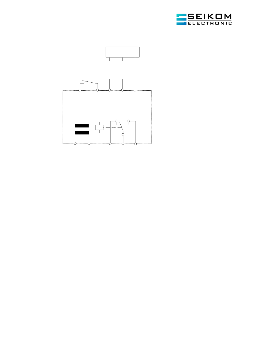
4.2 Electrical Connections
Colors: BN = brown WH = white GN = green YE = yellow
4.3 Setting the Switching Point
The interrelation between air speed and resistance change of the precision resistors is not linear. In
the lower range (low rates of flow) the relative change of resistance is large. In the upper range, the
change of resistance at identical deviations in flow speed becomes increasingly smaller. When setting
the switching point, it must first be determined what change is to be monitored, since some settings
result in certain disadvantages. The following requirements must be taken into consideration:
Low change in the rate of flow in the high flow speed range: the switching point must be chosen
very close to the measuring value of the normal flow, since the change of measuring values is very
small when the rate of flow changes. Since the temperature compensation exhibits a certain amount
of delay in comparison to the actual change of temperature, such a setting of the switching point is
possible only with slow changes of temperature.
Low change in the rate of flow in the low flow speed range: the switching point may be selected at
a greater distance from the measuring value of the normal rate of flow, since the changes of the
measuring values are larger when the rate of flow changes. A change in temperature has no effect on
the switching behaviour.
Large change in the rate of flow: in most cases like this a simple yes/no statement is desired (e. g.
ventilator is running or ventilator stopped). Therefore, a larger safety margin may be selected, so that
neither temperature changes nor turbulence have any influence on the switching behaviour.
The switching points are set on the evaluation unit of the Flow monitor.
16 15 18
BN BK BU
a2 b2 a3
L(+) N(-)
NLSW45-3
Sensor
Z Z a2 b2 a3
Start
t2-60s
BN BK GY
1 2 3

User Manual
NLSW®45-3
Page 8
+49 2058 916 900 0 •info@seikom-electronic.com •www.seikom-electronic.com
4.4 Commissioning Instructions
When commissioning and adjusting the device, the following procedure is recommended:
▪Install and connect the flow controller in accordance with installation instructions and
conditions.
▪Align the mark on the end of the sensor with the air stream.
▪If necessary. Set jumper for start-up delay.
▪Set trimmer “Sensitivity” to minimum sensitivity (left limit stop).
▪Connect main voltage. The green LED lights up. When the jumper is set, the start-up delay
expires (approx. 5... 60 sec.).
▪The yellow LED lights up briefly and goes out again (with maximum set start-up delay, it
remains on until the delay time has elapsed. (If terminal Z/Z* is connected, the relay is
switched through, the yellow LED lights up and the set delay time only expires after the Z/Z
connection is opened).
▪Set nominal rate of flow.
▪Slowly turn trimmer “sensitivity” clockwise until the yellow LED lights up and the signal
output switches. To avoid faulty switching when the flow rate changes slightly, turn the
potentiometer slightly beyond the switching point. If the start-up delay is preset, do not make
this adjustment until the yellow LED has gone out.
▪To check the function of the flow controller, reduce or stop the flow.
▪The yellow LED will go off (output relay at NLSW®45-3 is released).
The device is now set to function.
*Function of terminals Z/Z: Time-delayed start of start-up delay: when terminals Z/Z are bridged, the
relay is switched through / selected start-up delay time expires after the Z/Z connection is opened.
5. MAINTENANCE INSTRUCTIONS
The flow sensor should be serviced at regular intervals, i.e., the flow sensor should be cleaned when
used in heavily contaminated media. The following procedure is expedient:
▪Dismantle flow monitor.
▪Carefully soak the flow monitor in lukewarm soapy water for approx. 10minutes (depending
on the degree of soiling).
▪Carefully rinse the flow monitor with lukewarm water.
▪Install the flow monitor.
▪Put the flow monitor into operation and, if necessary, carry out a new calibration with the
evaluation electronics.
Do not clean the sensor tip with a screwdriver, wire brush or similar. There is a high
risk of damage.

User Manual
NLSW®45-3
Page 9
+49 2058 916 900 0 •info@seikom-electronic.com •www.seikom-electronic.com
6. ERROR MESSAGES
The following instructions are intended as first level support in case your flow monitor is not working
properly.
Problem
Potential Cause
Solution
Device does not work at all.
Missing or wrong supply
voltage.
Check supply voltage and
connection.
Device does not detect a flow.
Sensor is not installed
properly.
Flow is outside of the
measurement range.
Review if the sensor was
installed with its marking
positioned towards the airflow
source and close to the duct’s
center.
Adjust the tube’s diameter to
increase or decrease the flow.
Device detects flow when no
flow is present.
Flow is present even at
standstill e.g., due to
ventilation flaps through
which air enters from the
outside.
Adjust the sensor’s switching
point.
Device shows delayed
reaction behavior.
Sensor tip is polluted.
Carefully clean the sensor
with water.
Device switches in the event
of a rapid media temperature
increase.
Temperature gradient is
outside of technical
specifications.
Turn the "Sensitivity"
potentiometer a little further
clockwise.
Set switching point in hot
media environment.
User Manual
NLSW®45-3
Page 10
+49 2058 916 900 0 •info@seikom-electronic.com •www.seikom-electronic.com
7. EU DECLARATION OF CONFORMITY

User Manual
NLSW®45-3
Page 11
+49 2058 916 900 0 •info@seikom-electronic.com •www.seikom-electronic.com

Growing network of local distributors available online
www.seikom-electronic.com
Our Product Portfolio
Flow
Temperature
Pressure
Air Quality and CO2
Zener Barriers
Universal Transmitters
+49 2058 916 900 0
info@seikom-electronic.com
www.seikom-electronic.com
SEIKOM-Electronic GmbH & Co. KG
Gold-Zack-Straße 7
40822 Mettmann
This manual suits for next models
2
Table of contents


