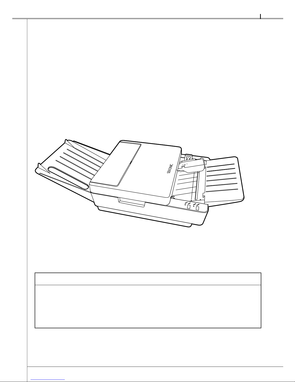
Sekonic SR-1800 User manual

OPTICAL MARK READER
OPERATING MANUAL
SR-1800

SR-1800
1
Introduction
Thank you very much for purchasing our product.
Please read the operating manual before using this product, and be sure to use it properly.
After reading this operating manual, be sure to keep it in a place that you can access at any
time.
NOTICES
1. A part or all of contents of this manual may not be reproduced in any form without the
prior written permission of the publisher.
2. The contents of this manual are subject to change without notice.
3. If you have any doubt or question about the product or the contents of this manual,
please make contact with our sales division or service division.
©2009 SEKONIC Corporation All Rights Reserved.

2
SR-1800
Safety Precautions...................................................................................................................... 4
Warranty ...................................................................................................................................... 7
Precautions for Use .................................................................................................................... 8
Precautions regarding installation..................................................................................... 8
Handling precautions ......................................................................................................... 8
Before Using................................................................................................................................ 9
Before Using the Device..................................................................................................... 9
Unpacking the Device....................................................................................................... 10
Names and Functions of Parts................................................................................................. 11
Main Body Unit.................................................................................................................. 11
Operation Panel ................................................................................................................ 11
Buzzer Sound.................................................................................................................... 13
Preparation for Use................................................................................................................... 14
Attaching the Sheet Feed Tray and Stacker.................................................................... 14
Connecting the AC Adopter ............................................................................................. 15
Installing the USB Driver .................................................................................................. 15
Installing the Diagnostic Utilities ..................................................................................... 15
Connecting the Communication Cable ........................................................................... 16
Connecting to the Computer............................................................................................ 16
Rotary and DIP Switch Settings ...................................................................................... 17
1 Accessing the Rotary and DIP Switches ..................................................................... 17
2 Rotary Switch RSW1 Settings...................................................................................... 17
3 DIP Switch SW1 Settings.............................................................................................. 18
4 DIP Switch SW2 Settings.............................................................................................. 19
5 DIP Switch SW3 Settings.............................................................................................. 21
6 Rotary Switch RSW2 Settings...................................................................................... 22
Inspecting Sheets ..................................................................................................................... 23
Handling and Storing Sheets ................................................................................................... 25
Handling sheets ................................................................................................................ 25
Storage of sheets.............................................................................................................. 25
Marking Instructions................................................................................................................. 26
About Reading Sensitivity Level .............................................................................................. 26
Operation................................................................................................................................... 27
Operation Flow.................................................................................................................. 27
Turning Power On/Off....................................................................................................... 27
1 Turning Power On.......................................................................................................... 27
2 Turning Power Off ......................................................................................................... 27
■
■
■
■
■
■
■
■
■
■
■
■
■
■
■
■
■
■
Table of Contents

SR-1800
3
3 Power Saving Modes .................................................................................................... 28
Setting Sheets................................................................................................................... 29
Reading Sheets................................................................................................................. 32
When an error occurs:...................................................................................................... 32
Checksheet Reading Test ................................................................................................ 32
Troubleshooting ........................................................................................................................ 34
Troubleshooting ................................................................................................................ 34
Error Indicator ................................................................................................................... 35
Fixing Sheet Jams............................................................................................................. 37
Cleaning..................................................................................................................................... 39
Regular Maintenance........................................................................................................ 39
Cleaning Procedures ........................................................................................................ 40
Service Schedule ...................................................................................................................... 42
Product Specifications ............................................................................................................. 43
External Dimensions Diagram.................................................................................................. 44
OMR Glossary ........................................................................................................................... 45
Appendix ...................................................................................................................................... i
Sheet creation reference ..................................................................................................... i
■
■
■
■
■
■
■
■
■

4
SR-1800
Safety Precautions
These “Safety Precautions” pages list various symbols for ensuring safe operation of this product
so as to prevent users or other people from being injured, or property from being damaged.
Read these precautions thoroughly and understand the meanings of the symbols before
proceeding to the main text of this manual.
Warning
Improper operation by neglecting these instructions may result in death or serious injury.
Caution
Improper operation by neglecting these instructions may result in personal injury or
property damage.
Neglecting these instructions may generate smoke or fire.
Neglecting these instructions may cause electric shock.
Indicates a prohibited action.
Indicates that disassembly or modification is prohibited.
Indicates that the power plug must be removed from the outlet for safe
operation.

SR-1800
5
Warning
Fire or electric shock may happen if this product continues to be used when
there is a strange smell or sound.
In such a case, immediately turn the power switch off and then remove the power
plug from the outlet. After making sure that it is no longer smoking, ask the sales
shop for repair service.
Never attempt to repair by yourself since that may be very dangerous.
•
Please do not modify or disassemble this machine. It may result in fire or electric
shock.
Please do not remove the machine´s cover (except for top cover). It may result
in electric shock. Please ask the sales representative internal inspections,
adjustments, and repairs.
Please do not modify or disassemble the included AC adapter. It may result in
fire or electric shock.
•
•
•
Strict care should be taken for the following points.
Otherwise, a fire or electric shock will be caused in some cases.
Cautions to Power Cord
· Do not pull on the cord when drawing the power plug out from the outlet.
· Do not use any power cord other than the specified one.
Cautions to AC adapter
· Do not pull on the cord when drawing the DC plug out from the device.
· Do not use any AC adapter other than the specified one.
Be sure to use the included AC adapter.
Cautions to Device
· Do not use the device with a supply voltage other than the specified one.
· Do not install device in a place that may be wet with water or oil, steam, moisture
or dust.
· Do not insert or drop any metal, foreign combustible matter, etc. into the device
from its opening.
· Do not place containers with chemicals or water, or small metal pieces on or
near the device.
•
•
•
If the device is dropped or the cover is broken, immediately turn the power
switch off and draw the power plug out from the outlet. Then, contact the sales
representative.
•

6
SR-1800
Warning
If any foreign matter should enter inside, immediately turn the power switch off
and remove the power plug from the outlet. Then, contact the sales representative
or Sekonic. If the device continues to be used with foreign matter inside, fire or
electric shock may occur.
If water or other substances penetrate the unit, immediately turn the power
switch off and remove the power plug from the outlet. Then, contact the sales
representative or Sekonic. If the device continues to be used with water or other
foreign matter inside, fire or electric shock may occur.
•
Before moving the device, be sure to remove the power plug from the outlet. If
the cable is damaged, fire or electric shock may occur.
•
Do not connect or disconnect the power plug if your hands are wet. Otherwise,
an electric shock may occur.
•
Caution
Do not place the device in an unstable location. Otherwise, it may fall or collapse,
resulting in injury.
•
When opening or closing the upper part of the main body, do not place your
hand on the sheet-feeding surface. Otherwise, fingers may be caught, resulting
in injury.
If you must touch the sheet-feeding surface of the main body, be careful not to
allow your fingers to be caught or hit.
•
•
When doing maintenance on the device, for your own safety, be sure to remove
the power plug from the outlet.
When the device is not in use for long periods, for safety, remove the power plug
from the outlet.
•
•
Do not put heavy things on the device. Otherwise, it may fall or collapse, resulting
in injury.
•

SR-1800
7
Warranty
The cost-free warranty period for this product extends for one year after delivery.
The company will repair malfunctions arising during this period free of charge if they are
determined to be the company's responsibility. In the event repairs are necessary, as a general
rule the company will keep the product temporarily to carry out such repair work.
Problems arising after the warranty period has expired, problems not covered by the warranty
even if the warranty period has not expired, problems that do not have the seal of the retailer,
malfunctions and other failures caused by customer misuse or by wear and tear of parts due to
repeated use will not be covered by the warranty.
This warranty covers only this product and included accessories, and the company does not
assume any responsibility for monetary damages, lost profits or any claims from third parties
resulting from the use of this device.

8
SR-1800
Precautions for Use
Handle the device with the following points in mind to enable full use of its functions.
Precautions regarding installation
Do not place the device in the following places. Otherwise, failures could result such as sheet
jams, reading errors, or the unit could stop operating.
(1) In direct sunlight or near a heating device.
(2) Outdoors where the main body may not perform satisfactorily due to rain or strong wind.
(3) Places where the machine may not perform satisfactorily, such as unstable or inclined
surfaces, or other locations where the machine may shake while it is operating.
(4) Places subject to sudden temperature changes, excessive moisture and dust.
Recommended temperature: 10 - 30°C (50°F - 86°F)
Guaranteed operating temperature range: 5 - 35°C (41°F - 95°F)
Humidity: 30-80% (no condensation)
Avoid environments outside the above ranges as much as possible.
Handling precautions
(1) Do not connect or disconnect the power plug or DC plug of AC adapter when the device is
in operation or the power switch is on.
(2) Do not move the device while it is operating. Also, do not touch, pull, or push the sheet.
(3) Do not put objects on the device, or sit or lean on it.
(4) Do not give the device a strong vibration and shock etc.
(5) Allow an interval of at least 5 seconds between turning the power switch on and off.
(6) Do not insert foreign objects other than the sheet.
(7) Do not apply force that deforms the sheet while it is being loaded.
(8) Since the sheet reader is equipped with an optical lens, never insert a screwdriver or other
such objects. (Otherwise, reading may be disabled.)
If sheet feeding is disabled due to dust or the like in the sheet feeder, open the top cover to
remove it. See “Cleaning” (P.39).
(9) If the roller becomes soiled with powder from sheets or pencil lead, the roller and the sheet
may slip. In order to prevent slippage, clean the roller at proper intervals. See "Cleaning"
(P.39).
(10) If the exterior of the device is soiled, lightly wipe with a soft cloth wetted with water or a
neutral detergent. Note that wiping with a cloth wetted with volatile chemicals like benzene
or paint thinner may cause deformation or discoloring.
(11) Do not place excessive load on the sheet feed tray and stacker. Doing so may result in
deformation or damage.
(12) When the machine is not used for a prolonged period of time, remove the power cord from
the outlet.
(13) When the machine is not used for a prolonged period of time, keep the hopper set in the
down position.

SR-1800
9
Before Using
Before Using the Device
Before using the device, check if all of the following items are included in the package. If parts
are missing or damaged, contact the store where you purchased the device.
Note
The package does not include a RS-232C interface cable. You are requested to purchase
one depending on your computer port or connection method in the market.
* RS-232C Specifications on OMR side: 9 pin straight cable
1. Main body unit
4. Power cord
For U.S.A
6. Quick guide
8. CD-ROM 9. USB cable
7. A4 checksheets (5 sheets)
Checksheet:
Use it for checking OMR operations.
For Europe
5. AC adapter
2. Stacker 3. Sheet feed tray1. Main body unit
4. Power cord
For U.S.A
6. Quick guide
8. CD-ROM 9. USB cable
7. A4 checksheets (5 sheets)
Checksheet:
Use it for checking OMR operations.
For Europe
5. AC adapter
2. Stacker 3. Sheet feed tray

10
SR-1800
Unpacking the Device
The following parts are fixed with tape to prevent damage in shipping
(1) The device is fixed with tapes. Remove the tapes 1. (5 places)
Also, remove the drying agent (1) and the hopper fixing material (1) from the main body
unit.
(2) Hold Part A of the top cover and open it, pull upward and remove it.
(3) Remove the tape 2from the main body unit. (2 places)
(4) Reattach the top cover.
1
1
1
1
Part A
Top cover
2
Part A
Top cover
2

SR-1800
11
Names and Functions of Parts
Main Body Unit
Number Name Explanation
1 Operation panel Refer to “Operation Panel” below.
2 Hopper Part for loading sheet.
3 Sheet feed tray Tray for sheet supply. (removable)
4 Lock lever Adjusts width to match the sheet width.
5 Lock lever
Lock lever for the hopper. When setting sheets, push this lever to lower the hopper.
After setting sheets, push the lock lever release claw of the lock lever to unlock.
The hopper will return to the sheet supply position.
6 Top cover Remove when cleaning the reader or rollers, and when removing the sheet after a
sheet jam has occurred.
7 Stacker Tray for discharged sheets. (removable)
Operation Panel
Number Name Explanation
8START switch
When pressed once, one sheet is sent through.
When pressed continuously, each sheet is sent through repeatedly.
9
READY lamp(green)
Lights up when the power is on. Indicates that the device is able to communicate
with the computer.
10 CLEAR switch Clears errors. When pressed, the ERROR lamp turns off.
11 ERROR lamp(red) Lights up during the self-check after the power is turned on, and turns off when the
check is complete. Lights up or blinks when an error occurs.
1
2
3
4
65
7
Front
Rear
1
2
3
4
65
7
Front
Rear
891011 891011

12
SR-1800
Number Name Explanation
12 USB connector Port for communication via USB cable.
13
RS-232C connector
Port for communication via RS-232C.
14 DC jack DC plug (AC adapter) connection terminal.
15 Power switch Turns the device ON/OFF.
16 DIP Switch cover Cover for the DIP switch. Bend the cover to remove it.
17
DIP/Rotary switches
Switches for setting device specifications. Before using the device, the switches
must be set.
(Reference: “Rotary and DIP Switch Settings” (P.17))
12 13 14
15
16
17
Front
Rear
12 13 14
15
16
17
Front
Rear

SR-1800
13
Buzzer Sound
This device has a built-in buzzer that indicates operating conditions and errors.
Buzzer Sound Meaning Explanation
Pip!
Confirmation
When the power is on, the buzzer sounds after the self-check is completed
normally.
(Sounds at the same time the ERROR lamp turns off.)
Sounds when the START switch is pressed and one sheet is loaded.
Sounds when the CLEAR switch is pressed and the ERROR lamp turns off.
Pip! Pip! Pip! Caution
Sounds when no sheet is in the hopper and the START switch is
pressed.
Sounds when an abnormality occurs during the checksheet reading test.
Peep! Peep! Peep!
Error Sounds when an error occurs .
ON
OFF
50 ms
ON
OFF
ON
OFF
200 ms 50 ms
50 ms 100 ms
Pip!
Pip! Pip! Pip!
Peep! Peep! Peep!
ON
OFF
50 ms
ON
OFF
ON
OFF
200 ms 50 ms
50 ms 100 ms
Pip!
Pip! Pip! Pip!
Peep! Peep! Peep!

14
SR-1800
Preparation for Use
Prepare the device for use by following the procedure below.
Reference: For information on unpacking the device, refer to “ Unpacking the Device” (P.10).
Attaching the Sheet Feed Tray and Stacker
Attach the sheet feed tray and stacker to the main body unit as shown in the diagrams below.
(1) Attach the sheet feed tray to the side of the main body unit where the sheet is fed.
Insert the hooks (2) of the sheet feed tray into the corresponding holes on the main body
unit.
(2) Attach the stacker to the side of the main body unit where the sheet is discharged.
Hook the hooks (2) of the stacker into the corresponding holes on the main body unit.
Sheet feed traySheet feed tray
StackerStacker

SR-1800
15
Connecting the AC Adopter
Attach the AC adapter (included) to the device.
Be sure to use the included AC adapter, otherwise a fire may result.•
WARNING
(1) Insert the DC plug of the AC adapter into the main body unit's DC jack
(2) Connect the power cord to the AC adapter and the outlet.
Installing the USB Driver
Install the driver on the included CD-ROM.
· For details on how to install the driver, refer to ¥Driver¥Install.txt in the CD-ROM.
Installing the Diagnostic Utilities
Install the diagnostic utilities on the included CD-ROM.
· For details on how to install and use the diagnostic utilities, refer to ¥Diagonistic Utility
¥setup.exe in the CD-ROM.
AC adapter Power cord
DC plug
AC adapter Power cord
DC plug

16
SR-1800
Connecting the Communication Cable
Connect the USB cable (included) or RS-232C interface cable.
(1) Connect the USB cable to the USB connector.
If the RS-232C port is used, connect the RS-232C interface cable to the RS-232C
connector.
CAUTION
· Only either port (USB or RS-232C) can be used.
· An RS-232C interface cable is not provided with the product. Find one that matches your
computer.
· If the RS-232C port is used, the rotary switch and DIP switch must be set properly.
(Reference:“ Rotary and DIP Switch Settings” (P.17))
Connecting to the Computer
This device is equipped with USB and RS-232C interfaces. If the OMR is newly installed, it
is recommended that you connect to USB interface in order for the device to obtain the best
performance. In such a case, use the USB driver on the included CD-ROM.
When this device is replaced with an OMR SR-600 series device, this device can simply be used
by using the RS-232C interface. *1
If RS-232C is used, make sure the communications settings for the device and the computer
are the same. Set the computer's communications settings after referring to the computer or
software user's manual.
*1: Depending on the environment/system used, it may not function properly.
Configure the device's communications settings via the following:
· Switch the USB and RS-232C interfaces
Adjust settings using the DIP switch (SW3-1 and -2). (Reference: “5 DIP Switch SW3
Settings” (P.21))
* For details on the SR-1800 mode commands, refer to the “OMR Command Reference
Manual” and “API Reference Manual for Windows” on the included CD-ROM.
* For details on the SR-600 mode commands, refer to the SR-600 Series Operation
Manual.
USB cable
(RS-232C interface cable)
USB cable
(RS-232C interface cable)

SR-1800
17
Rotary and DIP Switch Settings
The device is shipped from the factory with default settings. Configure the number of lines to
read and device function settings according to its intended use.
If the RS-232C port is used, configure the communication speed and data format settings.
1Accessing the Rotary and DIP Switches
(1) Remove the stacker from the main body unit.
(2) Bend and remove the DIP switch cover on the bottom left of the stacker side.
(Reattach it after set up is complete.)
2Rotary Switch RSW1 Settings
Set the communication speed of the RS-232C port.
CAUTION
· Be careful when configuring settings. Communication errors will occur if settings are
incorrect.
· Make sure the power is off when configuring settings.
: Indicates the factory settings.
SW No. Baud rate [bps]
0 9,600
1 19,200
2 38,400
3 57,600
4 115,200
5 to 9 (Not used)
RSW1 SW1 SW2 SW3 RSW2
DIP switch cover
RSW1 SW1 SW2 SW3 RSW2
DIP switch cover

18
SR-1800
3DIP Switch SW1 Settings
Configure RS-232C port communication format and other settings.
CAUTION
· Be careful when configuring settings. Communication errors will occur if settings are
incorrect.
· Make sure the power is off when configuring settings.
· DIP switch 1-6 (SW1-6) is the back side reader setting, unrelated to the RS-232C settings.
It is set to ON for double-sided specification. Meanwhile, it is set to OFF for single-sided
specification.
: Indicates the factory settings.
No. Contents of setting ON/OFF Explanation
1 Character bit length ON 8
OFF 7
2 Parity ON Absent (Non )
OFF Present (Valid)
3 Parity ON Odd
OFF Even.
4 Stop bit length ON 1
OFF 2
5
Code acceptance status
ON All codes are accepted.
OFF (See Note. 1)
6 Back side reading ON For double-sided specification
OFF For single-sided specification
7 Flow control ON Enabled
OFF Disabled
8 Flow control ON RS/CS
OFF Xon-Xoff
Note 1: According to the setting of “Code Acceptance Status,” it is possible to ignore the
ASCII codes below when processing commands and data received by the device.
Depending on the computers that are connected and programs used, it may be
necessary to configure this setting.
Codes ignored: 20H, 0AH, 7FH, 1AH
NO.
OFF
ON
NO.
OFF
ON

SR-1800
19
4DIP Switch SW2 Settings
CAUTION
· Be careful when configuring settings. Marks will be misread if the settings are incorrect.
· Make sure the power is off when configuring settings.
: Indicates the factory settings.
Contents of setting SW2
No. of lines Timing type 1 2 3 4 5 6 7 8
12 lines
Control type ON ON ON OFF
Direct-under type OFF OFF OFF ON
Mark-to-mark type OFF OFF ON ON
24 lines
Control type OFF OFF ON OFF
Direct-under type ON OFF ON OFF
Mark-to-mark type ON ON OFF OFF
32 lines
Control type OFF ON OFF OFF
Direct-under type ON ON OFF ON
Mark-to-mark type OFF ON OFF ON
38 lines Control type OFF ON ON ON
Direct-under type ON ON ON ON
40 lines
Control type OFF OFF OFF OFF
Mark-to-mark type ON OFF OFF OFF
Direct-under type ON OFF OFF ON
48 lines Direct-under type ON OFF ON ON
Automatic sheet discharge ON ON
OFF OFF
Sheet empty detection ON ON
OFF OFF
Timing mark error detection ON ON
OFF OFF
(Not used) -ON
- OFF
SW2-1 to 4: Select the number of lines to read and the timing mark type according
to the sheet used. Mark-to-mark type is set for “Without top-end margin
reading.”(Reference: “OMR Glossary” (P.45) - Timing control type, Direct under
type, Mark to mark type)
Priority is given to the settings from the computer side.
NO.
OFF
ON
NO.
OFF
ON
This manual suits for next models
1
Table of contents
Other Sekonic Scanner manuals