Selec GTI Series User manual

Creating Best Value
SOLAR GRID TIE INVERTER
(GTI - SERIES)
OPERATING INSTRUCTIONS
Selec Subsidiaries: www.selecusa.com | www.selec-europe.com | www.selecaustralia.comSelec USA: Selec GmbH: Selec Australia:
Selec Controls Pvt. Ltd.
EL-27/1 EL-27/1 PT, EL-27/2 EL-27/3,Electronic Zone, TTC Industrial Area, MIDC Mahape Nai Mumbai,
Raigad, Maharashtra, 400710
Tel.:+91-22-4141 8468 / 452. Fax: +91-22-41418 408. Email: [email protected] | www.selec.com
User Manual
INVERTER GTI -SERIES
26
www.selec.com
General Data
Dimensions (W/H/D) in mm
Weight
500 x 500 x 200
26 kg
-25°C to +60°C
< 3000 m
Operating temperature range
Noise emission (typical)
Altitude
Self consumption at night
500 x 500 x 200
22 kg
-25°C to +60°C
< 3000 m
Natural Convection
Topology
Cooling concept
Environment Protection Rating
Transformer less Transformer less
Natural Convection
IP65 IP65
100.00%
Relative humidity
Features
100.00%
Screw Terminal
DC connection
AC connection
Display
MC4
LCD (16 *2)
Yes
Interfaces: RS485
MC4
Screw Terminal
LCD (16 *2)
Yes
Warranty 5 years
IS 16221-1 /-2,
IS16169
Certificate and approvals IS 16221-1 /-2,
IS16169
5 years
Table 10
< 1W < 1W
AC Terminal
AC Terminal & RS-485 cover screw
RS-485 screw
Enclosure top cover screw
Earthing screw
Ethernet / Wifi cover screw
0.6 Nm
0.7 Nm
0.7 Nm
0.7 Nm
2 Nm
0.7 Nm
10.1 Tightening Torque Required
Table 11
< 30 dB < 30 dB
Internal II, External III
Pollution degree Internal II, External III
AC output III, DC input II
Over voltage category AC output III, DC input II
Class 1, Metal enclosure with
protective earth
Safety class Class 1, Metal enclosure with
protective earth
Outdoor, wet location
Environmental category Outdoor, wet location
Name
GPRS
WiFi
10.2 Spare parts and accessories
Table 12
In the following table you will find the optional accessories for your product. If required you can
order these from Selec Controls Pvt. Ltd.
Description Selec Order no.
Communication interface
Communication interface
GTI006WLM3PW
GTI010WLM3PW
GTI010WLM3PG
GTI006WLM3PG
Version 1.1 | Nov | 2021

6.2 AC connections 11
6.3 Communication module 13
5.2 Installation of inverter 7
9. Decommissioning of inverter 24
7.1 Initial turn on of inverter 23
10.1 Tightening torque required 26
10.2 Spare parts and Accessories 26
7. Commissioning of inverter 23
6. Electrical connections 10
8. Maintenance and cleaning 23
5.1 Safety note before installation 6
6.4 Troubleshooting 20
8.1 Maintenance 23
6.1 DC connection to inverter 10
10. Technical Specification 25
8.2 Cleaning 24
2.5 Symbols on the inverter 4
1.3 Storage of the manual 1
1.2 Target group 1
2.4 Type label 3
2. Product Overview 2
2.7 Storage 4
3.1 Safety during assembly 5
1. Manual Overview 1
1.1 What is inside the manual 1
2.2 Inverter overview 2
1.4 Additional information 1
2.1 Intended use of inverter 2
2.3 Weight and dimensions 3
2.6 Transportation 4
4. Unpacking and accessories 5
3. Safety instructions 5
4.1 Unpacking 5
4.2 Accessories 5
5. Installation 6
INDEX Page No.
25 www.selec.com
10. Technical specifications
Model
Input Data
Max. DC Power 12500W 7500W
Max. DC Voltage 1000Vdc 1000Vdc
Start Up Voltage 180Vdc
180Vdc
PV Voltage Range 160V-1000 Vdc 160V-1000 Vdc
MPP Voltage Range / DC Nominal Voltage 160-1000/630 160-1000/630
Max. PV Isc 16A 16A
Max. Input Current 2 * 11.6A 2 * 11.6A
Backfeed Current 0 A
Number of independent MPP trackers/ strings
per MPP tracker 2/1 2/1
0 A
Output (AC)
Rated AC Output Power 10kVA 6kVA
Max. AC apparent Power 11 kVA 6.6 kVA
Max.Output Current 16A*3 10 A*3
Nominal AC current 13.9*3A 8.33*3A
Nominal AC Voltage 3P/4W/PE,240/415V/50Hz 3P/4W/PE,240/415V/50Hz
Nominal AC Voltage range 320V - 480V 320V - 480V
AC grid frequency 50Hz 50Hz
AC grid frequency range 45Hz - 55Hz 45Hz - 55Hz
Power Factor at rated Power >0.99 >0.99
Adjustable displacement Power Factor 0.8leading-
0.8 lagging
0.8leading-
0.8 lagging
THDi @ Full load & THDv < 2 % < 2 %
AC grid connection type 3 phase + N +E 3 phase + N +E
Efficiency
Max. Efficiency 98.30%
MPPT Efficiency
Protection Devices
DC reverse polarity protection
DC switch for each MPPT
98.30%
>99.5% >99.5%
Yes
Output AC overcurrent protection
Output AC overvoltage protection
Output AC overvoltage protection -Varistor
Integrated all-pole senstive leakage current
monitoring unit
Yes
Yes Yes
Yes Yes
Yes Yes
Yes Yes
Yes Yes
User Manual
INVERTER GTI -SERIES
GTI10kW GTI06kW
Inrush Current <12A /1.6mS <12A /1.6mS
Maximum output fault current 60A/100us 50A/100us
Maximum output overcurrent protection (RMS) 23.3A 23.3A

1
• Please refer to www.selec.com for the updated version of manual
1. Manual Overview
• Selec Controls Pvt. Ltd. holds the rights to make future changes in this manual and accepts no
responsibility to inform the users.
• All the important safety and operational guidelines are present in this manual.
1.2 Target Group
• The content in this manual is meant for qualified persons only.
WARNING
• This manual contains all the technical information required for the installation, operation,
maintenance and troubleshooting of the GTI-SERIES solar inverter.
1.1 What is inside the manual ?
• For safety reasons only a qualified person can install, operate, troubleshoot and repair this device.
NOTE
• To ensure correct and safe operation read this manual properly.
1.3 Storage of the manual
• Keep this manual at a location from where it is accessible all time in case of any emergency.
• Hereby qualified person means one who has received training or has demonstrated skills and
knowledge in construction and in operation of this device.
• Before using GTI-SERIES inverter, please read all safety and operational instructions and warnings
on the unit and in this manual carefully.
• Selec Controls Pvt. Ltd. is not liable for any damages caused by failure to observe and follow these
instructions in the manual.
• Qualified person should also be familiar with local requirements, rules and regulations.
1.4 Additional Information
www.selec.com
NOTICE
• Once a year, turn the rotary switch of the DC disconnect switch from the “ON” position to the
“OFF” position 5 times in succession. This cleans the contacts of the rotary switch and prolongs
the electrical endurance of the DC switch.
8.2 Cleaning
WARNING
• Before starting cleaning of inverter, please ensure that DC switch is turned off and the AC
breaker present between GTI-SERIES inverter and grid is also turned off. After switching off
the DC switch and AC breaker wait for atleast 5 minutes to avoid risk of electric shock.
CAUTION
• Risk of burns due to hot heatsink.
0
• The heatsink may exceed 70 C during operation. Do not touch the heat sink during operation.
Wait atleast 30 minutes before cleaning until the heat sink has cooled down.
• Do not use water, corrosive chemicals or detergent to clean inverter and heatsink.
• Please clean the inverter with an air blower, a dry & soft cloth or a soft brush.
• Please ensure that there is enough space around the heatsink for ventilation. Inspect the heat
sink for blockage (dust, snow, etc.) and clean them if they exist using an air blower, a dry and
soft cloth.
• Turn OFF AC breaker.
9. Decommissioning of inverter
• Turn OFF DC switch.
• Remove DC cables
• Remove AC cables.
• Unscrew mounting screws to remove inverter from wall.
• Adopt E-waste Regulation guideline while disposing faulty inverter. Do not dispose inverter with
household waste.
• Wait till i) Alarm LED turn OFF ii) LCD light turn off.
• Remove Rs-485, Dry contact DI terminal connection if you have done any.
• Unscrew Communication plate.
• Wait for approx. 30 minutes before touching Inverter. Surface may be hot.
• Pack inverter in carton which is provided during purchase.If that carton is not available then
use equal size carton.
• Unscrew AC Connector.
• Unlock Communication gland.
24
www.selec.com
User Manual
INVERTER GTI -SERIES
User Manual
INVERTER GTI -SERIES

2
2.1 Intended use of inverter
GTI-SERIES inverter are Grid Tied Solar Inverter. When sunrays fall upon the PV array, DC power is
generated by these arrays. This power is fed to the inverter as input. Inverter will convert this DC power
into AC power and feed it to three phase utility grid. GTI-SERIES are two string inverter with two
independent MPPT trackers.
Overview of complete Grid Tied PV system with GTI-SERIES inverter :
2. Product Overview
As shown in Fig 1, the complete system consists of PV array, DC distribution box, GTI-SERIES
inverter, AC distribution box and utility grid.
www.selec.com
2.2 Inverter Overview
4) AC output 8) Type label
3) Communication port 7) DB9 RS485
1) Input PV terminals 5) Protective earth terminal
2) DC switch 6) LCD
1
2
4
35
6
7
Fig 2
8
Fig 1
PV STRING2
PV STRING 1
UTILITY GRID
DC
DISTRIBUTION
BOX
AC
DISTRIBUTION
BOX
SURGE ARRESTOR
DC BREAKER
FUSE
SURGE ARRESTOR
AC BREAKER
INVERTER
23 www.selec.com
1ADC Sensing Err-PV1 PV1 Current Sensing Error
2
3
4
5
6
7
8
ADC Sensing Err-PV2
ADC Sensing Err-L1
ADC Sensing Err-L2
ADC Sensing Err-L3
ADC Sensing Err-BNTC
ADC Sensing Err-INTC
ADC Sensing Err-CNTC
PV2 Current Sensing Error
Inverter L1-Phase Current Sensing Error
Inverter L2-Phase Current Sensing Error
Inverter L3-Phase Current Sensing Error
Boost Module NTC Sensing Error
Inverter Module NTC Sensing Error
Main Controller NTC Sensing Error
1.Restart Inverter, if error persists contact
Selec Controls Pvt Ltd.
7. Commissioning of inverter
Caution
• Check AC & DC Voltages are within range of particular GTI-SERIES inverter specification.
• Check protective earth is connected.
• Check DC connectors are connected.
• Check AC connectors are Connected.
7.1 Initial turn on of inverter
• Turn ON DC switch . As soon as DC switch is ON , LCD display will glow. There are two LED
indications on front sticker. Red is alram & Green is Grid feed status.
• Inverter starts self test, for checking internal circuitary is proper or not before doing grid feed.
• If any fault occurs, then alarm LED will glow in red colour this will alert user regarding a particular fault.
• If every thing is normal then, inverter starts feeding power into the grid . Grid status LED will
glow green.
Table 9
6.4.d) ADC Sensing Error Definitions
ADC Sensing Error Definitions
Sr.No Error Message Error Description Suggestion
8. Maintenance and cleaning
8.1 Maintenance
WARNING
• Before any maintenance, please switch AC and DC power off atleast 5 minutes before proceeding to
avoid risk of electrical shock.
• Normally, the inverter needs no maintenance. Check for any external visible damage and discoloration
of the cables and DC switch at regular intervals. Check that all terminals, screws and cables are
connected and appear as they did upon installation. If there is any visible damage or visible
discoloration of cables or DC switch or if there is any impaired
and loose part, please contact the installer.
User Manual
INVERTER GTI -SERIES
User Manual
INVERTER GTI -SERIES

Fig 3(a) Side View
Fig 3(b) Front View
A
B
C
D
C : 500mm D : 200mm
A : 420mm B : 500mm
User Manual
INVERTER GTI -SERIES
2.4 Type label
Type label is present on the right hand side of inverter. Type label has information about
inverter specific characteristics, various symbols, certificates and approval.
2.3 Weight and dimensions
1) Weight of the Inverter is 26 Kilogram.
3www.selec.com
22
www.selec.com
6.4.c) Self Test Error Definitions
Self Test Error Definitions
Sr.No Error Message Error Description Suggestion
Table 8
1COMM ERR
FRC1 ERR
FRC2 ERR
PV LOW ERR
GRID ERR
GRID FREQ ERR
ADC SENSING ERR
EARTH ABS ERR
AC CONN ERR
WRONG GRID ERR
INS RES ERR
OUTPUT RLY1 ERR
2
4
3
5
6
7
8
9
10
11
12
13
Internal Communication Error
PWM FRC connection Error
ADC FRC connection Error
PV low voltage
GRID Absent/Out of Range
GRID Frequency Error
Current/NTC Sensing Error
Earth Absent/ Inverter Earth
to Neutral Voltage Error
Line Neutral Swapped
GRID Voltage Out of Range
Insulation Resistance
Out of Range
Output Relay1 Error
1.Turn OFF DC Switch.
2.Check PV voltage with Multimeter.
3.If voltage is more than 250V,contact Selec Controls Pvt Ltd.
1.Turn OFF DC Switch.
2.Check AC wiring, whether any Line wire is swapped with
Neutral or ground.
3.Check Earthing connection.
4. Restart Inverter, if error persists contact Selec Controls Pvt Ltd.
ENABLE PINS ERR
RCMU CT ERR
MEMORY ERR
14
15
16
Control Enable Pin Error
RCMU CT Detection Error
EEPROM memory log error
1.Restart Inverter, if error persists contact
Selec Controls Pvt Ltd.
1.Turn OFF DC Switch.
2.Check AC Voltage on the inverter terminal.
3.Check AC wiring, whether any Line wire is swapped with
Neutral or ground.
4.Restart Inverter, if error persists contact Selec Controls Pvt Ltd.
1.Turn OFF DC Switch.
2. Restart Inverter, if error persists contact Selec Controls Pvt Ltd.
1.Restart Inverter, if error persists contact Selec Controls Pvt Ltd.
1.Turn OFF DC Switch.
2.Check AC Voltage on the inverter terminal.
3.Check AC wiring, whether any Line wire is swapped with
Neutral or ground.
4.Restart Inverter, if error persists contact Selec Controls Pvt Ltd.
1.Turn OFF DC Switch & Turn off AC supply.
2.Check AC wiring, whether any Line wire is swapped with
Neutral or ground.
3.Check Earthing connection.
4. Restart Inverter, if error persists contact Selec Controls Pvt Ltd.
1.Turn OFF DC Switch & Turn off AC supply.
2.Check Solar PV enclosure earthing.
3.Check earthing of inverter.
4. Restart Inverter, if error persists contact Selec Controls Pvt Ltd.
Output Relay2 Error
OUTPUT RLY2 ERR
1.Restart Inverter, if error persists contact
Selec Controls Pvt Ltd.
PV1 UNSTABLE ERROR
17
PV2 UNSTABLE ERROR
18
PV1 UNSTABLE ERROR
PV2 UNSTABLE ERROR
1.Check PV connection & voltage
2.If PV voltage variation greater than 15V then
check grounding of system
User Manual
INVERTER GTI -SERIES
PV GRID INVERTER
Made In India
------------------------------------------------------
IS16221-1&2
IS16169 IP65
5min
Model : GTI 06kW
Reference ID : GTI006WLM3PW
-----------------------------------------------------
DC Input Range : 160-1000 VDC
Max. DC Voltage : 1000 VDC
MPPT Voltage Range : 160-1000 VDC
Max. Input Current : 2*11.6 A
Isc PV (Absolute maximum)
DC per MPPT : 16A
-----------------------------------------------------
AC Output : 240/415 VAC, 50Hz
3P/4W/PE, cosφ 0.8lag~0.8lead
Max. Output current : 3*10 A
Apparent Power :
6kVA nom, 6.6kVA max
-----------------------------------------------------
Safety Level : Class 1
Ambient Temp : -25°C...+60 C°
-----------------------------------------------------
Mfg. By: Selec Controls Pvt. Ltd.,
EL-27/1 EL-27/1 PT, EL-27/2 EL-27/3,
Electronic Zone, TTC Industrial Area,
MIDC Mahape Nai Mumbai, Raigad,
Maharashtra, 400710
PV GRID INVERTER
Made In India
------------------------------------------------------
IS16221-1&2
IS16169 IP65
5min
Model : GTI 10kW
Reference ID : GTI010WLM3PW
-----------------------------------------------------
DC Input Range : 160-1000 VDC
Max. DC Voltage : 1000 VDC
MPPT Voltage Range : 160-1000 VDC
Max. Input Current : 2*11.6 A
Isc PV (Absolute maximum)
DC per MPPT : 16A
-----------------------------------------------------
AC Output : 240/415 VAC, 50Hz
3P/4W/PE, cosφ 0.8lag~0.8lead
Max. Output current : 3*16 A
Apparent Power :
10kVA nom, 11kVA max
-----------------------------------------------------
Safety Level : Class 1
Ambient Temp : -25°C...+60 C°
-----------------------------------------------------
Mfg. By: Selec Controls Pvt. Ltd.,
EL-27/1 EL-27/1 PT, EL-27/2 EL-27/3,
Electronic Zone, TTC Industrial Area,
MIDC Mahape Nai Mumbai, Raigad,
Maharashtra, 400710
PV GRID INVERTER
Made In India
------------------------------------------------------
IS16221-1&2
IS16169 IP65
5min
Model : GTI 06kW
Reference ID : GTI006WLM3PW
-----------------------------------------------------
DC Input Range : 160-1000 VDC
Max. DC Voltage : 1000 VDC
MPPT Voltage Range : 160-1000 VDC
Max. Input Current : 2*11.6 A
Isc PV (Absolute maximum)
DC per MPPT : 16A
-----------------------------------------------------
AC Output : 240/415 VAC, 50Hz
3P/4W/PE, cosφ 0.8lag~0.8lead
Max. Output current : 3*10 A
Apparent Power :
6kVA nom, 6.6kVA max
-----------------------------------------------------
Safety Level : Class 1
Ambient Temp : -25°C...+60 C°
-----------------------------------------------------
Mfg. By: Selec Controls Pvt. Ltd.,
EL-27-1, Electronic Zone, TTC Ind. Area,
MIDC, Mahape, Navi Mumbai 400710, INDIA.
PV GRID INVERTER
Made In India
------------------------------------------------------
IS16221-1&2
IS16169 IP65
5min
Model : GTI 10kW
Reference ID : GTI010WLM3PW
-----------------------------------------------------
DC Input Range : 160-1000 VDC
Max. DC Voltage : 1000 VDC
MPPT Voltage Range : 160-1000 VDC
Max. Input Current : 2*11.6 A
Isc PV (Absolute maximum)
DC per MPPT : 16A
-----------------------------------------------------
AC Output : 240/415 VAC, 50Hz
3P/4W/PE, cosφ 0.8lag~0.8lead
Max. Output current : 3*16 A
Apparent Power :
10kVA nom, 11kVA max
-----------------------------------------------------
Safety Level : Class 1
Ambient Temp : -25°C...+60 C°
-----------------------------------------------------
Mfg. By: Selec Controls Pvt. Ltd.,
EL-27-1, Electronic Zone, TTC Ind. Area,
MIDC, Mahape, Navi Mumbai 400710, INDIA.

Symbol
5
MIN
IP65
User Manual
INVERTER GTI -SERIES
4
www.selec.com
Read the manual before installing GTI-SERIES Inverters.
Do not dispose this inverter with household waste.
CE mark. The inverter complies with the requirements of applicable EC guidelines.
Protective earth terminal.
GTI-SERIES inverter complies with IP65 norms.
Description
Be careful of high voltages.
Risk of burns due to hot surfaces.
Risk of danger. Failure to observe safety information in manual may result in serious
injury or death.
Table 1
Indications on front side of inverter :
Indication Description
Alarm status.
Status of grid connection.
Red LED
Green LED
Table 2
Residual voltage Hazard. Please wait for 5 minutes before opening to ensure the
capacitors are completely discharged.
2.5 Symbol on the Inverter
Our inverters go out of the factory in proper electrical and mechanical condition after thorough testing and
inspection. To ensure safe and careful transportation special packaging is used. If you find packing
problems or find any visible damage, please immediately contact your dealer or Selec Controls Pvt Ltd.
Transport of the equipment, especially by road, must be carried out with suitable means for protecting the
components, in particular the electronic components from violent shocks, humidity, vibration, etc.
2.7 Storage
While not in load condition, Inverter should be stored in clean, dry and covered space in original packaging.
2.6 Transportation
1.Restart Inverter, if error persists contact
Selec Controls Pvt Ltd.
21
22
23
UNDER VOLTAGE L1
UNDER VOLTAGE L2
UNDER VOLTAGE L3
Inverter L1-Phase Under Voltage
Inverter L2-Phase Under Voltage
Inverter L3-Phase Under Voltage
1.Turn OFF DC Switch.
2.Check AC Voltage on the inverter terminal.
3.Check AC wiring, whether any Line wire is swapped with
Neutral or ground.
4.Restart Inverter, if error persists contact Selec Controls Pvt Ltd.
24
25
26
DC BUS UV
DC BUS OV
DC BUS UB
DC Bus Low Voltage
DC Bus Over Voltage
DC Bus Unbalance
27
28
GRID FREQ OF
GRID FREQ UF
Grid Frequency High
Grid Frequency Low
1.Turn OFF DC Switch.
2.Check AC frequency on the inverter terminal.
3. Restart Inverter, if error persists contact Selec Controls Pvt Ltd.
Table 7
21 www.selec.com
1INS RES
RCMU
COMM
EARTH
CNTR NTC
TEMPERATURE
CNTR
TEMPERATURE
BOOST
TEMPERATURE INV
OVER CURRENT
PV1
OVER CURRENT
PV2
OVER CURRENT L1
OVER CURRENT L3
2
4
3
5
6
7
8
9
10
11
12
1.Turn OFF DC Switch & Turn off AC supply.
2.Check Solar PV enclosure earthing.
3.Check earthing of inverter.
4. Restart Inverter, if error persists contact Selec Controls Pvt Ltd.
Inverter Residual Current
Out of Range
Internal Communication Error
Earth Absent/ Inverter Earth to
Neutral Voltage High
Controller Temperature
Out of Range
Main/Redundant Controller
Temperature Out of Range
Boost Temperature
Out of Range
Inverter Temperature
Out of Range
Boost1/PV1 Over Current
Boost2/PV2 Over Current
Inverter L1-Phase Over Current
Inverter L3-Phase Over Current
OVER VOLTAGE PV1
OVER VOLTAGE PV2
Boost1/PV1 High Voltage
Boost2/PV2 High Voltage
Inverter L2-Phase Over CurrentOVER CURRENT L2
PV Insulation Resistance
Out of Range
Restart Inverter, if error persists contact Selec Controls Pvt Ltd.
Restart Inverter, if error persists contact Selec Controls Pvt Ltd.
1.Turn OFF DC Switch & Turn off AC supply.
2.Check Solar PV enclosure earthing.
3.Check earthing of inverter.
4. Restart Inverter, if error persists contact Selec Controls Pvt Ltd.
1.Check ambient temperature.
2.Check installation enviorment.
3.Restart Inverter, if error persists contact
Selec Controls Pvt Ltd.
1.Restart Inverter, if error persists contact
Selec Controls Pvt Ltd.
1.Turn OFF DC Switch.
2.Check PV voltage with Multimeter
3.If voltage is lower than 1000V,contact Selec Control Pvt Ltd.
13
14
15
OVER VOLTAGE L1
OVER VOLTAGE L2
OVER VOLTAGE L3
Inverter L1-Phase Over Voltage
Inverter L2-Phase Over Voltage
Inverter L3-Phase Over Voltage
1.Turn OFF DC Switch.
2.Check AC Voltage on the inverter terminal.
3.Restart Inverter, if error persists contact
Selec Controls Pvt Ltd.
16
17
UNDER VOLTAGE PV1
UNDER VOLTAGE PV2
Inverter L3-Phase Over Voltage
Boost2/PV2 Low Voltage
1.Turn OFF DC Switch.
2.Check PV voltage with Multimeter.
3.If voltage is more than 200V,contact Selec Controls Pvt Ltd.
6.4.b) Error Definations
Error Definitions
Sr.No Error Message Error Description Suggestion
18
19
20
User Manual
INVERTER GTI -SERIES

User Manual
INVERTER GTI -SERIES
During transportation unpredictable damages may occur with inverter unit and the accessories. On
receiving the unit please do thorough inspection for any visible external damages on package. If any
external visible damage is found, do not unpack inverter unit and contact the dealer as soon as
possible.
Once you unpack the unit, please ensure that all accessories are present in the box and undamaged.
Please contact your dealer if anything is missing or damaged. All the accessories present in the box are
listed as follow in Fig 4 & Table 3.
This chapter contains safety instructions and guidelines that must be followed at all times while working
on or with the product. To prevent personal injury, property damage and to ensure long-term operation
of the product, read this section carefully and observe all safety information at all times.
4.1 Unpacking
4. Unpacking and accessories
3.1 Safety during assembly
• Unintended use of this inverter is sole risk of the operator and manufacturer/supplier is not
responsible for any damage caused by such use.
• For safety reasons only a qualified person can install, operate, troubleshoot and repair this device.
Qualified person should also be familiar with local requirements, rules and regulations.
4.2 Accessories
3. Safety instructions
• The GTI-SERIES inverter should be operated with permanent connection with utility grid and not
recommended for mobile use.
WARNING
5www.selec.com
Fig 4
1
2
MANUAL
567
4
3
4
PV1 OV
PV2 OV
PV1 UV
PV2 UV
PV1 OC
PV2 OC
BUS OV
BUS UB
21
22
23
24
25
26
27
20
BUS UV
28
PV1 High Voltage
PV2 High Voltage
PV1 Low Voltage
PV2 Low Voltage
PV1 Over Current
PV2 Over Current
DC Bus Over Voltage
DC Bus Unbalance
DC Bus Low Voltage
1.Turn OFF DC Switch.
2.Check PV voltage with Multimeter
3.If voltage is lower than 1000V,contact Selec Controls Pvt Ltd.
1.Turn OFF DC Switch.
2.Check PV voltage with Multi meter
3.If voltage is more than 180V,contact Selec Controls Pvt Ltd.
Table 6
1.Restart Inverter, if error persists contact Selec Controls Pvt Ltd.
Log Variables Data
Sr.No Log Code Log Description Suggestion
1.Turn OFF DC Switch.
2.Check AC Voltage on the inverter terminal.
3.Check AC wiring, whether any Line wire is swapped with
Neutral or ground.
4.Restart Inverter, if error persists contact Selec Controls Pvt Ltd.
1OV L1
OV L2
OV L3
UV L1
UV L2
UV L3
2
4
3
5
6
L1-Phase Over Voltage
L2-Phase Over Voltage
L3-Phase Over Voltage
L1-Phase Under Voltage
L2-Phase Under Voltage
L3-Phase Under Voltage
1.Turn OFF DC Switch.
2.Check AC Voltage on the inverter Output terminal.
3.Restart Inverter, if error persists contact
Selec Controls Pvt Ltd.
OC L1
OC L2
OC L3
7
8
9
L1-Phase Over Current
L2-Phase Over Current
L3-Phase Over Currnet
1.Disturbance in AC Voltage.
2.Surge Occurs during operation.
3.Restart Inverter, if error persists contact Selec Controls Pvt Ltd.
FREQ H
11 Grid Frequency High
VEN HIGH
10 Earth Voltage Out of Range
FREQ L
12 Grid Frequency Low
1.Turn OFF DC Switch.
2.Check AC frequency on the inverter terminal.
3.Restart Inverter, if error persists contact Selec Controls Pvt Ltd.
INS RES
13 PV Insulation Resistance
Out of Range
1.Turn OFF DC Switch & Turn off AC supply.
2.Check Solar PV enclosure earthing.
3.Check earthing wire connection of inverter.
4.Restart Inverter,if error persists contact Selec Controls Pvt Ltd.
RCMU
14 Inverter Residual Current
Out of Range
1.Restart Inverter,
if error persists contact Selec Controls Pvt Ltd.
DUTY
15 Inverter Duty Out of Range 1.Restart Inverter,
if error persists contact Selec Controls Pvt Ltd.
1.Turn OFF DC Switch & Turn off AC supply.
2.Check Solar PV enclosure earthing.
3.Check earthing wire connection of inverter.
4.Restart Inverter, if error persists contact Selec Controls Pvt Ltd.
1.Turn OFF DC Switch.
2.Check AC frequency on the inverter terminal.
3.Restart Inverter, if error persists contact Selec Controls Pvt Ltd.
6.4.a) Log Variable Data
6.4 Troubleshooting
INV NTC
BST NTC
RC NTC
16
18
17
19
Main Controller Temperature
Out of Range
Inverter Module Temperature
Out of Range
Boost module Temperature
Out of Range
Redundant Controller Temperature
Out of Range
MC NTC
1.Check ambient temperature.
2.Check installation environment.
3.If error persists contact Selec Controls Pvt Ltd.
20
www.selec.com
User Manual
INVERTER GTI -SERIES

6
www.selec.com
Table 3
Quantity
1
2
3
4
5
6
7
1
1
2
2
2
1
Item
4
Description
Inverter
User Manual
PV male connector
PV female connector
Cable gland for AC and communication output
Earth allen screw with 2 plane & 1 spring washer with lug
Wall mount anchor bolt
5. Installation
5.1 Safety note before installation:
• Weight of GTI-SERIES Inverter is 26 kg. Hold inverter tightly before mounting & moving.
This chapter guide installer how to install GTI-SERIES inverter.
Caution
Warning
• Avoid installing GTI-SERIES inverter near or on flammable materials.
• Hot surface of GTI-SERIES Inverter may create a burn hazard to a person who is touching hot
surface, to avoid this mount inverter at appropriate height.
• Output of inverter is AC (Alternating current) which is connected to a utility grid. Power generated
from inverter is delivered to a utility grid hence it should not be connected any other AC source or
generator.
• Make sure DC switch is at OFF position. If it is on ON position switch it to OFF position.
• Mounting surface should be rigid & able to handle weight of GTI-SERIES inverter.
• Input to this inverter is DC (Direct current) which is a PV array generator. Do not connect any
other source to it.
Fig. 21
c) Monitor Inverter with External wireless device
19 www.selec.com
Fig.19
b) Monitor multiple inverters with RS485
Fig.20
RS485
TO
USB
CONVERTER
ALARM
GRID
RS485
TO
USB
CONVERTER
GTI
ALARM
GRID
GTI
ALARM
GRID
GTI
ALARM
GRID
GTI
ALARM
GRID
GTI
ALARM
GRID
GTI
ALARM
GRID
ALARM
GRID
GTI
ALARM
GRID
GTI
ALARM
GRID
GTI
ALARM
GRID
GTI
ALARM
GRID
ALARM
GRID
GTI
ALARM
GRID
GTI
ALARM
GRID
GTI
ALARM
GRID
GTI
ALARM
GRID
GTI
ALARM
GRID
GTI
ALARM
GRID
GTI
ALARM
GRID
GTI
ALARM
GRID
GTI
ALARM
GRID
ALARM
GRID
6.3.3.2 Monitor inverter status.
a) Monitor single inverter's status with RS485
GTI
ALARM
GRID
GTI
ALARM
GRID
GTI
ALARM
GRID
GTI
ALARM
GRID
ALARM
GRID
GTI
ALARM
GRID
GTI
ALARM
GRID
GTI
ALARM
GRID
GTI
ALARM
GRID
ALARM
GRID
GTI
ALARM
GRID
GTI
ALARM
GRID
GTI
ALARM
GRID
ALARM
GRID
Router
Mobile Phone
WIFI Dongle
Internet
User Manual
INVERTER GTI -SERIES
User Manual
INVERTER GTI -SERIES

GTI-SERIES inverter is developed for use in an outdoor location with IP 65 protection but avoid
direct contact of inverter with sunlight, rainfall and snowfall. Fig 5 shows ideal locations for installation of
inverter.
5.2 Installation of inverter
• Mount the GTI-SERIES inverter on rigid, strong wall in such way that it can handle weight of inverter.
• Mount inverter on such a height that commissioning, decomissioning, turning ON and turning
OFF is easily possible.
NOTICE
INVERTER
AB
C
Fig 5
Ideal installing position shown in fig 6. -
Fig 6
7www.selec.com
TO CHANGE PWD
PRESS ENT
Enter PWD
0000
Enter PWD
0000
Enter PWD
1000
Enter PWD
1100
Enter PWD
1000
Re-ENT PWD
0000
Re-ENT PWD
0000
Re-Enter PWD
1000
Re-ENT PWD
1000
Re-Enter PWD
1100
Password Changed
ENTER KEY
UP KEY
DOWN KEY
UP KEY
DOWN KEY
ENTER KEY
UP KEY
DOWN KEY
UP KEY
ENTER KEY DOWN KEY
NOTE : 1) Press UP key to scroll around digits.
2) Press DOWN key to change digits.
d) TO CHANGE PASSWORD
Pin description of RS-485 Communication terminal is given below in Table 5
6.3.3.1 RS-485 Configuration
6.3.3 Communication module connections
Baud rate : 115200
Parity : N/A
Data bits : 8
Connecting single inverter for RS-485 communication :
• Connect A+ & A- pin of RS-485 port to the Data +, Data -.
Following data format is used for Communication
Data Format:
Stop bit : 2
Pin Notation
A+
A-
Function
Data +
Data -
Table 5
18
www.selec.com
User Manual
INVERTER GTI -SERIES
User Manual
INVERTER GTI -SERIES
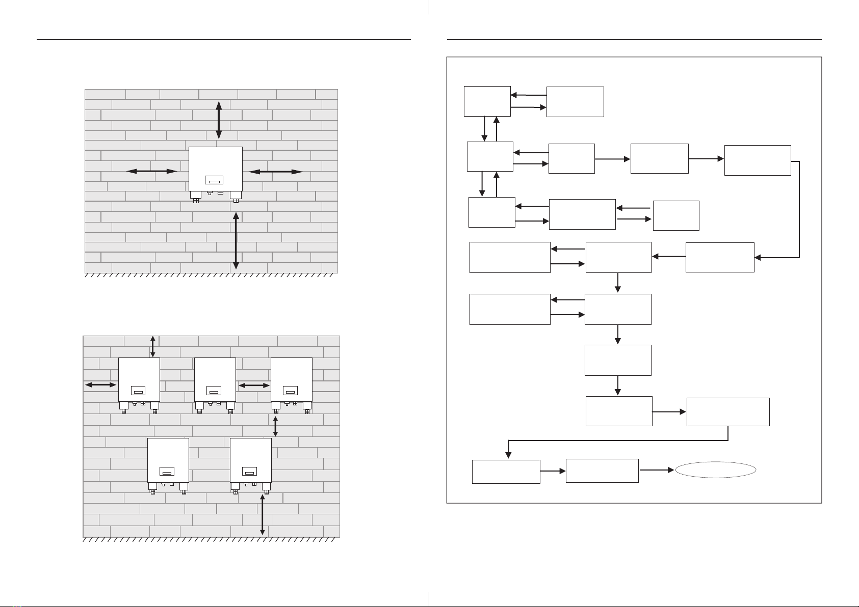
5.2.1 Clearance for installation
Install inverter on wall with minimum clearence as shown in fig 7.
To install more than one inverter in series follow fig 8. for minimum clearance. This clearance should be
provided for easy installation, removal & heat dissipation of GTI-SERIES inverter.
>300mm >300mm
>300mm
>1000mm
>1000mm
>300mm>300mm
>200mm
Fig 7
Fig 8
8
www.selec.com
>300mm
c) LONG PRESS UP KEY
ENT
ESC
ESC
DOWN
UP
ENT
DOWN DOWN
ESC
ENT
DOWN DOWN
ENTER
PASSWORD
ACTIVE POWER
(SET%) 10.00% POWER FACTOR
VAL : 1.00
MAIN DSP ID:1
SW:1 HW:1
RED ID:1
SW:1 HW:1
POWER FACTOR
MODE LEAD
UP KEY
DOWN KEY
ERROR LOG
INVERTER
INFO
SR.NO. DATE
ERR TIME
UP KEY
DOWN KEY
INVERTER
SETTING
Note : 1) Error log will store last 20 errors.
2) Sr. No : Total No. of errors.
3) Date : Date of error occurs.
4) Time : Time at which error occurs
5) Err : Log code will appear ( Refer table No. 6 )
17 www.selec.com
SET VEN VAL IS 0
SELEC INS VAL 0
DRY CONTACT
DISABLE
TO CHANGE PWD
PRESS ENT
DOWN
ENTER PWD
XXXX
RE-ENT PWD
XXXX
ENT ENT
GO TO HOME PAGE
ENT
PRESS ENT TO
SET GRID
VOLT LIMIT
ESC
ENT
LOWER LIMIT 200.0
UPPER LIMIT 280.0
DOWN
PRESS ENT TO
SET GRID
FREQ. LIMIT
ESC
ENT
LOWER LIMIT 48.0
UPPER LIMIT 52.0
DOWN
DOWN
User Manual
INVERTER GTI -SERIES
User Manual
INVERTER GTI -SERIES

Step1 : Drill four holes on wall at distance of inverter mounting position as shown in fig.9 & insert
anchor bolt in holes.
5.2.2 Mounting inverter on wall:
Steps to mount inverter
Step2 : Mount inverter on anchor bolt with help of at least two people. Tighten the nut and ensure
inverter is properly fitted on anchor bolt as per fig 10.
Fig 10
A = 470mm
B = 300mm
Fig 9
9www.selec.com
6.3.2.1 LCD KEY FUNCTIONALITY
NOTE : 1) Press UP key to scroll around digit.
2) Press DOWN key to change digit.
b) TO CHANGE DATE/TIME
a) LONG PRESS ESC KEY
BL Ver : 18.0-1
SCAN : 3mS/sc
DOWN KEY
UP KEY
DOWN KEY UP KEY
UP KEY
ESC
ENT
DOWN
UP
ESC
ENT
1-SYSTEM INFO
2-COM SETTING
3-MODBUS DATA
SLAVE ID : 001
115K 8N1
DATE : 26-01-2021
TIME : 11:46:23
4-DEBUG MODE
DOWN KEY
5- SERIAL NO
1
UP KEY
DOWN KEY
ESC
ENT
SERIAL NO
C2021000A-123
DATE : 16-01-2021
TIME : 11 : 46 : 23 DATE : 16-01-2021
TIME : 11 : 46 : 23
DATE : 26-01-2021
TIME : 11 : 46 : 23
DATE : 16-01-2021
TIME : 11 : 46 : 23
DATE : 16-01-2021
TIME : 11 : 46 : 23
DATE : 16-01-2021
TIME : 21 : 46 : 23
Change Saved
ENTER KEY
DOWN KEY
UP KEY
DOWN KEY
ENTER KEY
ENTER KEY
1
16
www.selec.com
User Manual
INVERTER GTI -SERIES
User Manual
INVERTER GTI -SERIES

2) Make sure PV connector's ( Male & female) polarity is proper.
3) Connect PV connectors as shown in fig.13
4) Make sure connectors to Inverter DC terminal are connected properly.
1) Do not connect PV array positive terminal or negative terminal to the grounding of system.
6.1. DC Connection to inverter :
Caution
Check if DC Disconnect switch is in OFF position as shown in following Fig 11.
6. Electrical connections
This section helps installer, how to do electrical connection to GTI-SERIES inverter. Electrical
connection has to be performed by qualified and authorised person only.
Fig 11
ŸDo not disconnect AC & DC cables under load condition.
ŸEnsure string's open circuit voltage should be less than inverter's maximum input voltage.
Applying more voltage can damage inverter.
Warning
ŸWhenever a PV array is exposed to sunlight it supplies DC Voltage. Shock hazard may occurs if
terminals are open. Cover PV array with opaque material before commencing any wiring.
Model Current Rating Wire Size
11.6A 4 sq.mm
11.6A 4 sq.mm
10
www.selec.com
NOTE:- 1) Error will be visible on screen when they occur. (Refer table no. 7 for Error Definition).
2) When system is on & any self test error occurs screen will jump to self testing page.
3) Use Esc key to go on Home page.
6.3.2 LCD Flow Chart
GRID IS
PRESENT
GRID CONNECT
TM IS ZERO
PRESS ENT KEY THEN DOWN KEY
LONG PRESS
ENT KEY
UP KEY
DOWN KEY
UP KEY
ENT
ESC
UP KEY
DOWN KEY
DOWN KEY
UP KEY
DOWN KEY
UP KEY
DOWN KEY
UP KEY
DOWN KEY
DOWN KEY UP KEY
DOWN KEY UP KEY
DOWN KEY UP KEY
DOWN KEY UP KEY
DOWN KEY UP KEY
DOWN KEY UP KEY
PV1 PWR: 0.0W
PV2 PWR: 0.0W
ADC Sen ERR
INV STATUS : OFF
PHASE SEQ : CW
UP KEY
DOWN KEY
DOWN KEY
UP KEY
ERROR
DOWN KEY
UP KEY
GTI 10KW
SELF TESTING...
COMM ERR
GRID CONNECT TM
45
E-DAY : 3.2kwh
E-TOTAL : 100kwh
PV1 0.0V 0.0A
PV2 0.0V 0.0A
L1 0.0V 0.0A
L2 0.0V 0.0A
L3 0.0V 0.0A
GRID FREQ 0.0Hz
ACTV PWR 0.0 W
REAC PWR 0.0 W
APPR PWR 0.0 W
FREQ ERROR
DC LINK
TEMPERATURE
UNDER VOLTAGE
OVER VOLTAGE
OVER CURRENT
ADC Sen ERR
E-W : 8.2kwh
E-M : 34.5kwh
DOWN KEY
Press Enter Key then
Press Down Key
Press Up Key
UP KEY
IRes 0.0 KOhm
RCMU 0.0 mA
ERROR
SCREENS
15 www.selec.com
User Manual
INVERTER GTI -SERIES
User Manual
INVERTER GTI -SERIES
GTI 10kW
GTI 06kW

ALARM
GRID
ALARM
GRID
• For the purpose of over current protection use circuit breaker between inverter & utility grid.
Use 20A rated AC breaker.
Caution
6.2 AC Connections
• Do not connect any load between inverter & Grid side circuit breaker.
• Before starting connection make sure that circuit breaker is OFF.
Fig 13
11 www.selec.com
Fig 12
PV1 PV2
ETHERNET / WIFI
RS-485 AC OUTPUT
DC SWITCH
Do not disconnect under load !
+
-
+
-
L1 NE
L2L3
AB
+
-
+
-
PV1 PV2
+
-
+
-
PV1 PV2
Fig 17
SUP
FROM LCD
12V
Power
RS485
DRY
CONTACT
To Dongle
DIGITAL INPUT
RS-485
Termination Switch
6.3.1 LCD KEY ANNOTATIONS
ALARM
GRID
DOWN KEY
UP KEY
ENT KEY
ESC KEY
Fig 18
14
www.selec.com
User Manual
INVERTER GTI -SERIES
User Manual
INVERTER GTI -SERIES
ALARM
GRID
RED
LED
GREEN
LED
DOWN KEY
UP KEY
ENT KEYESC KEY
ALARM
GRID
RED
LED
GREEN
LED
DOWN KEY
UP KEY
ENT KEYESC KEY
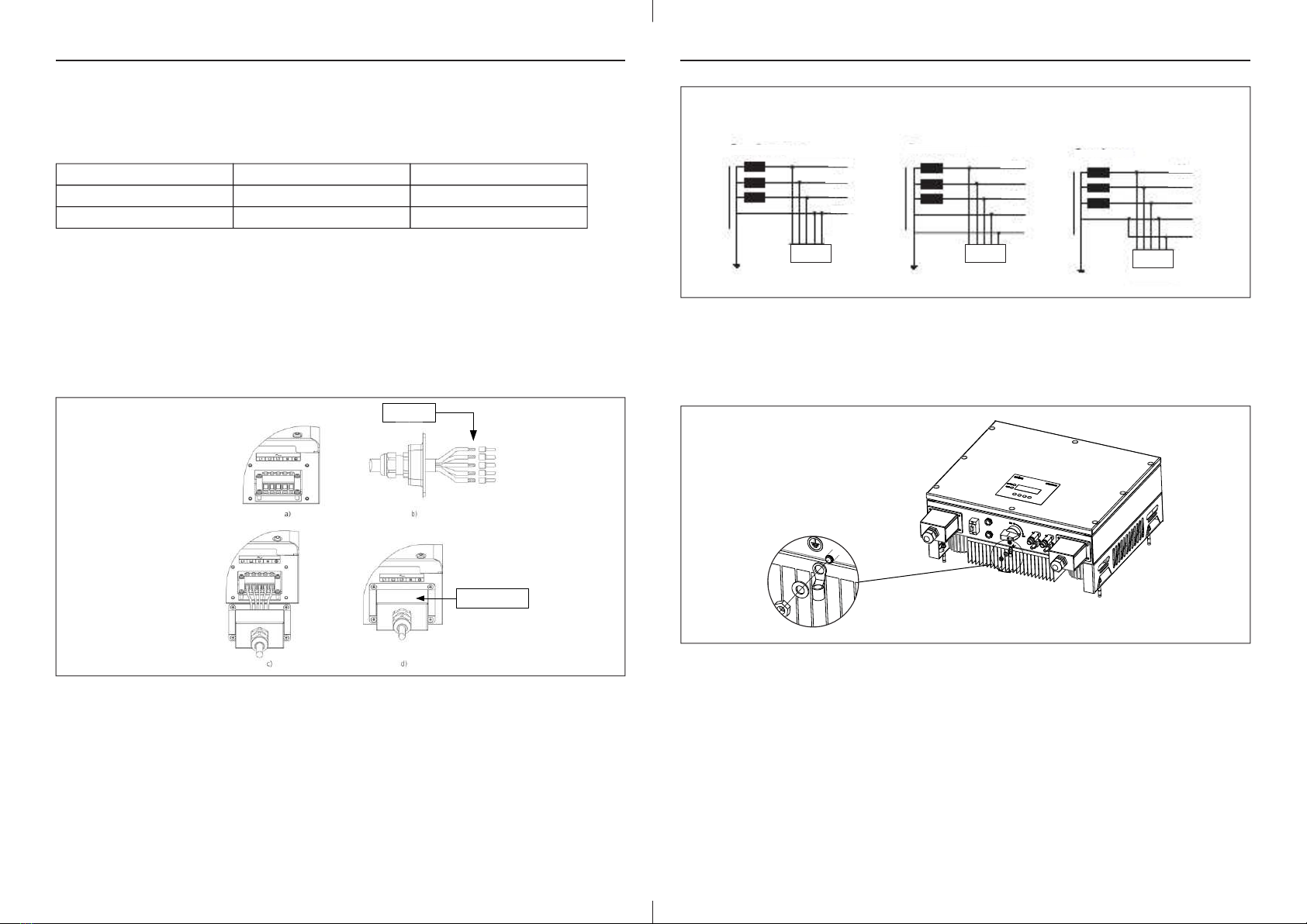
6.2.2 Grid type
Compatibility of GTI-SERIES inverter for various types of Grid connections is shown in fig 15.
Based on local grid standard there are different types of Grid connections available.
ŸGTI Series inverters support 3 phase 4 wire PE (3 -phase, N, PE) & 3 phase 3 wire
(3 -phase PE).
Fig 14
12
www.selec.com
6.2.1 Steps for AC wiring
Note - This inverter has in-build residual current monitoring device. If system installer wants to use
other residual current monitoring device then must use device which triggers in the event of residual
current of 300mA or more.
4) Fig 14(a) shows labels for AC connections.
5) Insert 5 core wire through gland and cover as shown in fig 14 (b).
6) Make connections as shown in Fig 14 (c).
7) Tighten the cover and gland properly as shown in fig 14 (d).
avoid accidental shorting of two wire.
3) Put these wires in AC Connector Board & screw it tightly.
2) Strip AC wires and put lugs using crimping tool, it will ensure no wire strands are open &
1) Use 5 core AC cables of 4 sq.mm size for AC connection.
Model Current Rating Wire Size
GTI10kW 16A 2.5 or 4 sq.mm
GTI06kW 10A 2.5 sq.mm
Grid's earth terminal must be connected to inverter's protective earth (PE) terminal as shown in
Fig 16.
6.2.3 AC Grounding
Fig 16
6.3 Communication module
GTI-SERIES inverter's Communication boards have RS-485, Dry contact & I/O connection
(Digital input) terminals as shown in fig 17.
13 www.selec.com
Transformer Transformer Transformer
L1
L2
L3
PEN
PE
L1
L2
L3
N
PE
L1
L2
L3
N
PE
GTI GTI GTI
TN-C TN-S TN-C-S
Fig 15
5 Core Wire
AC Terminal Cover
User Manual
INVERTER GTI -SERIES
User Manual
INVERTER GTI -SERIES
Other manuals for GTI Series
1
This manual suits for next models
2
Table of contents
Other Selec Inverter manuals


