Selec GTI Series User manual

Creating Best Value
SOLAR GRID TIE INVERTER
OPERATING INSTRUCTIONS
www.selec.com

2.2 Inverter overview 2
8. Maintenance and cleaning 23
5.1 Safety note before installation 6
2.5 Symbols on the inverter 4
5. Installation 6
1.3 Storage of manual 1
3.1 Safety during assembly 5
4.1 Unpacking 5
2.6 Transportation 4
2.3 Weight and dimensions 3
1. Manual Overview 1
2.1 Intended use of inverter 2
1.4 Additional information 1
5.2 Installation of inverter 7
6.1 DC connection to inverter 10
6.2 AC connections 11
4. Unpacking and accessories 5
4.2 Accessories 5
1.1 What is inside the manual 1
2. Product Overview 2
3. Safety instructions 5
1.2 Target group 1
6. Electrical connections 10
6.3 Communication module 13
6.4 Troubleshooting 20
7. Commissioning of inverter 23
7.1 Initial turn ON of inverter 23
2.4 Type label 3
2.7 Storage 4
8.2 Cleaning 24
9. Decommissioning of inverter 24
10. Technical Specification 25
10.2 Spare parts and Accessories 26
10.1 Tightening torque required 26
8.1 Maintenance 23
INDEX Page No.

1
WARNING
• Before using the inverter, please read all safety and operational instructions and warnings on the
unit and in this manual carefully.
• Selec Controls Pvt. Ltd. is not liable for any damages caused by failure to observe and follow
these instructions in the manual.
• Selec Controls Pvt. Ltd. holds the rights to make future changes in this manual and accepts no
responsibility to inform the users.
1.1 What is inside the manual ?
• This manual contains all the technical information required for the installation, operation,
maintenance and troubleshooting of the Solar - Grid Tie Inverter.
• To ensure correct and safe operation read this manual properly.
• All the important safety and operational guidelines are present in this manual.
1.2 Target Group
• The content in this manual is meant for qualified persons only.
• For safety reasons only a qualified person can install, operate, troubleshoot and repair this device.
• Qualified person should also be familiar with local requirements, rules and regulations.
NOTE
1. Manual Overview
1.4 Additional Information
• Keep this manual at a location from where it is accessible all time in case of any emergency.
• Please refer to www.selec.com for the updated version of manual
1.3 Storage of manual
• Hereby qualified person means one who has received training or has demonstrated skills and
knowledge in construction and in operation of this device.
www.selec.com
User Manual
INVERTER GTI -SERIES
2
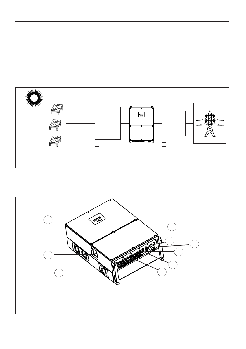
2.1 Intended use of inverter
The Inverter is a Grid Tied Solar Inverter. When sunrays fall upon the PV array, DC power is generated
by these arrays. This power is fed to the inverter as input. Inverter will convert this DC power into AC
power and feed it to three phase utility grid. GTI is 10 strings inverter with 3 independent MPPT
trackers.
GTI
2. Product Overview
As shown in Fig 1, the complete system consists of PV array, DC distribution box, GTI-SERIES
inverter, AC distribution box and utility grid.
www.selec.com
2.2 Inverter Overview
4) AC output 8) Type label
3) Communication port 7) DB9 RS485
1) Input PV terminals 5) Protective earth terminal
2) DC switch 6) LCD
Fig 1
PV 1
UTILITY GRID
DC
DISTRIBUTION
BOX
AC
DISTRIBUTION
BOX
SURGE ARRESTOR
DC BREAKER
FUSE
SURGE ARRESTOR
AC BREAKER
INVERTER
User Manual
INVERTER GTI -SERIES
PV 2
PV 3
6
2
5
8
4
3
7
1
9
9) DC Fan

Fig 3(a) Side View
Fig 3(b) Front View
C : 285mm
A : 830mm B : 580mm
2.4 Type label
Type label is present on the right hand side of inverter. Type label has information about
inverter specific characteristics, various symbols, certificates and approval.
2.3 Weight and dimensions
1) Weight of the Inverter is 86 Kilogram.
3www.selec.com
User Manual
INVERTER GTI -SERIES
A
B
C
PV GRID INVERTER
Made In India
------------------------------------------------------
IS16221-1&2
IS16169 IP65
5min
Model : GTI049WLM3PW
-----------------------------------------------------
DC Input Range : 590-1000 VDC
Max. DC Voltage : 1000 VDC
MPPT Voltage Range : 610-1000 VDC
Max. Input Current : 91A
Isc PV (Absolute maximum)
DC per MPPT : 125A
-----------------------------------------------------
AC Output : 240/415 VAC, 50Hz
3P/4W/PE, cosφ 0.8lag~0.8lead
Max. Output current : 3*84A
Apparent Power :
49kVA nom, 55kVA max
-----------------------------------------------------
Safety Level : Class 1
Ambient Temp : -25°C...+60 C°
-----------------------------------------------------
Mfg. By: Selec Controls Pvt. Ltd.,
EL-27/1 EL-27/1 PT, EL-27/2 EL-27/3,
Electronic Zone, TTC Industrial Area,
MIDC Mahape Nai Mumbai, Raigad,
Maharashtra, 400710
PV GRID INVERTER
Made In India
------------------------------------------------------
IS16221-1&2
IS16169 IP65
5min
Model : GTI033WLM3PW
-----------------------------------------------------
DC Input Range : 200-1000 VDC
Max. DC Voltage : 1000 VDC
MPPT Voltage Range : 200-1000 VDC
Max. Input Current : 26A/26A/26A
Isc PV (Absolute maximum)
DC per MPPT : 32A
-----------------------------------------------------
AC Output : 240/415 VAC, 50Hz
3P/4W/PE, cosφ 0.8lag~0.8lead
Max. Output current : 3*55A
Apparent Power :
33kVA nom, 36.3kVA max
-----------------------------------------------------
Safety Level : Class 1
Ambient Temp : -25°C...+60 C°
-----------------------------------------------------
Mfg. By: Selec Controls Pvt. Ltd.,
EL-27/1 EL-27/1 PT, EL-27/2 EL-27/3,
Electronic Zone, TTC Industrial Area,
MIDC Mahape Nai Mumbai, Raigad,
Maharashtra, 400710
PV GRID INVERTER
Made In India
------------------------------------------------------
IS16221-1&2
IS16169 IP65
5min
Model : GTI050WLM3PW
-----------------------------------------------------
DC Input Range : 200-1000 VDC
Max. DC Voltage : 1000 VDC
MPPT Voltage Range : 200-1000 VDC
Max. Input Current : 40A/30A/30A
Isc PV (Absolute maximum)
DC per MPPT : 55A
-----------------------------------------------------
AC Output : 240/415 VAC, 50Hz
3P/4W/PE, cosφ 0.8lag~0.8lead
Max. Output current : 3*84A
Apparent Power :
50kVA nom, 55kVA max
-----------------------------------------------------
Safety Level : Class 1
Ambient Temp : -25°C...+60 C°
-----------------------------------------------------
Mfg. By: Selec Controls Pvt. Ltd.,
EL-27/1 EL-27/1 PT, EL-27/2 EL-27/3,
Electronic Zone, TTC Industrial Area,
MIDC Mahape Nai Mumbai, Raigad,
Maharashtra, 400710
PV GRID INVERTER
Made In India
------------------------------------------------------
IS16221-1&2
IS16169 IP65
5min
Model : GTI030WLM3PW
-----------------------------------------------------
DC Input Range : 200-1000 VDC
Max. DC Voltage : 1000 VDC
MPPT Voltage Range : 200-1000 VDC
Max. Input Current : 30A/30A
Isc PV (Absolute maximum)
DC per MPPT : 55A
-----------------------------------------------------
AC Output : 240/415 VAC, 50Hz
3P/4W/PE, cosφ 0.8lag~0.8lead
Max. Output current : 3*55A
Apparent Power :
30kVA nom, 36.3kVA max
-----------------------------------------------------
Safety Level : Class 1
Ambient Temp : -25°C...+60 C°
-----------------------------------------------------
Mfg. By: Selec Controls Pvt. Ltd.,
EL-27/1 EL-27/1 PT, EL-27/2 EL-27/3,
Electronic Zone, TTC Industrial Area,
MIDC Mahape Nai Mumbai, Raigad,
Maharashtra, 400710

Symbol
5
MIN
IP65
4
www.selec.com
Read the manual before installing GTI-SERIES Inverters.
Do not dispose this inverter with household waste.
CE mark. The inverter complies with the requirements of applicable EC guidelines.
Protective earth terminal.
GTI-SERIES inverter complies with IP65 norms.
Description
Be careful of high voltages.
Risk of burns due to hot surfaces.
Risk of danger. Failure to observe safety information in manual may result in serious
injury or death.
Table 1
Indications on front side of inverter :
Indication Description
Alarm status.
Status of grid connection.
Red LED
Green LED
Table 2
Residual voltage Hazard. Please wait for 5 minutes before opening to ensure the
capacitors are completely discharged.
2.5 Symbol on the Inverter
While not in load condition, Inverter should be stored in clean, dry and covered space in original package.
2.6 Transportation
2.7 Storage
Our inverters are dispatched in proper electrical and mechanical condition after thorough testing and
inspection. To ensure safe and careful transportation special packaging is used. If any damage is visible,
please immediately contact your dealer or Selec Controls Pvt Ltd. Transport of the equipment, especially
by road, must be carried out with suitable means for protecting the components, in particular the electronic
components from violent shocks, humidity, vibration, etc.
User Manual
INVERTER GTI -SERIES

4. Unpacking and accessories
3.1 Safety during assembly
During transportation unpredictable damages may occur with the inverter unit and the accessories. On
receiving the unit please do thorough inspection for any visible external damages on package. If any
external visible damage is found, do not unpack inverter unit and contact the dealer as soon as
possible.
3. Safety instructions
4.1 Unpacking
• For safety reasons only a qualified person can install, operate, troubleshoot and repair this device.
Qualified person should also be familiar with local requirements, rules and regulations.
4.2 Accessories
• The GTI should be operated with permanent connection with utility grid and not recommended for
mobile use.
• Unintended use of this inverter is sole risk of the operator and manufacturer is not responsible for
any damage caused by such use.
This chapter contains safety instructions and guidelines that must be followed at all times while working
on or with the product. To prevent personal injury, property damage and to ensure long-term operation
of the product, read this section carefully and observe all safety information at all times.
WARNING
Once you unpack the unit, please ensure that all accessories are present in the box and undamaged.
Please contact your dealer if anything is missing or damaged. All the accessories present in the box
are listed as follow in Fig 4 & Table 3.
5www.selec.com
Fig 4
2
MANUAL
675
4
3
4
1
User Manual
INVERTER GTI -SERIES

6
www.selec.com
Table 3
Quantity
1
2
3
4
5
6
7
1
1
10
10
1
2
Item
4
Description
Inverter
User Manual
PV male connector
PV female connector
Earth allen screw with 2 plane & 1 spring washer with lug
Wall mount bracket (L/R)
Eye-bolt
5. Installation
5.1 Safety note before installation:
Caution
• Weight of GTI is 86 kg. Hold inverter tightly before mounting & moving.
Warning
• Avoid installing inverter near or on flammable materials.
• Hot surface of Inverter may create a burn hazard to a person who is touching the inverter, to avoid
this mount the inverter at an appropriate height.
• Mounting surface should be rigid & able to handle weight of inverter.
• Input to this inverter is DC (Direct current) which is a PV array generator. Do not connect any
other source to it.
• Make sure DC switch is at OFF position. If it is on ON position switch it to OFF position.
• Output of inverter is AC (Alternating current) which is connected to a utility grid. Power generated
from inverter is delivered to a utility grid hence it should not be connected any other AC source or
generator.
User Manual
INVERTER GTI -SERIES
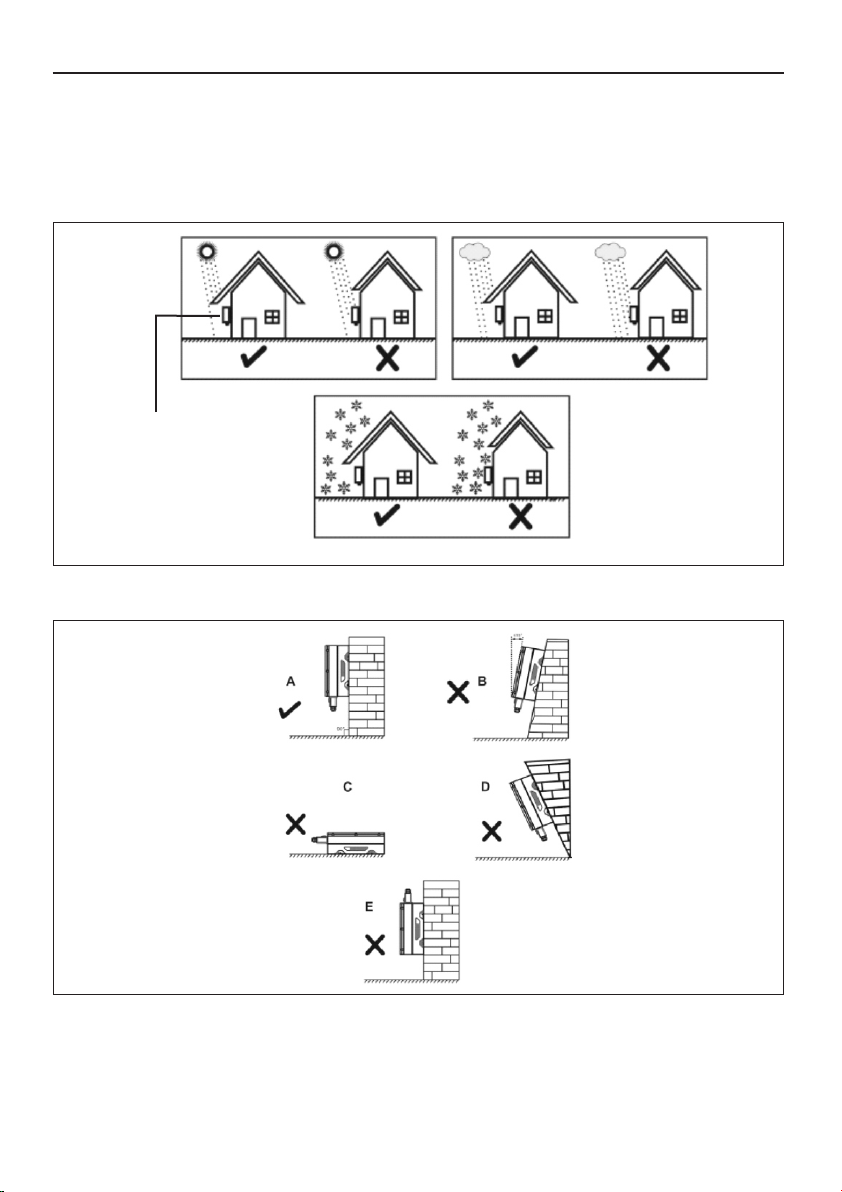
5.2 Installation of inverter
GTI is developed for use in an outdoor location with IP 65 protection but avoid
direct contact of inverter with sunlight, rainfall and snowfall. Fig 5 shows ideal locations for installation
of inverter.
• Mount the inverter on rigid, strong surface in such way that it can handle weight of the inverter.
• Mount the inverter on such a height that commissioning, decomissioning, turning ON and turning
OFF is easily possible.
NOTICE
INVERTER
AB
C
Fig 5
Ideal installing position shown in fig 6. -
Fig 6
7www.selec.com
User Manual
INVERTER GTI -SERIES

5.2.1 Clearance for installation
Install inverter on wall with minimum clearence as shown in fig 7.
To install more than one inverter in series follow fig 8. for minimum clearance. This clearance should be
provided for easy installation, removal & heat dissipation of GTI-SERIES inverter.
Fig 7
8
www.selec.com
>300mm >300mm
>300mm
>1000mm
Fig 8
>1000mm
>300mm>300mm
>200mm
>300mm
A
B
A
B
A
B
A
B
A
B
User Manual
INVERTER GTI -SERIES
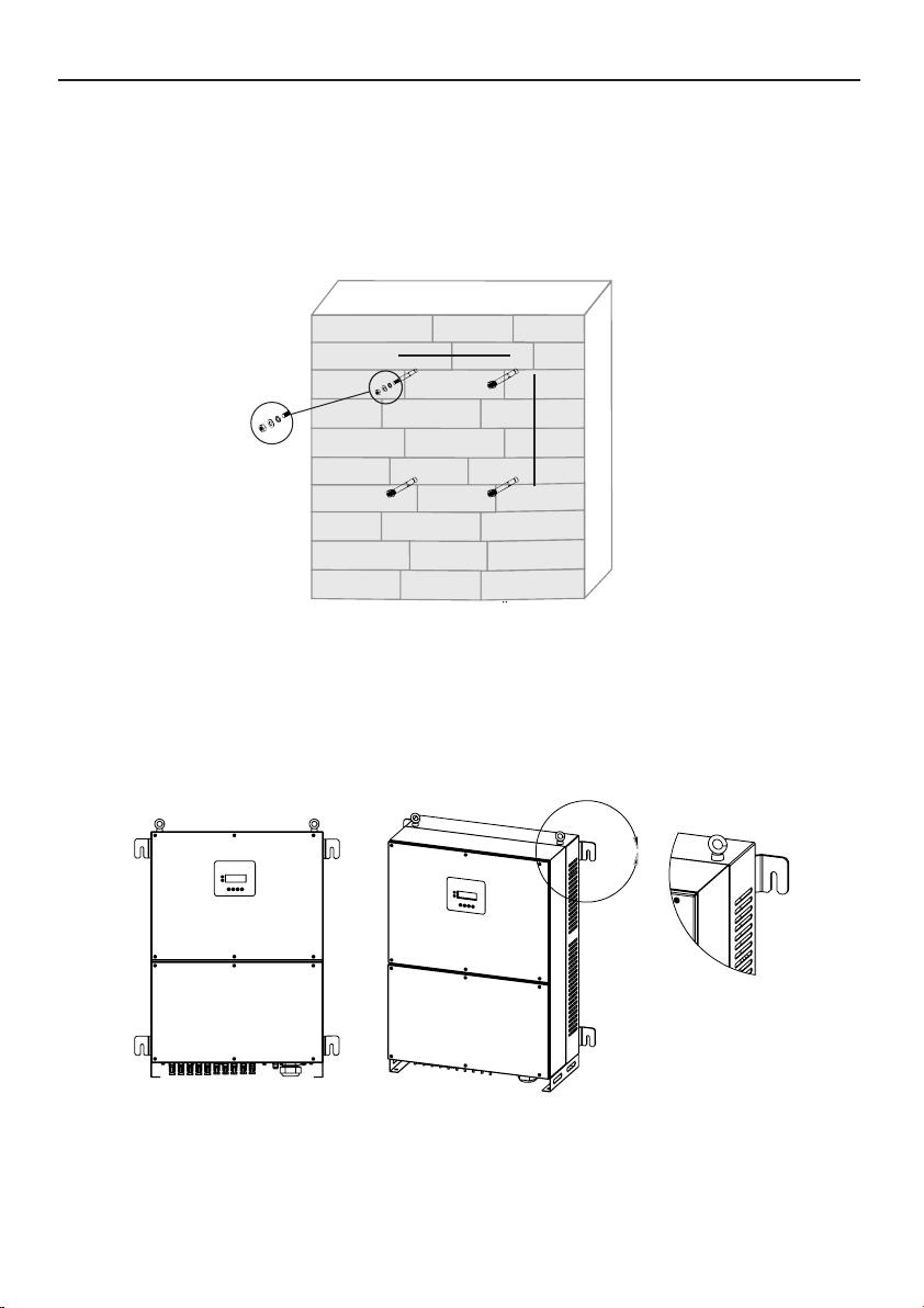
Step1 : Drill four holes on mounting surface at distance of inverter mounting position as shown in fig.9
& insert anchor bolt in holes.
5.2.2 Mounting inverter on wall:
Steps to mount inverter
Step2 : Mount inverter on anchor bolt with help of at least four people. Tighten the nut and ensure
inverter is properly fitted on anchor bolt as per fig 10.
Fig 10
Fig 9
9www.selec.com
A
B
A = 640mm
B = 666.5mm
User Manual
INVERTER GTI -SERIES

6.1. DC Connection to inverter :
4) Make sure connectors to Inverter DC terminal are connected properly.
2) Make sure PV connector's ( Male & female) polarity is proper.
1) Do not connect PV array positive terminal or negative terminal to the grounding of system.
3) Connect PV connectors as shown in fig.13
6. Electrical connections
This section helps installer, how to do electrical connection to the inverter. Electrical connection has to
be performed by qualified and authorised person only.
Check if DC Disconnect switch is in OFF position as shown in following Fig 11.
Caution
Fig 11
Warning
ŸWhenever a PV array is exposed to sunlight it supplies DC Voltage. Shock hazard may occurs if
terminals are open. Cover PV array with opaque material before commencing any wiring.
ŸEnsure string's open circuit voltage should be less than inverter's maximum input voltage.
Applying more voltage can damage inverter.
ŸDo not disconnect AC & DC cables under load condition.
Model Current Rating Wire Size
12.5A*10 4 sq.mm
10
www.selec.com
GTI050WLM3PW
12.5A*8 4 sq.mm
GTI049WLM3PW
12.5A*6 4 sq.mm
GTI033WLM3PW
12.5A*6 4 sq.mm
GTI030WLM3PW
User Manual
INVERTER GTI -SERIES

Caution
• For the purpose of over current protection use circuit breaker between inverter & utility grid.
Use 100A rated AC breaker.
6.2 AC Connections
• Before starting connection make sure that circuit breaker is OFF.
• Do not connect any load between inverter & Grid side circuit breaker.
Fig 13
11 www.selec.com
Fig 12
AB
PV1-
PV1+
PV2-
PV2+
PV3-
PV3+
WIFI / GPRS AC OUTPUT
Do not disconnect under load!
User Manual
INVERTER GTI -SERIES
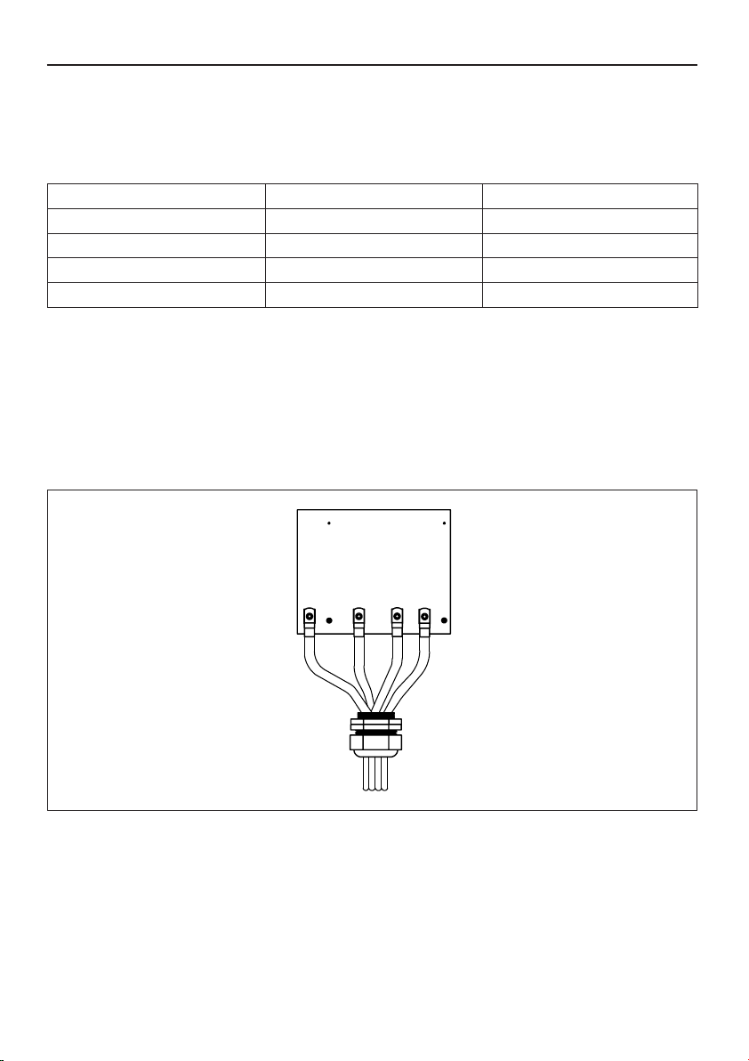
1) Use 3.5 CORE, Aluminium Conductor, PVC Insulated, Armoured Power Cables .
3) Put these wires in AC Connector Board & screw it tightly.
5) Insert 4 core wire through gland and cover as shown in fig 14 (b).
2) Strip AC wires and put lugs using crimping tool, it will ensure no wire strands are open &
avoid accidental shorting of two wire.
7) Tighten the cover and gland properly as shown in fig 14 (d).
4) Fig 14 shows labels for AC connections.
6) Make connections as shown in Fig 14 (c).
6.2.1 Steps for AC wiring
Note - This inverter has in-build residual current monitoring device. If system installer wants to use
other residual current monitoring device then must use device which triggers in the event of residual
current of 500mA or more.
6.2.2 Grid type
Compatibility of the inverter for various types of Grid connections is shown in fig 15.
Based on local grid standard there are different types of Grid connections available.
ŸGTI Series inverters support 3 phase 4 wire PE (3 -phase, N, PE) & 3 phase 3 wire
(3 -phase PE).
Fig 14
12
www.selec.com
Model Current Rating Aluminum Wire Size
GTI050WLM3PW 84A 50 sq.mm
N R Y B
GTI049WLM3PW
GTI033WLM3PW
GTI030WLM3PW
84A
55A
55A
50 sq.mm
35 sq.mm
35 sq.mm
User Manual
INVERTER GTI -SERIES

Transformer Transformer Transformer
L1
L2
L3
PEN
PE
L1
L2
L3
N
PE
L1
L2
L3
N
PE
GTI GTI GTI
TN-C TN-S TN-C-S
Grid's earth terminal must be connected to inverter's protective earth (PE) terminal as shown in
Fig 16.
6.2.3 AC Grounding
Fig 16
6.3 Communication module
The inverter's Communication boards have RS-485, Dry contact & I/O connection (Digital input)
terminals as shown in fig 17.
13 www.selec.com
Fig 15
PV1-
PV1+
PV2-
PV2+
PV3-
PV3+
WIFI / GPRS AC OUTPUT
Do not disconnect under load!
User Manual
INVERTER GTI -SERIES
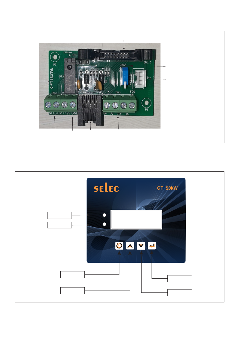
Fig 17
SUP
FROM LCD
12V
Power
RS485
DRY
CONTACT
To Dongle
DIGITAL INPUT
RS-485
Termination Switch
6.3.1 LCD KEY ANNOTATIONS
Fig 18
14
www.selec.com
ALARM
GRID
DOWN KEY
UP KEY
ENT KEY
ESC KEY
GREEN LED
RED LED
User Manual
INVERTER GTI -SERIES

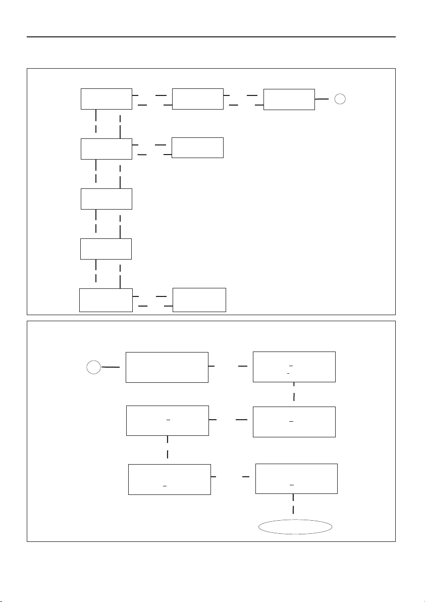
NOTE:- 1) Error will be visible on screen when they occur. (Refer table no. 7 for Error Definition).
2) When system is on & any self test error occurs screen will jump to self testing page.
3) Use Esc key to go on Home page.
6.3.2 LCD Flow Chart
15 www.selec.com
PRESS ENT KEY THEN DOWN KEY
ENT KEY
UP KEY
DOWN KEY
UP KEY
ENT KEY
ESC KEY
UP KEY
DOWN KEY
DOWN KEY
UP KEY
DOWN KEY UP KEY
DOWN KEY UP KEY
Pv2: 0.0V 0.0A
PV2 PWR: 0.0W
ADC sencing ERR
UP KEY
DOWN KEY
DOWN KEY
DOWN KEY
UP KEY
GTI 50KW
SELF TESTING...
NO ERR
GRID CONNECT TM
45
E-DAY : 3.2kWh
E-TOT : 3.6kWh
Pv1: 0.0V 0.0A
PV1 PWR: 0.0W
Pv3: 0.0V 0.0A
PV3 PWR: 0.0W
Pv1 STR CURRENTS
S1 0A S2 0A
S3 0A S4 0A
S3 0A
E-W : 3.2kWh
E-M : 3.2kWh
DOWN KEY
Press Up Key
UP KEY
L1 0.0V 0.0A
L2 0.0V 0.0A
ERROR
SCREENS
GRID IS
PRESENT
GRID CONNECT
TM IS ZERO
ERROR
DOWN KEY UP KEY
S3 0A
DOWN KEY UP KEY
DOWN KEY UP KEY
Pv3 STR CURRENTS
S1 0A S2 0A
L3 0.0V 0.0A
GRID FREQ 0.0Hz
ACTV PWR 0.0 W
RCTV PWR 0.0 W
APPR PWR 0.0W
IRES 0.0 Kohm
RCMU 0.0 mA
DOWN KEY UP KEY
DOWN KEY UP KEY
DOWN KEY UP KEY
DOWN KEY UP KEY
DOWN KEY UP KEY
ADC sencing ERR
DOWN KEY UP KEY
ADC sencing ERR
DOWN KEY UP KEY
ADC sencing ERR
DOWN KEY UP KEY
OVER CURRENT
DOWN KEY UP KEY
OVER CURRENT
DOWN KEY UP KEY
OVER VOLTAGE
DOWN KEY UP KEY
OVER VOLTAGE
DOWN KEY UP KEY
OVER VOLTAGE
DOWN KEY UP KEY
OVER VOLTAGE
DOWN KEY UP KEY
UNDER VOLTAGE
DOWN KEY UP KEY
UNDER VOLTAGE
DOWN KEY UP KEY
TEMPRATURE
DOWN KEY UP KEY
DC LINK
DOWN KEY UP KEY
FREQ ERROR
INV STATUS : OFF
PHASE SEQ : CW
Pv2 STR CURRENTS
S1 0A S2 0A
DOWN KEY UP KEY
PRESS ENT KEY THEN
PRESS DOWN KEY
DOWN KEY
UP KEY
User Manual
INVERTER GTI -SERIES
6.3.2.1 LCD KEY FUNCTIONALITY
NOTE : 1) Press UP key to scroll around digit.
2) Press DOWN key to change digit.
16
www.selec.com
BL Ver : 18.0-1
SCAN : 3mS/sc
DOWN KEY
UP KEY
ENT KEY
ESC KEY
1-SYSTEM INFO
2-COM SETTING
3-MODBUS DATA
SLAVE ID : 001
115K 8N1
DATE : 26-01-2021
TIME : 11:46:23
4-DEBUG MODE
5- SERIAL NO
1
SERIAL NO
C502102N10-023
ENT KEY
ESC KEY
ENT KEY
ESC KEY
ENT KEY
ESC KEY
DOWN KEY
UP KEY
DOWN KEY
UP KEY
DOWN KEY
UP KEY
a) LONG PRESS ESC KEY
DATE : 15-01-2021
TIME : 11 : 46 : 23
DATE : 15-01-2021
TIME : 11 : 46 : 23
DATE : 25-01-2021
TIME : 11 : 46 : 23
DATE : 25-01-2021
TIME : 11 : 46 : 23
DATE : 25-01-2021
TIME : 11 : 46 : 23
DATE : 25-01-2021
TIME : 21 : 46 : 23
Change Saved
ENTER KEY
DOWN KEY
UP KEY
DOWN KEY
ENTER KEY
1
b) TO CHNAGE DATE / TIME
ENTER KEY
User Manual
INVERTER GTI -SERIES

17 www.selec.com
c) LONG PRESS UP KEY
ENT
ESC
ESC
DOWN
UP
ENT
DOWN DOWN
ESC
ENT
DOWN
DOWN
ENTER
PASSWORD
ACTIVE POWER
(SET%) 10.00% POWER FACTOR
VAL : 1.00
MAIN DSP ID:1
SW:1 HW:1 RED ID:1
SW:1 HW:1
POWER FACTOR
MODE LEAD
UP KEY
DOWN KEY
ERROR LOG
INVERTER
INFO
SR.NO. DATE
ERR TIME
UP KEY
DOWN KEY
INVERTER
SETTING
Note : 1) Error log will store last 20 errors.
2) Sr. No : Total No. of errors.
3) Date : Date of error occurs.
4) Time : Time at which error occurs
5) Err : Log code will appear ( Refer table No. 6 )
SET VEN VAL IS 0
SELEC INS VAL 0
DRY CONTACT
DISABLE
TO CHANGE PWD
PRESS ENT
DOWN
ENTER PWD
XXXX
RE-ENT PWD
XXXX
ENT
ENT
GO TO HOME PAGE
ENT
PRESS ENT TO
SET GRID
VOLT LIMIT
ESC
ENT
LOWER LIMIT 200.0
UPPER LIMIT 280.0
DOWN
PRESS ENT TO
SET GRID
FREQ. LIMIT
ESC
ENT
LOWER LIMIT 48.0
UPPER LIMIT 52.0
DOWN
DOWN
User Manual
INVERTER GTI -SERIES

TO CHANGE PWD
PRESS ENT
Enter PWD
0000
Enter PWD
0000
Enter PWD
1000
Enter PWD
1100
Enter PWD
1000
Re-ENT PWD
0000
Re-ENT PWD
0000
Re-Enter PWD
1000
Re-ENT PWD
1000
Re-Enter PWD
1100
Password Changed
ENTER KEY
UP KEY
DOWN KEY
UP KEY
DOWN KEY
ENTER KEY
UP KEY
DOWN KEY
UP KEY
ENTER KEY DOWN KEY
NOTE : 1) Press UP key to scroll around digits.
2) Press DOWN key to change digits.
d) TO CHANGE PASSWORD
6.3.3 Communication module connections
Pin description of RS-485 Communication terminal is given below in Table 5
6.3.3.1 RS-485 Configuration
• Connect A+ & A- pin of RS-485 port to the Data +, Data -.
Data Format:
Baud rate : 9600
Data bits : 8
Stop bit : 1
Following data format is used for Communication
Parity : N
Connecting single inverter for RS-485 communication :
Pin Notation
A+
A-
Function
Data +
Data -
Table 5
18
www.selec.com
User Manual
INVERTER GTI -SERIES
Other manuals for GTI Series
1
This manual suits for next models
3
Table of contents
Other Selec Inverter manuals


