TICA TIMS-S Series User manual

INVERTER MULTI
SYSTEM UNIT
Applicable to: TIMS-S/ST/SA/SRYA series
https://tica.pro
TICA PRO LLC Tel: +7(495)127-79-00; +7(969)190-85-85 E-mail: [email protected] www.tica.pro

Contents
Safety Precautions .................................................................................................................. 5
Installation of ODU .................................................................................................................. 6
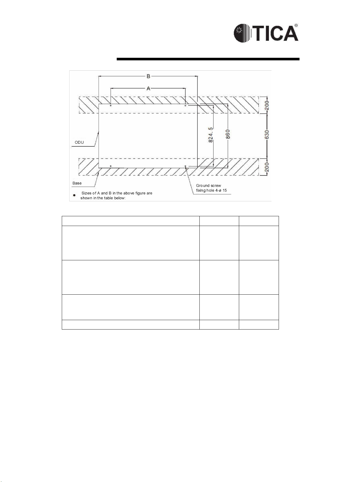
Dimension ....................................................................................................................................... 8
Installation space ..............................................................................................................10
Handling........................................................................................................................................14
Placement ...........................................................................................................................13
Installation of Refrigerant Piping .........................................................................................15
Precautions for the installation of piping: .........................................................................16
The choice of the refrigerant pipe diameter .....................................................................20
Installation of branch pipes .............................................................................................. 21
Refrigerant piping length .................................................................................................. 25
Air Tightness Test, Vacuuming and Supplementing Refrigerant ....................................26
Air tightness test ...............................................................................................................26
Vacuumizing: ....................................................................................................................26
Supplementing refrigerant ................................................................................................28
Electric Control Installation ..................................................................................................29
Wiring cautions .................................................................................................................29
Wiring specifications .........................................................................................................30
Electrical wiring ................................................................................................................ 31
Communication wiring ......................................................................................................31
ODU Control Panel ................................................................................................................ 32
Code settings ....................................................................................................................32
Settings of relevant keys .................................................................................................. 35
Digital display ................................................................................................................... 37
Trial Operation ....................................................................................................................... 39
Before trial operation ........................................................................................................39
Trial operation .................................................................................................................. 39
Trial operation check ........................................................................................................40
Description of Hazardous Substances ............................................................................... 41
TICA PRO LLC Tel: +7(495)127-79-00; +7(969)190-85-85 E-mail: [email protected] www.tica.pro

Application Form for Debugging Inverter VRF Air Conditioning Unit (Filled by Installer)
Full name of the installer:___________________________________________________________
Address of the installer:____________________________________________________________
Owner's name or employer:_________________________________________________________
Person to contact:_______________________________Tel:______________________________
Installation site:_________ Province _________ City ____________________________________
Unit model: ___________________________
IDU bar code:___________________________
ODU bar code:___________________________
Distributor:________________________
Person to contact:_________________________
Tel:______________________________
Fax:____________________________________
Installer:__________________________
Person to contact:_________________________
Tel:______________________________
Fax:____________________________________
The following items are to be filled by the installer correctly and faxed to TICA Factory 400 Center 48 hours
before boot debugging, so that the debugging can be arranged in due time.
Fax:862585323095;
Tel:4008601601 In case the form contents are different from the real situation, causing the experts unlikely
to conduct debugging on site, the installer must be liable for labor and travelling expenses incurred to the
debugging experts.
Contents to be Checked and Confirmed by Installer
Before installation, ask the installer to carefully read through the manuals and relevant requirements
attached to the unit.
1. Check installation position
a. Whether heat dissipation and ventilation for ODU meets requirements for distance
Yes ( )
No ( )
b. Whether ODU is installed on a base firmly and with vibration damping measures
applied
Yes ( )
No ( )
c. Whether IDU is provided with vibration damping measures and properly fastened
Yes ( )
No ( )
d. Whether there is space for maintenance
Yes ( )
No ( )
2. Check electrical system before installation
Yes ( )
No ( )
a. Whether air switch capacity and power wire diameter meet unit requirements
Yes ( )
No ( )
b. Whether correctly wired and whether wiring terminal is pressed and completely
connected
Yes ( )
No ( )
c. Whether neutral line and grounding wire are connected in accordance with
electrical codes
Yes ( )
No ( )
d. Whether the distribution of control wire and power wire meets anti-interference
requirements
Yes ( )
No ( )
e. Whether the length of control wire and power wire is proper
Yes ( )
No ( )
3. Check refrigerating system before installation
Yes ( )
No ( )
a. Whether refrigerant duct meets factory requirements in terms of its diameter and
thickness
Yes ( )
No ( )
b. Whether the length of refrigerant duct meets relevant requirements
Yes ( )
No ( )
c. Whether added nitrogen for welding refrigerant duct to protect air conditioning unit
Yes ( )
No ( )
d. Whether cleaned refrigerant duct
Yes ( )
No ( )
e. Whether used nitrogen for holding pressure to test leakage
Yes ( )
No ( )
f. Whether vacuumized refrigerating system against installation manual
Yes ( )
No ( )
g. Whether supplemented refrigerant according to standard
Yes ( )
No ( )
TICA PRO LLC Tel: +7(495)127-79-00; +7(969)190-85-85 E-mail: [email protected] www.tica.pro

Application Form for Debugging Inverter VRF Air Conditioning Unit (Filled by
Installer)
4. Check air duct system before installation
a. Whether the installation of air duct system is designed by professionals
Yes ( ) No ( )
b. Whether external residual pressure matched actual resistance of air duct
Yes ( ) No ( )
c. Whether air duct system is provided with static pressure box for air supply and
return
Yes ( ) No ( )
d. Whether air flow organization of indoor air supply and return is reasonable
Yes ( ) No ( )
e. Whether air duct is insulated
Yes ( ) No ( )
f. Whether air valve is reasonably set
Yes ( ) No ( )
g. Whether return air inlet or IDU is equipped with clean filter
Yes ( ) No ( )
h. Whether equipped with air return duct in the case of ceiling air return
Yes ( ) No ( )
i. Whether there is fresh air device
Yes ( ) No ( )
j. Air supply and return mode: 1 bottom air supply and side air return; 2 side air
supply and side air return
Yes ( )
5. Check indoor condensate water system before installation
a. Pour water into drain pan to check whether condensate water could be
discharged smoothly and whether there is leakage
Yes ( ) No ( )
b. Check whether condensate water pipe is tightly sealed to prevent condensation
on the surface of pipe
Yes ( ) No ( )
c. Whether water trap is designed in accordance with the manual attached to the
unit
Yes ( ) No ( )
6. Preparation before debugging
A. Whether power voltage is in the normal range of the unit and whether the
three-phase balance is less than 2%
Yes ( ) No ( )
b. Ensure the power is not temporary
Yes ( ) No ( )
d. Whether the clients and Party A's inspection experts are in place in time
Yes ( ) No ( )
e. Whether there are sufficient facilities (ladder and lifting table) to ensure normal
work of operators
Yes ( ) No ( )
f. Whether the unit is pre-heated for 24 hours before powering on for debugging
Yes ( ) No ( )
7. Other circumstances
Date of requiring debugging: by ___MM_____DD___YYYY
Applicant (seal):
Signature: Date:
TICA PRO LLC Tel: +7(495)127-79-00; +7(969)190-85-85 E-mail: [email protected] www.tica.pro

5
Safety Precautions
Caution: Read this manual carefully before installation and use of the unit. The following
standard is applied to this product
This installation manual is applied to TICA TIMS-S/ST/SA/SRYA
series R410A refrigerant inverter VRF air (cooling only) conditioning
units.
The manual is subject to change based on improvement on air
conditioners without further notice.
Preparation before
installation
● Installation shall be left to
a licensed professional.
Users shall not install,
repair or displace the air
conditioning unit by
themselves.
● Be sure to use a
dedicated power circuit.
Make sure the supply
voltage fluctuates within
10% of rated voltage.
Power supply should be
separate from welding
transformer because the
latter may cause large
voltage fluctuation.
● Get a licensed electrician
to install the unit
according to national and
local power standard, and
to check whether line
capacity meets
requirements and
whether power lines are
loose or damaged.
● "Electrical control
schematic diagram" is
attached to the back side
of cover plate of ODU
control box. Please keep
the manual properly for
further reference.
Precautions during installation
● Do not touch heat exchanger
fins. Otherwise, it may cause
damage to the fins or reduced
performance for the unit or
finger injury.
● The cover plate for control box
must be fastened to prevent
incoming of dust and water.
The electrical parts must be
water-proof and away from
water sources, otherwise
electric shock or fire may be
caused.
● After installation, be sure to
make an air tightness check
whether there is pipeline
leakage.
Precautions for using R410A
refrigerant devices
● Please supplement
refrigerating system with liquid
refrigerant. In the case of
gaseous refrigerant,
composition of refrigerant in
the system may change.
● Do not mix into other
refrigerants.
● Do not use the following tools
ever used for common
refrigerants (such as R22):
pipeline pressure test devices,
charge hoses, leakage
detection devices, refrigerant
charge base, and refrigerant
recovery devices.
● Make sure to use vacuum
pump dedicated for R410A
series.
Precautions at trial operation
● When the system is powered
on for the first time or after
being left unused for a long
time, ODU power must be
connected 24 hours before
use. Otherwise, the
compressor may be burnt
(make sure the air
conditioner is in standby
mode at the seasons they are
needed most).
● Do not turn on the air
conditioner when the panel or
protection screen is removed.
The moving parts inside the
air conditioner may hurt
people or other objects.
● Do not touch refrigerant
pipeline during operation or
just at the end of operation.
The pipeline of the air
conditioner may be very hot
or cold during its operation,
which may lead to scald or
frostbite.
● Do not turn off power
immediately after the unit
stops. Wait at least for five
minutes to prevent water
leakage.
● Please cut off general power
supply during seasons the air
conditioners are not used to
prolong the service life and
save energy.
● All the IDUs and ODUs of the
same system must be
supplied with power
simultaneously.

6
Installation of ODU
Standard mode
The single outdoor unit starts from 8HP and increases with 2HP, up to 34HP
Model
8HP
10HP
12HP
14HP
16HP
TIMS080-S
TIMS080-SA
TIMS080-ST
TIMS252CSRYA
TIMS100-S
TIMS100-SA
TIMS100-ST
TIMS285CSRYA
TIMS120-S
TIMS120-SA
TIMS120-ST
TIMS335CSRYA
TIMS140-S
TIMS140-SA
TIMS140-ST
TIMS400CSRYA
TIMS160-S
TIMS160-SA
TIMS160-ST
TIMS450CSRYA
18HP
20HP
22HP
24HP
26HP
TIMS180-S
TIMS180-SA
TIMS180-ST
TIMS200-S
TIMS200-SA
TIMS200-ST
TIMS220-S
TIMS220-SA
TIMS200-ST
TIMS240-S
TIMS240-SA
TIMS260-S
TIMS260-SA
28HP
30HP
32HP
34HP
TIMS280-S
TIMS280-SA
TIMS300-S
TIMS300-SA
TIMS320-S
TIMS320-SA
TIMS340-SA
Maximum quantity of connectable indoor unit
ODU Capacity
8HP
10HP
12HP
14HP
16HP
18HP
20HP
Quantity of connectable IDU
14
16
19
22
23
31
33
ODU Capacity
22HP
24HP
26HP
28HP
30HP
32HP
34HP
Quantity of connectable IDU
34
35
35
36
38
40
42

7
Installation of ODU
Dimension
Model:TIMS080-S/SA/ST TIMS100- S/SA/ST TIMS120- S/SA/ST
TIMS252CSRYA TIMS285CSRYA TIMS335CSRYA
Model:TIMS140-S/SA/ST TIMS160-S/SA/ST TIMS180-SA/ST
TIMS400CSRYA TIMS450CSRYA

8
Installation of ODU
Dimension
机型:TIMS180-S TIMS200- S/SA/ST TIMS220- S/SA/ST TIMS240- S/SA
机型:TIMS260- S/SA TIMS280- S/SA TIMS300- S/SA TIMS320- S/SA TIMS340-SA

9
Installation of ODU
Installation space
Requirements for installation position
● The installation position shall have sufficient strength to bear the unit weight and its
vibration during operation. If the ODU is installed on a roof, make sure the roof is strong
enough and water-proof.
● The ODU shall be installed in a well ventilated place to ensure good heat exchange.
● Places unsuitable for installation:
▲ The place where acid or alkaline substance or corrosive gas(e.g., sulfur dioxide and
hydrogen sulfide) may be produced, easily corroding the unit and leading to
refrigerant leakage.
● Places where air conditioning units must not be installed
● ▲ The place where flammable gas or volatile combustibles may be produced. If
flammable gas leaks and accumulates around the unit, the unit may explode.
▲ Do not install the ODU where it is exposed directly to strong wind or typhoon. When
conditions permit, add auxiliary equipment to prevent water, snow or direct sunshine.
▲ Do not install the outdoor unit just below the edge of the roof, to prevent the unit
failure caused by the dropping of rubbles or ice particles. If installing the outdoor unit
in this position is unavoidable, mount a protective shed above it.
Installation of snow protection facilities
● Install snow protection facilities in the snow area, such as
the snow protection cover and shed.
● Inadequate snow protection facilities will result in a high
probability of malfunction.
● Appropriately raise the bracket stand to avoid snow
accumulation.
Requirements for ODU installation space
● Make sure there is enough space above the unit.
● The side with TICA symbol attached shall be the front side of ODU.
● Make sure that the surrounding walls are not higher than the specified value below:
front: 1500 mm, rear: 500 mm, left and right: unlimited
● Otherwise, the maintenance distances at front or rear side should be increased by H/2, as
shown in the following figure:

10
Installation of ODU
Installation space of a unit:
1. Installation space of a unit
A unit should be installed in space surrounded by walls. The walls at its both sides is
unlimited in height.
When the front and one side of the ODU are in open areas

11
Installation of ODU
2. Unit installation in a single row
The unit should be installed in space surrounded by walls
The front and one side of the ODU are in open areas
3. ODU Installation in the same direction
space surrounded by walls

12
Installation of ODU
The front and one side of the ODU are in open areas
3. Unit installation back to back
The front and one side of the ODU are in open areas
The unit is surrounded by walls

13
Installation of ODU
Handling
Notes:
● Fragile and handle with care.
● The degree of inclination shall not exceed 30° while handling (do not put the unit on
its side).
● Keep heat exchange fins safe while handling and installing the unit. In case of any
damages, please use fin comb to fix it up.
● Properly dispose of packaging bags and prevent kids from playing with them.
● Use forklift to handle: be careful when inserting the fork into the pocket at the bottom,
and prevent fork from damaging the unit or the unit bottom.
● Use crane to handle: tighten hoisting rope according to what is shown in the figure,
and keep the unit weight even during hoisting.
● Use two hoisting ropes at least 8 m long and about 20 mm in diameter to support the
unit weight. Do not use tying band of the unit for handling.
● After the wooden framework is removed: use paper or cloth as pad between hoisting
rope and the unit to prevent damages to the unit body.
Placement
● Make sure the ODU is placed firmly at a level place to prevent vibration and noises.
● Use a base larger than the width of ODU's support legs (66 mm) to support the unit.
● The shock-absorbing pads shall cover the entire bearing surface of the base.
● The unit base shall be at least 200 mm higher above the ground.
● Around the base there should be drain to ensure that the condensate water
generated during operation could flow out.

14
Installation of ODU
Model
A
B
TIMS080-S ~ TIMS120-S
TIMS080-SA ~ TIMS120-SA
TIMS080-ST ~ TIMS120-ST
TIMS252、285、335CSRYA
728 mm
930 mm
TIMS140-S ~ TIMS160-S
TIMS140-SA ~ TIMS180-SA
TIMS140-ST ~ TIMS180-ST
TIMS400、450CSRYA
1038 mm
1240 mm
TIMS180-S ~ TIMS220-S
TIMS200-ST
TIMS200-SA ~ TIMS240-SA
1375 mm
1500 mm
TIMS260-SA ~ TIMS340-SA
1745 mm
1900 mm

15
Installation of Refrigerant Piping
● Concrete foundation: the foundation shall be above the ground for at least 150 mm.
● Use anchor bolts, nuts and pads to fasten the ODU tightly to the base.
Caution: shock-absorbing pads need to cover the entire bottom of the unit, and the pad
thickness is greater than or equal to 20 mm.
● For anti-corrosive models: use rubber pads. If the nut joints get loose, the unit will not
be corrosion proof.

16
Installation of Refrigerant Piping
Precautions for the installation of piping:
● Use clean piping that is free from dust, moisture or any other substances.
● Store all the pipelines needed for installation indoors, and keep two ends of pipelines
sealed till welding.
● Pass copper pipes into the holes at wall and seal the holes to prevent dirt coming in.
● Do not do ODU piping work on rainy days, lest that moisture and dirt would enter the
pipelines.
● Try to reduce bended piping and use bends with larger radius.
● When connecting refrigerant piping, the stop valve of ODU shall be closed
completely after refrigerant piping between ODU and IDU is done, and refrigerant
leakage test and vacuumizing process are finished.

17
Installation of Refrigerant Piping
Definition
Limit (actual length)
Remarks
H1*1
Level difference between the IDU and ODU
When the ODU is at
the upper position: <
50 m
When the ODU is at
the lower position: < 40
m
H2*1
Level difference among IDUs
< 20 m
L1*2
The distance from the farthest IDU to the
first branch pipe of the IDU.
< 40 m
LM
The distance between the ODU and indoor
first branch pipe
< 90 m
Over 40 m:
Main gas pipe size
should be increased
by one level
L1-L2
T The distance from the farthest IDU to the
first branch pipe of the IDU.
< 40 m
L3
Distance from the IDU to the nearest
branch pipe
< 40 m
Total L
Total length of piping (total length of all
liquid pipes or gas pipes of the system)
Equivalent length <
1000 m
*1: Contact TICA's engineers when exceeding the above limits.
*2: If it exceeds 40 m, the remarks on the next page shall be met.
*3: The total refrigerant quantity of the unit (≤ 32 HP) should not be greater than 52.0 kg, and
that of the 34 HP unit should not be greater than 60.0 kg. Otherwise, the unit may fail to
operate safely and reliably. Please consult TICA's engineers for details.

18
Determination of diameter of branch pipe of the IDU
The IDU is equipped with branch pipes h~p. Refer to the following table for the selection of the branch
pipe size. Unit: mm
IDU capacity
When the length of the branch pipe ≤ 10
m (outer diameter x minimum wall
thickness)
When the length of the branch pipe > 10 m
(outer diameter x minimum wall thickness)
A (x100W)
Gas side
Liquid side
Gas side
Liquid side
A < 71
φ12.7x0.8
φ6.35x0.8
φ15.9x1.0
φ9.5x0.8
A > 71
Piping according to the normal pipe diameter
Note: In order to ensure the best use effect of the IDU, control the length of the branch pipe within 10 m
(shall not exceed 30 m), otherwise the indoor heat exchange effect will be affected.

19
Installation of Refrigerant
Piping
Remarks: The equivalent longest piping distance from the IDU to components of the first
branch pipe shall be no more than 40 m. However, when all the following conditions are met, it
is allowed to extend the length to 90 m. (in the case of "using TICA branch pipe".)
Required conditions
Legends
1. The diameter of the pipe
between the components of
the first branch pipe and those
of the last branch pipe needs to
be increased. (Make the
variable diameter pipe on the
site); If the piping diameter is
the same with that of the main
pipe, it does not need to be
increased.
b + c + d + e + f + g + p ≤ 90 m;
The piping diameters of b, c, d,
e, f, g need to be increased
The piping size shall be increased
as follows
Φ9.5→Φ12.7 Φ12.7→Φ15.9
Φ15.9→Φ19.1 Φ19.1→Φ22.2
Φ22.2→Φ25.4 Φ25.4→28.6
Φ28.6→Φ31.8 Φ31.8→Φ34.9
Φ34.9→Φ38.1
2. When calculating the total
extension length, the actual
length of the preceding pipes
must be doubled. (except for
main pipe and pipes without
increased pipe diameter.)
a + b x 2 + c x 2 + d x 2 + e x 2 +
f x 2 + g x 2 + h + I + j + k + l + m
+ n + p ≤ 1000 m
3. Distance from the IDU to the
nearest branch pipe
component ≤ 40 m
h, i, j, l, m, n, p ≤ 40 m
4. Distance difference between
(the ODU to the farthest IDU)
and (the ODU to the nearest
IDU) ≤ 40 m
The farthest IDU 8
The nearest IDU 1
Farthest IDU-nearest IDU
(a+b+c+d+e+f+g+p) - (a+h) ≤ 40
m

20
Installation of Refrigerant
Piping
Direct selection of refrigerant piping
The copper pipe for main pipelines (LM) shall have the sizes chosen from the following table based on
the total capacity of ODUs at the upper reaches (the ones unlabeled can be generally applied)
ODU
capacity
(HP)
Piping length (LM + L1) < 90 m
Main pipe length (LM) < 40 m
Piping length (LM + L1) < 90
m
Main pipe length (LM) > 40 m
Piping length (LM + L1)> 90 m
Liquid pipe (mm)
Gas pipe
(mm)
Liquid pipe (mm)
Gas pipe
(mm)
Liquid pipe (mm)
Gas pipe
(mm)
8
9.52(-SA/ST)
12.7(-S/CSRYA)
22.23
9.52(-SA/ST)
12.7(-S/CSRYA)
25.4
12.7(-SA/ST)
15.88(-S/CSRYA)
25.4
10
9.52(-SA/ST)
12.7(-S/CSRYA)
22.23
9.52(-SA/ST)
12.7(-S/CSRYA)
25.4
12.7(-SA/ST)
15.88(-S/CSRYA)
25.4
12
12.7
25.4
12.7
28.58
15.88
28.58
14
12.7
28.58
12.7
31.75
15.88
31.75
16
12.7
28.58
12.7
31.75
15.88
31.75
18
12.7(-SA/ST)
15.88(-S)
28.58
12.7(-SA/ST)
15.88(-S)
31.75
15.88(-SA/ST)
19.05(-S)
31.75
20
15.88
28.58
15.88
31.75
19.05
31.75
22
15.88
28.58
15.88
31.75
19.05
31.75
24
15.88
28.58
15.88
31.75
19.05
31.75
26
19.05
31.75
19.05
34.92
22.23
34.92
28
19.05
31.75
19.05
34.92
22.23
34.92
30
19.05
31.75
19.05
34.92
22.23
34.92
32
19.05
31.75
19.05
34.92
22.23
34.92
34
19.05
34.92
19.05
38.1
22.23
38.1
This manual suits for next models
42
Table of contents
Other TICA Inverter manuals
Popular Inverter manuals by other brands

Agilent Technologies
Agilent Technologies U9391C Operating and service manual

SIGLENT
SIGLENT SDG1000X Series quick start

Nature Power
Nature Power 37750 user manual

Ryobi
Ryobi RY907000FI Operator's manual

Mitsubishi Electric
Mitsubishi Electric 800 Series instruction manual

Karda
Karda KD4000-2S Series user manual

Grupo Urrea
Grupo Urrea Surtek IC5500 User manual & warranty

Tektronix
Tektronix AFG31000 Series user manual

Victron energy
Victron energy Multi RS Solar manual

Ultimate Power
Ultimate Power LP Series user manual

Emerson
Emerson SKA1100025 Getting started guide

opti-solar
opti-solar GT Series Installation and operation manual