Selenium DT 2006S User manual

1
User Manual
Digital Speaker Processor
DT 2006S

2
1 TABLE OF CONTENTS
1TABLE OF CONTENTS...........................................................Erro! Indicador não definido.
2BEFORE USING......................................................................Erro! Indicador não definido.
3INTRODUCTION......................................................................Erro! Indicador não definido.
4CHARACTERISTICS ...............................................................Erro! Indicador não definido.
4.1
Front Panel......................................................................................... Erro! Indicador não definido.
4.2
Rear Panel .......................................................................................... Erro! Indicador não definido.
5Operation ................................................................................Erro! Indicador não definido.
5.1
Re-configuration ................................................................................ Erro! Indicador não definido.

3
2 BEFORE USING
Please read these instructions carefully before using this product.
1. This product needs to be grounded. This will avoid malfunctioning and will lower the risk of
electric shock. The product has a 3-pin power cable with a conductor and plug with a
ground wire. It is important to plug in this product with its own power cable into an
appropriate electrical outlet.
2. CAUTION: a wrong connection to the equipment or without grounding could result in an
electric shock. Consult an electrician if you do not have an electrical network with grounding
or a specific electrical outlet. Do not change the product's power cable.
3. Protect the equipment from water or any other liquid.
4. Install the product in a well-ventilated place.
5. Keep the product away from sources of heat or other products that produce heat.
6. Unplug the product if you are not going to use it for a long period of time.
7. Do not pull the wire when unplugging the equipment; pull firmly at the plug.
8. Do not put anything on top of the power cable, neither install it in a place of high traffic of
people or equipment since this could crush or damage it in some way.
9. Protect the product from being dropped or hit.
10. If the product presents any problem or you notice a drop in its performance, bring the
product to the technical assistance support closest to you.
11. Do not open the product neither try to check it or change it. Any problem that may arise
should be fixed by the technical assistance trained staff.
12. CAUTION: This product can generate sound levels that can cause permanent hearing loss.
Do not use the product for long periods of time at a high volume or at uncomfortable levels.
Mark an appointment with an ear doctor in the case of hearing loss or discomfort.
13. The device should only be cleaned with a dry, soft rag. A soft-bristle brush can help clean
the harder-to-clean areas. Never use solvents such as alcohol or gas for cleaning the
device.
14.Use the product correctly and clear up all doubts about the product using this manual. This
will keep the equipment from being used incorrectly or from getting damaged. Remember
that it is the user's responsibility if the equipment is used incorrectly.

4
3 INTRODUCTION
A DSP or Digital Signal Processor is the name given to microprocessors specialized in
processing digital signals such as audio, video, or other signals.
The DT2006S is a DSP specialized in audio that allows for innumerous audio signal
management functions such as crossover, equalizer, limiter, controls of gain and phase,
among other functions.
Selenium believes that it is offering you a state-of-the-art product with above-average
audio quality and reliability that only digital technology can offer when using DSP technology
with your product.
The DT2006S is a DSP (Digital Signal Processor) with two input channels (A and B) and
six output channels (1 to 6), which gives it great configuration flexibility for audio-frequency
systems. Another characteristic of the DT2006S is that it has an automatic voltage switch,
which adds to the user's flexibility.
4 CHARACTERISTICS
1. High precision DSP, 24 bits
2. Low distortion
3. Excellent dynamics
4. Response Frequency:
20Hz ~ 20kHz
5. INPUTS:
2 (two)
6. OUTPUTS:
6 (six)
7. Possible configurations:
1x3 ways and 2x3 ways
8. Independent mute per way
9. 8 input/output digital indicators with 7-bit precision (LED)
10.LCD of 2 lines and 20 characters with backlighting
11.Automatic Voltage range 90V~250V

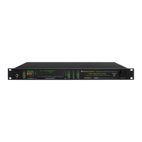
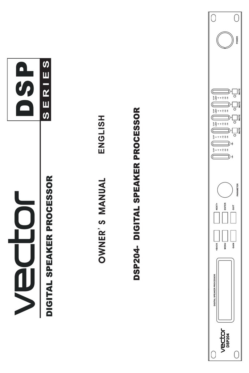
4.1 Front Panel
1.
LCD PANEL: displays the menu and the parameters configured in the equipment
2.
BACK/NEXT: used to scroll through the menus
3.
MENU: provides access to the equipment's configurations, limiters, crossovers, etc.
4.
GAIN: gain adjustment button
5.
QUIT: button to leave the menu
6.
ENTER: confirmation button
7.
PARAMETER: button to adjust and change
8.
INPUT/OUTPUT LED: LED indicator of input and output signal
9.
MUTE: button to mute the outputs
10.POWER: on/off button
4.2 Rear Panel
Figure
1. EXTRA FUSE
2.
POWER PLUG, AUTOMATIC Voltage Selector
3. PC LINK CONNECTOR
4. SIGNAL OUTPUTS
XLR cable connection
used
From 1 to 6:
Figure 1
LCD PANEL: displays the menu and the parameters configured in the equipment
BACK/NEXT: used to scroll through the menus
MENU: provides access to the equipment's configurations, limiters, crossovers, etc.
GAIN: gain adjustment button
QUIT: button to leave the menu
ENTER: confirmation button
PARAMETER: button to adjust and change
the parameters
INPUT/OUTPUT LED: LED indicator of input and output signal
MUTE: button to mute the outputs
POWER PLUG, AUTOMATIC Voltage Selector
used
5
LCD PANEL: displays the menu and the parameters configured in the equipment
MENU: provides access to the equipment's configurations, limiters, crossovers, etc.

6
Channels 1 and 4 for sub-woofer and bass frequencies
Channels 2 and 5 for mid-bass and medium frequencies
Channels 3 and 6 for mid-high and high frequencies
4. SIGNAL INPUTS
XLR cable connection used
A and B
5 Operation
The DT2006S receives a configuration for the Selenium's previous usages. This
configuration merges performance and the system's excellent intelligibility. Therefore, for the
user to control each track of the SLI-Ribbon265 system, then the signal's volume (intensity)
needs to be controlled at the sound table.
The configurations preset by Selenium can be changed, however, to meet the tastes of the
user or to adapt it to a specific type of application to which the system may be submitted.
Selenium recommends that before changing any of the DT2006S preset configurations that the
user contact our technical support team to clarify the implications of these changes to the
system's performance.
CAUTION, the DT2006S is configured to work at maximum power. This means that if you
turn on your table's sound system or mixer and your amplifiers are also at their maximum, the
sound will begin playing at maximum volume.
TIP: before turning on the system, set the sound table or mixer's volume at its minimum
and go turning up the volume carefully to the desired level or limit of your amplifiers.
The access to the DT2006S configuration commands is blocked by password. The only
commands accepted are the MUTE buttons.
If you need to make a change, contact Selenium to provide you with this password.
Any change to the configuration parameters should be done with extreme caution because
they can affect both the quality of the sound system as well as its durability, nullifying the
warranty against defects.
The buttons on the front panel of the DT2006S are used to change the parameters defined
by Selenium.
The sequence to do so is shown in the next chapter.

5.1 Re-configuration
5.1.1- Sub-
menu Xover (crossover)
A) Push the button “Menu” and then BACK/NEXT and ENTER to access
the Sub-menu
XOVER. This sub
B) LOAD A XOVER: loads a crossover stored in the memory.
C) DESIGN A XOVER: configures the type of crossover, the input channel
control, and the stereo connection.
D) STORE A XOVER: memorizes all the
certain memory position. There are 10 positions available. The name of each
memory position can have up to 16 characters.
E) ERASE A XOVER: erases a memory position.
2-Sub-menu SECURITY
Push the “Menu” button and then BACK/
menu SECURITY. This sub
functions in the processor.
There are 4 security levels:
CHANGE ONLY, where the parameters can be accessed, but not be changed.
The MUTE buttons a
CHANGE+VIEW, where the parameters cannot be accessed nor changed. The
MUTE buttons are operational.
CHANGES+MUTES, where the parameters can be accessed but not changed.
The MUTE buttons are not operational.
EVERYTHING, where the parameters
and the MUTE buttons are not operational.
A) After the security level is selected, press ENTER.
Use the buttons BACK and NEXT to move the cursor and turn the parameters
button to select the character. Once the passw
menu Xover (crossover)
A) Push the button “Menu” and then BACK/NEXT and ENTER to access
XOVER. This sub
-
menu includes the following commands:
B) LOAD A XOVER: loads a crossover stored in the memory.
C) DESIGN A XOVER: configures the type of crossover, the input channel
control, and the stereo connection.
D) STORE A XOVER: memorizes all the
adjustments of a crossover in a
certain memory position. There are 10 positions available. The name of each
memory position can have up to 16 characters.
E) ERASE A XOVER: erases a memory position.
Push the “Menu” button and then BACK/
NEXT and ENTER to access the Sub
menu SECURITY. This sub
-
menu includes functions to block the access to other
functions in the processor.
There are 4 security levels:
CHANGE ONLY, where the parameters can be accessed, but not be changed.
The MUTE buttons a
re operational.
CHANGE+VIEW, where the parameters cannot be accessed nor changed. The
MUTE buttons are operational.
CHANGES+MUTES, where the parameters can be accessed but not changed.
The MUTE buttons are not operational.
EVERYTHING, where the parameters
cannot be accessed, cannot be changed,
and the MUTE buttons are not operational.
A) After the security level is selected, press ENTER.
Use the buttons BACK and NEXT to move the cursor and turn the parameters
button to select the character. Once the passw
ord is correct, press ENTER.
7
A) Push the button “Menu” and then BACK/NEXT and ENTER to access
menu includes the following commands:
B) LOAD A XOVER: loads a crossover stored in the memory.
C) DESIGN A XOVER: configures the type of crossover, the input channel
adjustments of a crossover in a
certain memory position. There are 10 positions available. The name of each
NEXT and ENTER to access the Sub
-
menu includes functions to block the access to other
CHANGE ONLY, where the parameters can be accessed, but not be changed.
CHANGE+VIEW, where the parameters cannot be accessed nor changed. The
CHANGES+MUTES, where the parameters can be accessed but not changed.
cannot be accessed, cannot be changed,
Use the buttons BACK and NEXT to move the cursor and turn the parameters
ord is correct, press ENTER.

B) Repeat procedure A in order to confirm the password and the system will be
blocked. If the password is not the same, the operation will be canceled.
C) The correct password must be given and press ENTER to unblock the sys
3-Sub-menu SYSTEM
Push the “Menu” button and then BACK/NEXT and ENTER to access the Sub
menu SYSTEM.
A)
The first option is INPUT OPTION that makes it possible to link the input
channels (A and B). With this option enabled, every change made to chann
A will be automatically applied to channel B.
B)
The second option is WAKE UP. This option makes it possible to choose the
signal's behavior as soon as the DT2006S is turned on. FADE
possible to gradually increase the signal's volume. MUTE HOLD
DT2006S with the MUTE buttons on.
C)
The option DELAY TIME/DISTANCE makes it possible to choose the unit in
which the delay time will be shown (time in ms, meters or feet).
D)
The option INTERFACE makes it possible to adjust the baud rate and the
addressing code (ID). The baud rate options are 2400, 4800, 9600, 19200,
and 38400. The ID can be set between 1 and 32.
4- Adjust the PARAMETERS
To adjust the parameters of a crossover, press the button GAIN and use buttons
BACK/NEXT and ENTER to scr
adjust the parameter value.
1- INPUT GAIN
–
2-
OUTPUT GAIN
3- POLARITY –
B) Repeat procedure A in order to confirm the password and the system will be
blocked. If the password is not the same, the operation will be canceled.
C) The correct password must be given and press ENTER to unblock the sys
Push the “Menu” button and then BACK/NEXT and ENTER to access the Sub
The first option is INPUT OPTION that makes it possible to link the input
channels (A and B). With this option enabled, every change made to chann
A will be automatically applied to channel B.
The second option is WAKE UP. This option makes it possible to choose the
signal's behavior as soon as the DT2006S is turned on. FADE
possible to gradually increase the signal's volume. MUTE HOLD
DT2006S with the MUTE buttons on.
The option DELAY TIME/DISTANCE makes it possible to choose the unit in
which the delay time will be shown (time in ms, meters or feet).
The option INTERFACE makes it possible to adjust the baud rate and the
addressing code (ID). The baud rate options are 2400, 4800, 9600, 19200,
and 38400. The ID can be set between 1 and 32.
To adjust the parameters of a crossover, press the button GAIN and use buttons
BACK/NEXT and ENTER to scr
oll the menus and rotate the PARAMETERS button in order to
–
this parameter accepts values from -
40dB to +6dB.
OUTPUT GAIN
– this parameter accepts values from
-
output channel polarity selected (+ or -)
8
B) Repeat procedure A in order to confirm the password and the system will be
blocked. If the password is not the same, the operation will be canceled.
C) The correct password must be given and press ENTER to unblock the sys
tem.
Push the “Menu” button and then BACK/NEXT and ENTER to access the Sub
-
The first option is INPUT OPTION that makes it possible to link the input
channels (A and B). With this option enabled, every change made to chann
el
The second option is WAKE UP. This option makes it possible to choose the
signal's behavior as soon as the DT2006S is turned on. FADE
-IN makes it
possible to gradually increase the signal's volume. MUTE HOLD
starts up the
The option DELAY TIME/DISTANCE makes it possible to choose the unit in
which the delay time will be shown (time in ms, meters or feet).
The option INTERFACE makes it possible to adjust the baud rate and the
addressing code (ID). The baud rate options are 2400, 4800, 9600, 19200,
To adjust the parameters of a crossover, press the button GAIN and use buttons
oll the menus and rotate the PARAMETERS button in order to
40dB to +6dB.
-
40dB to +6dB.

4- DELAY –
a delay on the output channel selected (from 0 to 7 ms in intervals of
0.5 ms)
5- HPF&LPF –
adjusts the parameters of the High
Pass Filters (LPF).
The symbol
PARAMETER button. Press the same button to select another parameter. The
frequency intervals permitted for each one are as follows:
LPF 35 Hz to 22 kHz and HPF from 10Hz to 16kHz.
6- PEQ –
Parametric Equalizers: Up to 5 PEQs are allowed per output channel.
These filters may be of the following types:
HiShelf, LoShelf, and PEQ, as indicated on the DT2006S panel by "{", "}", and
.
The "=" symbol indicates
Move the cursor to the Q adjust and turn the PARAMETER dial to select the
Hishelf and Loshelf type filters.
The amounts permitted for each parameter are as follows:
Frequency: 20Hz ~ 20kHz
Q: 0.5 to 10
Gain: 12dB to +12d
HiShelf: 1kHz to 20kHz
LoShelf: 20Hz to 1kHz
7- LIMITERS –
have the following parameters:
LEVEL –
dB threshold
HOLD –
Time that the limiter continues active after the Threshold is up (ms)
a delay on the output channel selected (from 0 to 7 ms in intervals of
adjusts the parameters of the High
-
Pass Filters (HPF) and Low
Pass Filters (LPF).
indicates the parameter that will be changed by rotating the
PARAMETER button. Press the same button to select another parameter. The
frequency intervals permitted for each one are as follows:
LPF 35 Hz to 22 kHz and HPF from 10Hz to 16kHz.
Parametric Equalizers: Up to 5 PEQs are allowed per output channel.
These filters may be of the following types:
HiShelf, LoShelf, and PEQ, as indicated on the DT2006S panel by "{", "}", and
The "=" symbol indicates
that the filter is switched off.
Move the cursor to the Q adjust and turn the PARAMETER dial to select the
Hishelf and Loshelf type filters.
The amounts permitted for each parameter are as follows:
Frequency: 20Hz ~ 20kHz
Gain: 12dB to +12d
B
HiShelf: 1kHz to 20kHz
LoShelf: 20Hz to 1kHz
have the following parameters:
dB threshold
Time that the limiter continues active after the Threshold is up (ms)
9
a delay on the output channel selected (from 0 to 7 ms in intervals of
Pass Filters (HPF) and Low
-
indicates the parameter that will be changed by rotating the
PARAMETER button. Press the same button to select another parameter. The
Parametric Equalizers: Up to 5 PEQs are allowed per output channel.
HiShelf, LoShelf, and PEQ, as indicated on the DT2006S panel by "{", "}", and
Move the cursor to the Q adjust and turn the PARAMETER dial to select the
The amounts permitted for each parameter are as follows:
Time that the limiter continues active after the Threshold is up (ms)

10
ATTACK – Time that the limiter takes to take action after the signal exceeds
the Threshold (ms)
DECAY – Time for the limiter to cease taking action after the HOLD time. The
releasing of the signal in the decay is progressive and this time is the limit for
the signal to return to the level previous to the limiter's actions.
The amounts permitted for each parameter are as follows:
LEVEL – from -20dB to +15dB
ATTACK – from 1 to 100ms
HOLD – from 0 to 1000ms
DECAY – from 0 to 1000ms
8- To change the channel's name, turn the PARAMETER button until locating
the name to be selected.
9- Input Signal – makes it possible to view the channel's signal source. This field
cannot be changed.
Table of contents
