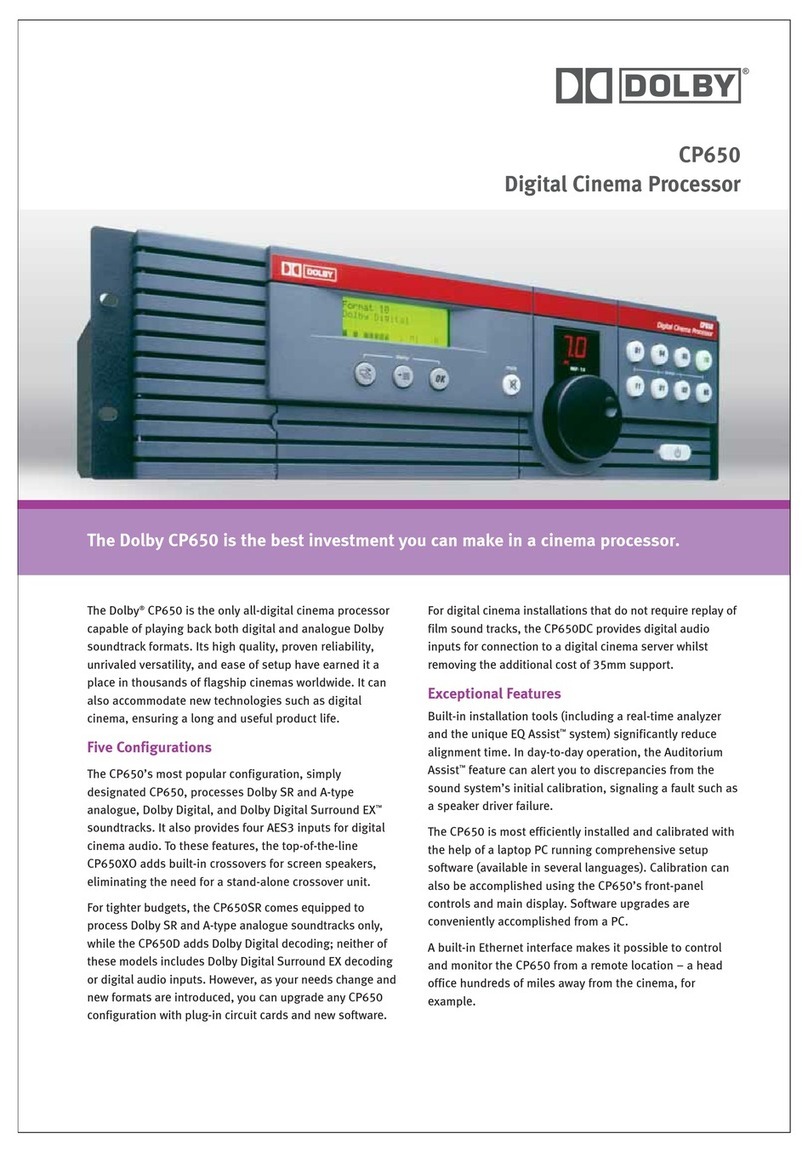
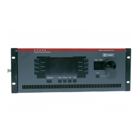
Dolby Laboratories CP650 User manual

Model CP650
Digital Cinema Sound
Processor
Installation Manual
Issue 2 Part No. 91569

CP650 Installation Manual
ii
Dolby Laboratories, Inc.
Corporate Headquarters
Dolby Laboratories, Inc.
100 Potrero Avenue
San Francisco, CA 94103-4813
Telephone 415-558-0200
Facsimile 415-863-1373
www.dolby.com
European Headquarters
Dolby Laboratories, Inc.
Wootton Bassett
Wiltshire, SN4 8QJ, England
Telephone (44) 1793-842100
Facsimile (44) 1793-842101
DISCLAIMER OF WARRANTIES: Equipment manufactured by Dolby Laboratories is warranted against defects
in materials and workmanship for a period of one year from the date of purchase. All warranties, conditions or other
terms implied by statute are excluded to the fullest extent allowed by law.
LIMITATION OF LIABILITY: It is understood and agreed that Dolby Laboratories' liability whether in contract,
in tort, under any warranty, in negligence or otherwise shall not exceed the cost of repair or replacement of the
defective components and under no circumstances shall Dolby Laboratories be liable for incidental, special, direct,
indirect or consequential damages (including but not limited to damage to software or recorded audio or visual
material), or loss of use, revenue or profit even if Dolby Laboratories or its agents have been advised, orally or in
writing, of the possibility of such damages.
Dolby, EQ Assist, Surround EX, and the double-D symbol are trademarks of Dolby Laboratories. All other trademarks remain
the property of their respective owners.
(c)2001DolbyLaboratories,Inc. All rights reserved.Issue 2
S00/13092/13640
Part No. 91569
Software Version 1.2.x.x

CP650 Installation Manual
iii
Table of Contents
List of Figures............................................................................................................... vi
List of Tables ................................................................................................................vii
Operating System Software History...........................................................................viii
Chapter 1 Introduction
1.1 About the Dolby CP650 Cinema Processor .............................................1-1
1.2 Hardware Configurations Available.........................................................1-2
1.3 Accessories...............................................................................................1-3
1.4 List of Catalog Numbers Used .................................................................1-3
1.5 Specifications............................................................................................1-3
1.6 About Dolby Digital Surround EX...........................................................1-5
1.7 List of Formats Available.........................................................................1-6
1.8 How to Identify Types of Soundtracks.....................................................1-8
1.9 Regulatory Notices...................................................................................1-9
Chapter 2 Installation
2.1 Replacing an Existing Sound System.......................................................2-1
2.1.1 Before playing the film:..............................................................2-1
2.1.2 While playing the film:...............................................................2-1
2.1.3 Disconnect the old system...........................................................2-2
2.2 Check Fuse and Bypass Mains Voltage Selector .....................................2-2
2.3 Mount the CP650......................................................................................2-3
2.4 Connect the CP650...................................................................................2-4
2.4.1 Motor Start Relays......................................................................2-4
2.4.2 Remote Controls .........................................................................2-4
2.4.3 Solar Cell Reader Boards............................................................2-5
2.4.4 Analog Nonsync Sources............................................................2-7
2.4.5 Digital Audio Sources.................................................................2-8
2.5 Exploded View and Board Locations.....................................................2-11
Wiring Diagram- Input and Control...................................................................2-12
Wiring Diagram- Audio Ouputs.........................................................................2-13
System Signal Flow Chart..................................................................................2-14
Chapter 3 Front Panel and Alignment Overview
3.1 The CP650 Front Panel.............................................................................3-1
3.2 The Setup Control Panel...........................................................................3-5
3.3 Power Supply Voltage Test Points...........................................................3-6
3.4 Aligning the B-Chain and A-Chain..........................................................3-7

CP650 Installation Manual
iv
Chapter 4 B-Chain Alignment
4.1 Check Theatre Equipment ........................................................................4-1
4.2 Microphone Placement.............................................................................4-2
4.3 Initial Setup...............................................................................................4-3
4.4 SPL (Sound Pressure Level) Calibration..................................................4-4
4.5 Initial Output Level Calibration ...............................................................4-5
4.5.1 Main Channels ............................................................................4-5
4.5.2 Subwoofer Channel.....................................................................4-6
4.6 Room Equalization...................................................................................4-7
4.6.1 Setting Coarse (Bulk) EQ ...........................................................4-7
4.6.2 Setting Fine EQ (1/3 octave).......................................................4-8
4.6.3 The EQ Assist Feature ..............................................................4-10
4.6.4 Setting Subwoofer Channel EQ................................................4-11
4.7 Final Output Level Calibration...............................................................4-13
4.8 Final Sound Check: Rotating Pink Noise...............................................4-16
Chapter 5 A-Chain Alignment
5.1 Overview ..................................................................................................5-1
5.2 Reverse-Scan Checkup: Projector............................................................5-2
5.3 Analog Optical Alignment: Projector.......................................................5-2
5.4 Dolby Level Set........................................................................................5-4
5.5 Film Path Alignment Check.....................................................................5-6
5.6 Cell Alignment Check..............................................................................5-7
5.7 Cell Wiring Check....................................................................................5-8
5.8 Azimuth Check.........................................................................................5-8
5.9 Focus Check .............................................................................................5-9
5.10 Optical HF Equalization (Slit-Loss EQ).................................................5-10
Chapter 6 Digital Soundheads
6.1 Mechanical Alignment .............................................................................6-1
6.2 Adjustment with Oscilloscope..................................................................6-2
6.3 Focus Adjustment.....................................................................................6-2
6.4 LED Brightness Confirmation and Adjustment .......................................6-3
Inboard Digital Readers............................................................................6-3
Chapter 7 Final Adjustments
7.1 Bypass Level Adjustment.........................................................................7-1
7.2 Setting Optical Surround Delay................................................................7-1
7.3 Setting Digital Surround Delay................................................................7-3
7.4 Setting Dolby Digital Reader Delay.........................................................7-4
7.5 Nonsync Level Adjustment......................................................................7-6
7.6 Mono Level Trim and EQ Adjustment.....................................................7-7
7.7 Preset Fader Levels...................................................................................7-8

CP650 Installation Manual
v
7.8 Assigning User Button Formats ...............................................................7-9
7.9 Assigning NS Button Format ...................................................................7-9
7.10 Reversion Mode......................................................................................7-10
7.11 Auto Surround EX Disable.....................................................................7-10
7.12 Noise Gating...........................................................................................7-11
7.13 Clock Set ................................................................................................7-11
7.14 Date set...................................................................................................7-12
7.15 Mute Fade Time Adjustment..................................................................7-12
Chapter 8 Accessories
8.1 Introduction ..............................................................................................8-1
8.2 Cat. No. 779 Remote Control Installation................................................8-2
8.3 Cat. No. 771 Remote Fader Installation...................................................8-6
Chapter 9 Maintenance and Troubleshooting
9.1 Print Cleanliness.......................................................................................9-1
9.2 Digital Soundhead Maintenance...............................................................9-1
9.2.1 Replacing the Cat. No. 701 LED Assembly ...............................9-2
9.2.2 Replacing the Cat. No. 700 Exciter Lamp ..................................9-5
9.3 CP650 Troubleshooting............................................................................9-6
9.3.1 Power Supply Voltage Ranges....................................................9-6
9.3.2 Exploded View and Board Locations .........................................9-7
9.3.3 Troubleshooting Chart ................................................................9-7
Power Supply Wiring Diagrams.........................................................................9-17
Cat. No. 701/700 Exploded Views.....................................................................9-19
Appendix A Software Operations
A.1 Updating CP650 Software.......................................................................A-1
A.2 Transferring Settings Between Two CP650s...........................................A-2
Appendix B Back Panel Connectors
Appendix C Optical Surround Level Trim
Appendix D Format Descriptions
D.1 Channel Definitions.................................................................................D-1
D.2 Format Definitions...................................................................................D-2
Appendix E External Control of CP650
E.1 Control Via RS-232 Serial Data Port ......................................................E-1
E.2 Control Via Remotes Connector..............................................................E-4
Appendix F Setup and User Menus
F.1 CP650 Setup Menu.................................................................................. F-1
F.2 CP650 User Menu ................................................................................... F-3

CP650 Installation Manual
vi
List of Figures
Figure 1–1 Surround Speaker/Amplifier Switching for 5.1 and Surround EX Modes ................1-6
Figure 1–2 Photograph of Film Soundtracks................................................................................1-8
Figure 1–3 Film Soundtrack Identification ..................................................................................1-8
Figure 2–1 Main Fuse Assembly..................................................................................................2-2
Figure 2–2 Star Washers and Rack Mounting Screws.................................................................2-3
Figure 2–3 Cell Preamp Wiring Using Two 3-Conductor Shielded (screened) Cables...............2-6
Figure 2–4 Cell Preamp Wiring Using One 5- or 6-Conductor Shielded (screened) Cable ........2-6
Figure 2–5 Cell Preamp Wiring Using Two 2-Conductor Shielded (screened) Cable ................2-7
Figure 2–6 Cell Preamp Wiring Using One 4-Conductor Shielded (screened) Cable.................2-7
Figure 2–7 Cat. No. 794 AES/EBU and S/PDIF Jumper Selections............................................2-8
Figure 2–8 Model CP650 Exploded View .................................................................................2-11
Figure 3–1 Front Panel Controls ..................................................................................................3-1
Figure 3–2 Front Panel Display....................................................................................................3-2
Figure 3–3 Fader Characteristic ...................................................................................................3-3
Figure 3–4 CP650 Operation and Setup Menu Control Buttons..................................................3-4
Figure 3–5 Setup Control Panel....................................................................................................3-5
Figure 3–6 Power Supply Voltage Test Points.............................................................................3-6
Figure 4–1 EQ Microphone Placement ........................................................................................4-2
Figure 4–2 EQ Assist Operating Range .....................................................................................4-10
Figure 6–1 Digital Soundhead Adjustments.................................................................................6-1
Figure 6–2 Digital Video Oscilloscope Image – Focus Adjustment............................................6-3
Figure 6–3 Cat. No. 701 LED Brightness Adjustment.................................................................6-3
Figure 8–1 Cat. No. 779 Remote Control Functions....................................................................8-2
Figure 8–2 Location to Drill Wiring Hole on Remote Control....................................................8-3
Figure 8–3 Remote Control Circuit Board Connector..................................................................8-3
Figure 8–4 Remote Control SW1 Address Switch Location........................................................8-4
Figure 8–5 Connection of Remotes to the CP650........................................................................8-5
Figure 9–1 Digital/Analog Track Wear........................................................................................9-1
Figure 9–2 Cat. No. 701 LED Assembly Mounting Screws ........................................................9-2
Figure 9–3 Cat. No. 701 LED Assembly Wiring.........................................................................9-2
Figure 9–4 Cat. No. 701 LED Assembly Initial Gap Setting.......................................................9-2
Figure 9–5 Scope Display of CP650 Video Test Point Signal.....................................................9-4
Figure 9–6 Adjust Cat. No. 701 LED Assembly for Optimum Video Signal..............................9-4
Figure 9–7 Cat. No. 701 LED Drive Current Setting...................................................................9-4
Figure 9–8 Cat. No. 700 Digital Soundhead Exciter Lamp Replacement....................................9-5
Figure 9–9 Power Supply Voltage Test Points.............................................................................9-6
Figure 9–10 Model CP650 Exploded View .................................................................................9-7

CP650 Installation Manual
vii
List of Tables
Table 1–1 Formats Supported by the CP650................................................................................1-6
Table 2–1 Solar Cell Preamp Board Connectors..........................................................................2-5
Table 2–2 Examples of AES/EBU ↔
↔↔
↔S/PDIF Adapters Available...........................................2-10
Table 7–1 Surround Delays Based on Theatre Dimensions in Feet.............................................7-3
Table 7–2 Surround Delays Based on Theatre Dimensions in Meters.........................................7-4
Table 7–3 Typical Delay Settings for Dolby Digital Readers......................................................7-5
Table 7–4 Typical Delay Settings for Built-in Digital Readers ...................................................7-5
Table 9–1 Main Power Supply Voltage Ranges...........................................................................9-6
Table 9–2 Bypass Power Supply Voltage Ranges........................................................................9-6
Table B–1 Main Audio Output Connector Pinout.......................................................................B-1
Table B–2 Option Card I/O Connector with Cat. No. 794 Installed...........................................B-2
Table B–3 Dolby Digital Reader Input Connector Pinout ..........................................................B-3
Table B–4 Motor Start Connector Pinout....................................................................................B-4
Table B–5 Optical Input Connector Pinout.................................................................................B-4
Table B–6 MIC Input Connector Pinout .....................................................................................B-4
Table B–7 Mic Mux Connector...................................................................................................B-5
Table B–8 Remote Unit and Remote Fader Connector Pinout ...................................................B-5
Table B–9 Six-Channel Analog Input Connector Pinout............................................................B-6
Table B–10 Automation I/O Connector Pinout...........................................................................B-7
Table B–11 Automation I/O Connector Pins Used for Noise Gating .........................................B-8
Table B–12 Serial Data (RS-232) Connector Pinout...................................................................B-8
Table D–1 Channel Definitions...................................................................................................D-1
Table D–1 Format Characteristics Chart.....................................................................................D-8

CP650 Installation Manual
viii
CP650 Operating System Software History
V1.0.4.4
•First product shipments.
•Covered in installation manual issue 1.
V1.1.3.0
•Added support for Cat. No. 794 card: Dolby Digital Surround EX decoder and
AES/EBU input for stereo PCM or Dolby Digital bitstreams from consumer
products.
•Covered in installation manual addendum, part number 91743.
V1.1.5.0
•Added support for Cat. No. 779 remote control unit and Cat. No. 771 remote
fader unit. Covered in remotes installation manual, part number 91733.
V1.1.7.0
•Added support for formats 92 and 93: Dolby SR input selections. Covered in
format definitions document on CD-ROM.
V1.2.x.y (X, Y may be any number)
•Added support for Auto Dolby Digital Surround EX switching, external
control via the RS-232 serial data port, and the rotating pink noise feature.
•These features, along with the EQ Assist®function, plus all of the above
updates are covered in this installation manual.

CP650 Installation Manual
1-1
Chapter 1
Introduction
1.1 About the Dolby CP650 Cinema Processor
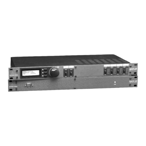
The Dolby CP650 is a self-contained, all-digital cinema processor capable of
supporting Dolby Digital, Dolby Digital Surround EX, Dolby SR, Dolby A-type, and
Academy mono film sound playback.
The CP650 provides inputs for two projector soundheads (both analog and digital), an
external six-channel processor, two nonsync sources, and a PA microphone. Its audio
outputs are balanced, with a multipin connector configured to the THX standard. The
CP650 is the first cinema processor to incorporate an Ethernet connection, enabling
theatre personnel to monitor the unit’s functions remotely from a PC.
For decoding analog soundtracks, the CP650’s state-of-the art design incorporates the
only digital implementations of Dolby A-type and Dolby SR decoding to meet Dolby
Laboratories’ own rigorous standards. Reductions in the cost of powerful DSP
circuitry have made it possible for the first time to replace the analog circuitry
previously necessary for the accurate reproduction of A-type and SR soundtracks.
An easy-to-read LCD screen, plus simple front-panel format selection and control
buttons make it easy to install, operate, and maintain the CP650. Installation is further
simplified by built-in test instrumentation that includes a real-time analyzer. Third-
octave equalization, plus bass and treble trim controls, are provided for up to seven
channels (Left, Center, Right, Left Surround, Right Surround, Back Surround Left,
and Back Surround Right). A digital parametric equalizer is provided for subwoofer
equalization.
Easily-programmed internal software manages most existing or likely future formats.
While an external PC is not required for setup, a full-featured software package is
available in a variety of languages to facilitate the setup process. A serial connector
for a PC, an input for a calibration microphone multiplexer, and a variety of test
points are all accessible behind an access door on the front panel. Built-in diagnostic
software runs automatically whenever the CP650 is turned on.
Calibration settings for a given theatre can be stored on a PC, and, if necessary,
transferred directly to another CP650, or other modules, minimizing the need for
additional calibration after repairs. As improvements to the CP650 digital control and
processing software are developed, the latest revisions will be downloadable from a
PC to the CP650. Updates to the digital processing used for Dolby Digital
soundtracks are included from time to time on Dolby Digital release prints, and
download automatically into the CP650 the first time such a print is played in the
cinema.

CP650 Installation Manual Introduction
1-2
The standard Model CP650 includes a Cat. No. 794 plug-in module featuring Dolby
Digital Surround EX decoding capability plus an AES/EBU digital input
accommodating stereo PCM audio and Dolby Digital (consumer) bitstreams.
Options available for the CP650 include a remote fader (Cat. No. 771), and a remote
unit duplicating many of the CP650 front panel controls (Cat. No. 779).
1.2 Hardware Configurations Available
The CP650 is available in three versions:
Model CP650
•Dolby Digital soundtrack decoding capability
•Dolby A-type and SR analog soundtrack decoding capability
•Dolby Digital Surround EX decoding and AES/EBU digital input
•Six-channel analog input
Model CP650D
•Dolby Digital soundtrack decoding capability
•Dolby A-type and SR analog soundtrack decoding capability
•Six-channel analog input
•Upgradable to Dolby Digital Surround EX decoding and AES/EBU digital
input by installing upgrade kit UEX/650, which includes a Cat. No. 794 plug-
in circuit board.
Model CP650SR
•Dolby A-type and SR analog soundtrack decoding capability
•Six-channel analog input
•Upgradable to Dolby Digital soundtrack decoding by adding upgrade kit
UD/650, which includes a Cat. No. 773 plug-in circuit board.
•Upgradable to Dolby Digital Surround EX decoding and AES/EBU digital
input by adding upgrade kits UD/650 and UEX/650, which includes a
Cat. No. 794 plug-in circuit board.

CP650 Installation Manual Introduction
1-3
1.3 Accessories
•Cat. No. 771 Remote Fader
•Cat. No. 779 Remote Control Unit
•Upgrade kit UD/650, which includes the Cat. No. 773 circuit board
•Upgrade kit UEX/650, which includes the Cat. No. 794 circuit board
1.4 List of Catalog Numbers Used
Cat. No. 771 Remote Fader
Cat. No. 772 Analog I/O and Bypass Circuit Board
Cat. No. 773 Dolby Digital Film Decoder Circuit Board
Cat. No. 774 System Controller Circuit Board
Cat. No. 775 Backplane Board
Cat. No. 776 Power Supply Assembly
Cat. No. 777 Front Panel Circuit Board
Cat. No. 779 Remote Control Unit
Cat. No. 792 Bypass Power Regulator Circuit Board
Cat. No. 794 Dolby Digital Surround EX Decoder with Digital AES/EBU Input
Board
Cat. No. 797 Flash memory module, part of the Cat. No. 774 board
1.5 Specifications
Signal Inputs
Optical: Balanced inputs for two projectors with stereo solar cells or analog LED
readers. Digitally controlled gain and digital slit loss EQ. Power available for external
cell preamp circuits. 9-pin D-connectors.
Digital film reader: Inputs for two Dolby digital soundheads. 25-pin D-connectors.
Nonsync: Two stereo inputs, 21 kΩ, sensitivity: 0.2–4V (NS 1),
0.06–1.5V (NS 2). RCA-type phono connectors.
Six-channel analog input: For external digital processor,10 kΩ(L, R),
27 kΩ(C, Ls, Rs, SW), 300 mV operating level. 25-pin D-connector.
Microphone: Balanced input for PA mic or B-chain alignment mic
(or multiplexer), 15 V phantom power switchable via front-panel DIP switch.
Rear-panel XLR and front-panel 9-pin D-connector.
AES/EBU digital input: Accommodates stereo PCM audio at 48, 44.1, or 32 ksps.
Also accepts Dolby Digital or Dolby E bitstreams. Input via 25-pin D-connector,
110Ω±20 %, balanced.
Main Eight-Channel Signal Outputs
Balanced, output impedance: 100Ω(load >600Ω).
Maximum level: +26 dBu (balanced loads), +20 dBu (unbalanced).
Typical operating level: –10 dBu with fader set to 7.
Operating range: 20–780 mV.

CP650 Installation Manual Introduction
1-4
Other Connections
Cat. No. 779 remote control unit and Cat. No. 771 remote fader connector (terminals
for stripped wires).
Connectors (front and rear) for external PC control and setup, RS-232C
(9-pin D-connector).
Hearing impaired output: center-weighted sum of L, R, and C, output
impedance 100Ω, output level 200 mV fixed, unbalanced (RCA-type phono
connector).
Automation connector for controlling and indicating format, fader select, and mute.
Interface similar to Model CP65.
Connector for Ethernet link (future use, RJ-45 connector).
Dolby Decoding
5.1 channels, Dolby Digital, and Dolby Digital Surround EX
Four channels, Dolby A-type
Two channels, Dolby SR
Dolby Pro Logic
Loudspeaker Equalization
L, C, R, Ls, Rs, Bsl, Bsr: 27-band digital 1/3-octave, plus bass and treble control.
SW: digital parametric with 12 dB cut capability.
Distortion
Typically 0.005% in Dolby SR mode (output –10 dBu, input 10 dB over Dolby level).
Dynamic Range
Typically 99 dB with fader set to 7.
Dimensions and Weight
3-U rack-mount chassis. Faceplate: 137 mm(H) x 448 mm(W) (5 3/8" x 17 5/8").
Maximum projection behind equipment rack rail: 365 mm (14 3/8").
Maximum projection in front of mounting plate: 38 mm (1 1/2").
Weight: 10.4 kg (23 lbs.).
Shipping Weight: 13.6 kg (30 lbs.).
Power Requirements
Main supply: 100–120 and 200–240 VAC, 50–60 Hz, 100 W max.
Built-in bypass power supply.
Unit designed to operate from a centrally switched power source.

CP650 Installation Manual Introduction
1-5
1.6 About Dolby Digital Surround EX
Dolby Digital Surround EX adds a third surround channel to digital film sound, a
concept first envisioned by sound designers at Lucasfilm’s Skywalker Sound post-
production facility. Jointly developed by Dolby Laboratories and Lucasfilm THX,
Dolby Digital Surround EX gives sound mixers a new level of creative freedom.
Dolby Digital Surround EX is fully compatible with all current 5.1 digital sound
formats and theatre systems. Prints that use it play normally with current systems, and
provide the extra surround channel when played using a CP650 cinema processor
equipped with the Cat. No. 794 board, or earlier Dolby cinema processors equipped
with the Dolby model SA10 adapter.
It has long been known that a center screen channel is necessary to ensure the precise
localization of front sounds for all viewers, including those seated to the sides of the
theatre. Dolby Digital Surround EX brings similar benefits to the surround
soundfield. With Surround EX, a back surround channel is reproduced by the speaker
array at the back of the theatre, while left and right surround is reproduced by the side
arrays. This means that sounds can now be positioned behind the audience, opening
the door to exciting new effects, such as true 360° pans.
The back surround channel also makes front-to-back and back-to-front transitions
more realistic. Flyovers really seem to pass overhead, rather than down the sides of
the theatre. Even ambient sound reproduction is improved, being less affected by the
width of the theatre. Equally important, the new back surround channel assures that
even viewers seated close to the left or right of the theatre experience the total
surround ambience intended by the filmmaker.
The UEX/650 kit upgrades the CP650D 5.1-channel digital cinema sound processor
to three surround channels that can play digital prints prepared with the Dolby Digital
Surround EX process. The installation requires wiring the surround speakers into left,
back (split into two groups), and right. Two power amplifier channels are required
for powering the two groups of back surround channel speakers. The figures on the
next page show the surround signal distribution for conventional 5.1-channel
surround and for Dolby Digital Surround EX format.
Auto Surround EX
On Dolby Digital soundtracks that contain a data bit signifying Surround EX
encoding, the CP650 will automatically switch to Dolby Digital Surround EX
decoding (operating software version 1.2 and above).

CP650 Installation Manual Introduction
1-6
Left surround
Back surround left
Right surround
Back surround right
Dolby Digital
5.1 mode
Surround
amplifiers
Dolby CP650 Ls
Bsl
Bsr
10
Rs
Ls
Rs
Ls
Bsl
Bsr
Rs
Left surround
Back surround left
Right surround
Back surround right
Dolby Digital
Surround EX mode
Surround
amplifiers
Dolby CP650 Ls
Bsl
Bsr
U1
Rs
Ls
Rs
Ls
Bsl
Bsr
Rs
Bs
Figure 1–1 Surround Speaker/Amplifier Switching for 5.1 and Surround EX Modes
1.7 List of Formats Available
The formats supported by the CP650 are listed below. See Appendix D for complete
definitions of each format.
Table 1–1 Formats Supported by the CP650
Format Description
01 Academy Mono Optical
Short name: Mono
04 Dolby A-type Optical
Short name: Dolby A-type
05 Dolby SR Optical
Short name: Dolby SR
10 Dolby Digital Film
Short name: Dolby Digital
11 External 6-Channel

CP650 Installation Manual Introduction
1-7
Table 1–1, continued Formats Supported by the CP650
Format Description
13 Dolby Digital Surround EX Film
Short name: Surround EX
20 35 mm Magnetic, L, C, R 3-Channel
Short name: 3-Channel Mag
22 35 mm Magnetic, 4-Channel
Short name: 4-Channel Mag
42 70 mm Dolby A-type Mag. Mono
surround
Short name: 70 mm Dolby A-type
60 Nonsync 1
61 Nonsync 2
64 Public Address Center Channel
Short name: Public Address, C
65 Public Address Surround Channels
Short name: Public Address LsRs
66 Test Tone 320 Hz
70 Video PA Nonsync 1
Short name: Video PA (NS1)
71 Video mono Nonsync 1
Short name: Video Mono (NS1)
73 Video LCR Nonsync 1
Short name: Video LCR (NS1)
74 Video Pro Logic no SW Nonsync 1
Short name: Vid Pro Logic no SW
75 Video Pro Logic with SW Nonsync 1
Short name: Vid Pro Logic +SW
80 Bitstream Master Digital Input
Short name: Master Digital In
81 Bitstream Dolby Digital Surround EX
Short name: Fmt 80 w/Surr. EX
87 Ext. 6-Channel with Surround EX
Short name: Fmt 11 w/Surr. EX
92 Dolby SR 2 track printmaster
Short name: Dolby SR (6-Ch In)
93 Dolby SR 2 track printmaster
Short name: Dolby SR (NS1)

CP650 Installation Manual Introduction
1-8
1.8 How to Identify Types of Soundtracks
Edge of film Dolby Digital soundtrack Analog soundtrack Picture area
Figure 1–2 Photograph of Film Soundtracks
A Dolby Digital, Dolby Digital Surround EX, stereo optical (Dolby A-type or SR), or
mono optical print should be identified as such on both the film can and the leader.
However, with handling, the identification may be lost. If neither is available, close
inspection of the film itself will help distinguish the various types. Digital data blocks
are printed between the perforations on the side of the film next to the analog (Dolby
SR) track.
a
a
a
a
a
a
a
a
a
a
aa
Dolby Digital or Dolby Digital
Surround EX Print Analog Dolby SR or A-type Print Analog Mono Print
The digital data is clearly visible
between perforations next to the
analog track. The analog track is
Dolby SR encoded.
Clear differences between the stereo
channels will be seen in some places
along the track.
Both tracks are the same.
Figure 1–3 Film Soundtrack Identification

CP650 Installation Manual Introduction
1-9
1.9 Regulatory Notices
1.9.1 FCC
This equipment has been tested and found to comply with the limits for a Class A
digital device, pursuant to Part 15 of the FCC Rules. These limits are designed to
provide reasonable protection against harmful interference when the equipment is
operated in a commercial environment. This equipment generates, uses, and can
radiate radio frequency energy and, if not installed and used in accordance with this
instruction manual, may cause harmful interference to radio communications.
Operation of this equipment in a residential area is likely to cause harmful
interference in which case the user will be required to correct the interference at his or
her own expense.
1.9.2 Canada
This Class A digital apparatus complies with Canadian ICES-003.
1.9.3 UL
WARNING: Troubleshooting must be performed by a trained technician. Do not
attempt to service this equipment unless you are qualified to do so. Check that the
correct fuses have been installed. To reduce the risk of fire, replace only with
fuses of the same type and rating.
Exposed portions of the power supply assembly are electrically “hot.” In order to
reduce the risk of electrical shock, the power cord MUST be disconnected when the
power supply assembly is removed.
The ground terminal of the power plug is connected directly
to the chassis of the unit. For continued protection against
electric shock, a correctly wired and grounded (earthed)
three-pin power outlet must be used. Do not use a ground-
lifting adapter and never cut the ground pin on the three-
prong plug.
1.9.4 UK
As the colours of the cores in the mains lead may not correspond with the coloured
markings identifying the terminals in your plug, proceed as follows:
•The core that is coloured green and yellow must be connected to the terminal in the plug identified
by the letter Eor by the earth symbol or coloured green or green and yellow.
•The core that is coloured blue must be connected to the terminal that is marked with the letter Nor
coloured black.
•The core that is coloured brown must be connected to the terminal that is marked with the letter L
or coloured red.
This apparatus must be earthed.

CP650 Installation Manual Introduction
1-10
1.9.5 Notices for Europe
This equipment complies with the EMC requirements of EN55103-1 and EN55103-2 when operated in an E2
environment in accordance with this manual.
IMPORTANT SAFETY NOTICE
This unit complies with the safety standard EN60065. The unit shall not be exposed to dripping or splashing and no objects filled with liquids,
such as coffee cups, shall be placed on the equipment. To ensure safe operation and to guard against potential shock hazard or risk of fire, the
following must be observed:
o Ensure that your mains supply is in the correct range for the input power requirement of the unit.
o Ensure fuses fitted are the correct rating and type as marked on the unit.
o The unit must be earthed by connecting to a correctly wired and earthed power outlet.
oThepower cord supplied with this unit must be wired as follows:
Live—Brown Neutral—Blue Earth—Green/Yellow
IMPORTANT – NOTE DE SECURITE
Ce materiel est conforme à la norme EN60065. Ne pas exposer cet appareil aux éclaboussures ou aux gouttes de liquide. Ne pas poser d'objets
remplis de liquide, tels que des tasses de café, sur l'appareil. Pour vous assurer d'un fonctionnement sans danger et de prévenir
tout choc électrique ou tout risque d'incendie, veillez à observer les recommandations suivantes.
o Le selecteur de tension doit être placé sur la valeur correspondante à votre alimentation réseau.
o Les fusibles doivent correspondre à la valeur indiquée sur le materiel.
o Le materiel doit être correctement relié à la terre.
o Le cordon secteur livré avec le materiel doit être cablé de la manière suivante:
Phase—Brun Neutre—Bleu Terre—Vert/Jaune
WICHTIGER SICHERHEITSHINWEIS
Dieses Gerät entspricht der Sicherheitsnorm EN60065. Das Gerät darf nicht mit Flüssigkeiten (Spritzwasser usw.) in Berührung kommen; stellen
Sie keine Gefäße, z.B. Kaffeetassen, auf das Gerät. Für das sichere Funktionieren des Gerätes und zur Unfallverhütung (elektrischer Schlag,
Feuer) sind die folgenden Regeln unbedingt einzuhalten:
o Der Spannungswähler muß auf Ihre Netzspannung eingestellt sein.
o Die Sicherungen müssen in Typ und Stromwert mit den Angaben auf dem Gerät übereinstimmen.
o Die Erdung des Gerätes muß über eine geerdete Steckdose gewährleistet sein.
o Das mitgelieferte Netzkabel muß wie folgt verdrahtet werden:
Phase—braun Nulleiter—blau Erde—grün/gelb
NORME DI SICUREZZA – IMPORTANTE
Questa apparecchiatura è stata costruita in accordo alle norme di sicurezza EN60065. Il prodotto non deve essere sottoposto a schizzi, spruzzi e
gocciolamenti, e nessun tipo di oggetto riempito con liquidi, come ad esempio tazze di caffè, deve essere appoggiato sul dispositivo. Per una
perfetta sicurezza ed al fine di evitare eventuali rischi di scossa êlettrica o d'incendio vanno osservate le seguenti misure di sicurezza:
o Assicurarsi che il selettore di cambio tensione sia posizionato sul valore corretto.
o Assicurarsi che la portata ed il tipo di fusibili siano quelli prescritti dalla casa costruttrice.
o L'apparecchiatura deve avere un collegamento di messa a terra ben eseguito; anche la connessione rete deve
avere un collegamento a terra.
o Il cavo di alimentazione a corredo dell'apparecchiatura deve essere collegato come segue:
Filo tensione—Marrone Neutro—Blu Massa—Verde/Giallo
AVISO IMPORTANTE DE SEGURIDAD
Esta unidad cumple con la norma de seguridad EN60065. La unidad no debe ser expuesta a goteos o salpicaduras y no deben colocarse sobre el
equipo recipientes con liquidos, como tazas de cafe. Para asegurarse un funcionamiento seguro y prevenir cualquier posible peligro de descarga o
riesgo de incendio, se han de observar las siguientes precauciones:
o Asegúrese que el selector de tensión esté ajustado a la tensión correcta para su alimentación.
o Asegúrese que los fusibles colocados son del tipo y valor correctos, tal como se marca en la unidad.
o La unidad debe ser puesta a tierra, conectándola a un conector de red correctamente cableado y puesto a tierra.
o El cable de red suministrado con esta unidad, debe ser cableado como sigue:
Vivo—Marrón Neutro—Azul Tierra—Verde/Amarillo
VIKTIGA SÄKERHETSÅTGÄRDER!
Denna enhet uppfyller säkerhetsstandard EN60065. Enheten får ej utsättas för yttre åverkan samt föremål innehållande vätska, såsom
kaffemuggar, får ej placeras på utrustningen." För att garantera säkerheten och gardera mot eventuell elchock eller brandrisk, måste följande
observeras:
o Kontrollera att spänningsväljaren är inställd på korrekt nätspänning.
o Konrollera att säkringarna är av rätt typ och för rätt strömstyrka så som anvisningarna på enheten föreskriver.
o Enheten måste vara jordad genom anslutning till ett korrekt kopplat och jordat el-uttag.
o El-sladden som medföljer denna enhet måste kopplas enligt foljande:
Fas—Brun Neutral—Blå Jord—Grön/Gul
BELANGRIJK VEILIGHEIDS-VOORSCHRIFT:
Deze unit voldoet aan de EN60065 veiligheids-standaards. Dit apparaat mag niet worden blootgesteld aan vocht. Vanwege het risico dat er
druppels in het apparaat vallen, dient u er geen vloeistoffen in bekers op te plaatsen. Voor een veilig gebruik en om het gevaar van electrische
schokken en het risico van brand te vermijden, dienen de volgende regels in acht te worden genomen:
o Controleer of de spanningscaroussel op het juiste Voltage staat.
o Gebruik alleen zekeringen van de aangegeven typen en waarden.
o Aansluiting van de unit alleen aan een geaarde wandcontactdoos.
o De netkabel die met de unit wordt geleverd, moet als volgt worden aangesloten:
Fase—Bruin Nul—Blauw Aarde—Groen/Geel
F
E
NL
S
I
D
GB

CP650 Installation Manual
2-1
Chapter 2
Installation
Do not connect the CP650 to mains power until all connections have been made.
If air-conditioning noise is audible in the theatre, arrange for lubrication of the motor,
fan bearings, adjustment of belts and drives, and cleaning of filters to reduce the
ambient noise to a minimum. If the air-conditioning cannot be repaired switch it off
while the CP650 is being aligned.
2.1 Replacing an Existing Sound System
If the CP650 replaces an existing cinema sound system, play a typical film before you
remove the old system so you will have a benchmark for comparison to the new
system.
2.1.1 Before playing the film:
•Verify that the existing power amplifiers are in good working order.
•Verify that the existing speakers are in good working order, and that there is no
loose or missing hardware, structural parts, or damaged drivers in the enclosures.
•Verify that all wiring is present and properly connected and that crossovers are
operating and are correctly adjusted.
•Check the polarity of the speaker connections.
•Verify that there are adequate ground (earth) connections.
•Verify that radio interference problems are adequately resolved.
2.1.2 While playing the film:
While you run the film, listen carefully in various parts of the theatre for audio system
problems, including:
•Hum,
•Noise, clicks, pops,
•Distorted sound,
•Poor tonal balance (lack of high-frequency or bass content),
These problems must be resolved before you can proceed with the new installation.

CP650 Installation Manual Installation
2-2
2.1.3 Disconnect the old system
• Disconnect power from the existing cinema sound equipment.
• Disconnect all cabling from the existing sound processor. Leave the cables
connected to the power amplifiers, booth monitor, etc.
2.2 Check Fuse and Bypass Mains Voltage Selector
WARNING: Check that the correct main fuse has been installed. To reduce
the risk of fire, replace only with fuses of the same type and rating.
The CP650 uses a universal switching power supply that can accommodate nominal
mains voltages from 100 to 120, and 200 to 240 VAC, at frequencies from 50 to
60 Hz.
Check Main Fuse
The main power supply fuse is a 6.3 Amp, 250V, 20 mm, time-lag, low breaking
capacity fuse (T 6.3 L). With a small flat-blade screwdriver, open the fuse
compartment door on the AC power input housing (see figure 2-1).
Figure 2–1 Main Fuse Assembly
Remove the fuse carrier and check that the fuse in the active (left position) is of the
correct rating. The fuse carrier must be inserted into the compartment with the fuse
oriented to the left. Do not force the carrier into the compartment. Damage will
result. The polarizing clip must be attached on the right side of the carrier at the rear.
Snap the fuse compartment door closed.
Check Bypass Supply Mains Voltage Setting
The bypass power supply mains voltage selector switch is accessible through a hole
in the top cover of the CP650. Use a screwdriver to set the switch to either 120 or
220 VAC. Figure 2-8 shows the switch location.
Caution: Be sure to check this setting. If the bypass voltage selector is set to 120 V and the
unit is connected to 220 V mains voltage, the bypass power supply fuse will blow.
Other manuals for CP650
8
Table of contents
Other Dolby Laboratories Processor manuals

Dolby Laboratories
Dolby Laboratories 585 User manual

Dolby Laboratories
Dolby Laboratories CP650 User manual

Dolby Laboratories
Dolby Laboratories CP650 User manual

Dolby Laboratories
Dolby Laboratories CP650 User manual

Dolby Laboratories
Dolby Laboratories CP500 Quick start guide

Dolby Laboratories
Dolby Laboratories CP650 User manual

Dolby Laboratories
Dolby Laboratories CP650 User manual