sellwood Attic Ladders A25 User manual
Important
Strong springs aid the operation of these ladders! Care must be exercised during
installation and operation so these springs are not released in an uncontrolled manner as
this could lead to damage to the ladder and personal injury to the operator/installer.
These instructions are not intended to be a complete lesson in the installing of attic
ladders but a procedural guide to competent tradespeople or DIYers.
Tools Required
The timbertight screws supplied with this ladder require a 5/16” socket for easy
installation. Apart from this, only standard carpentry tools are required.
Choosing The Location
When choosing the location for the installation of the attic ladder, a compromise between
where you would like it to be located in relation to the floor plan and what is possible in
relation to the roof structure may be required. The considerations for this compromise are:
• Choose a location that will give good head room at the top of the ladder;
• Choose a location with good access at the bottom of the ladder;
• Choose a location that will allow for movement around the ladder when in the down
position;
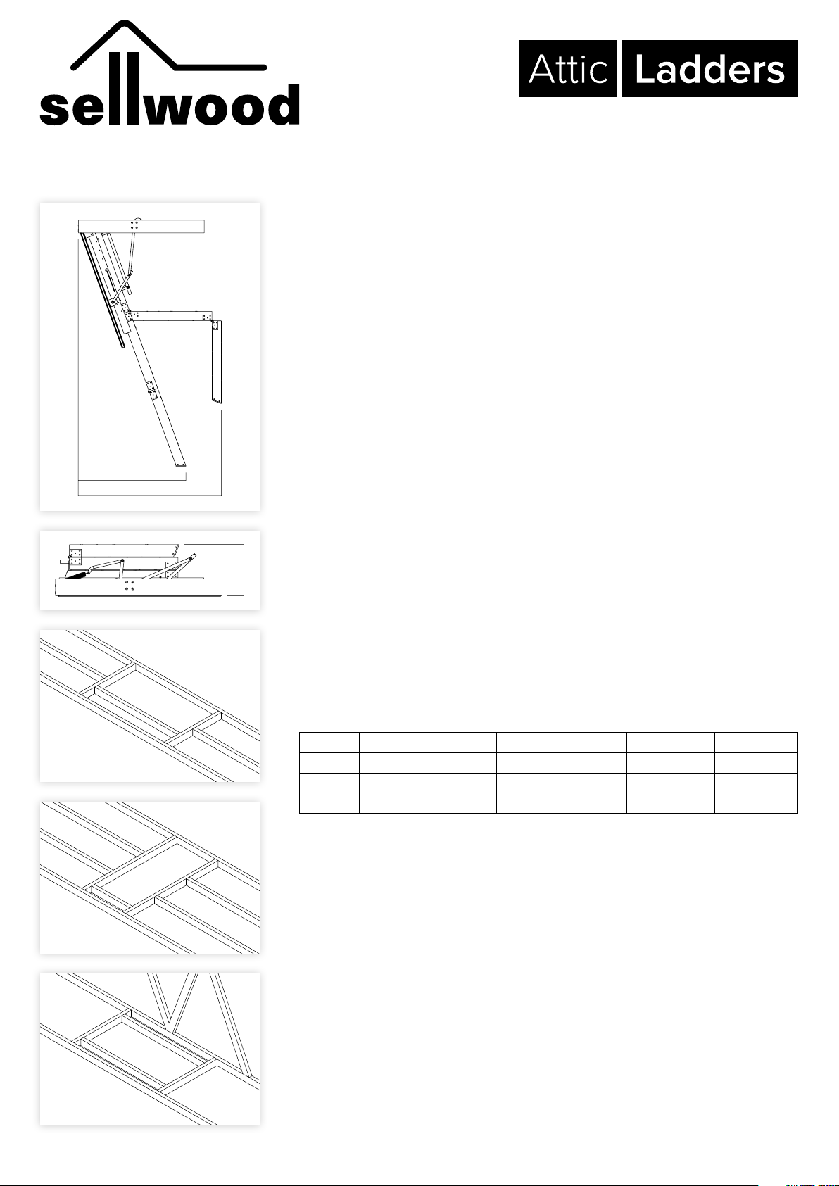
• Allowance must be made for the operation of the ladder, as it requires a greater
space to open than indicated by the opening in the ceiling (figure 1);
Model Required Opening Landing space Projection Stack
A25 1400mm x 650mm 1088mm - 1141mm 1517mm 423mm
A28 1400mm x 650mm 1180mm - 1232mm 1621mm 423mm
A36 1400mm x 650mm 1232mm - 1581mm 1777mm 529mm
• The area for the opening must be clear of wiring, plumbing and structural members
such as beams and trusses with a minimum stack height above the ceiling (figure 2).
Preparing The Opening
1. Mark out on the ceiling the opening required for the model ladder purchased in the
selected position. Cut out the ceiling lining ensuring that the opening is square.
2. Using timber of a compatible size to the existing ceiling framing (ie 90 x 45 or 140
x 45 H1.2 treated, machine gauged radiata pine), frame up the opening. It may
be necessary to cut through some existing ceiling joists to achieve the required
size. Ensure these are properly supported during and after cutting. Three possible
arrangements are shown in figures 3,4 & 5.
3. Do not cut trusses without engineering approval.
Installation Instructions
A25 | A28 | A36
figure 1
figure 2
figure 3
figure 4
figure 5
Landing Space
Projection
Stack
Preparing The Ladder
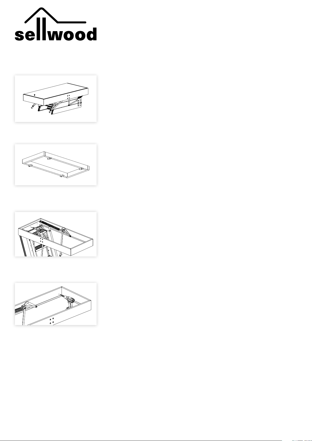
1. Remove the ladder from its packaging.
2. Place ladder on bench or saw stool with the lid facing up.
3. Fit the screw eye to the pre-drilled hole in lid (figure 6.)
Installing The Ladder
1. Screw four temporary cleats approx 80mm x 40mm into your timber frame as shown
in figure 7. Ensure cleats can be rotated.
The cleats must be securely fixed as they carry the full weight of the ladder.
Note: If the ladder is to be installed before the ceiling lining is in place, the cleats
must be packed down the thickness of the intended ceiling lining.
2. Lift the ladder through the opening into the attic space. Then lower down squarely
into the opening so the lid of the ladder rests on the temporary cleats. This is
normally best done from below. For safety and ease it is highly recommended that
two people complete this step. Rotate the cleats o the lid and onto the frame of the
ladder.
3. Check and confirm there is plenty of frame sitting on the cleats before proceeding
further. Adjust if necessary. The ladder must not be allowed to fall, as this could cause
serious physical injury.
4. Carefully open the ladder, checking that the frame remains securely on the cleats.
Adjust if necessary. Do not put any weight on the ladder at this stage.
5. From a step ladder or work platform (not the attic ladder), fix the hinge end of the
ladder to the ceiling framing through the predrilled holes in the hinge plate (figure 8).
Use the timbertight screws supplied. Do not fit tight yet.
6. Carefully close the ladder and check if square. Wedges or packers may be needed
at one side of the hinge strip to square the unit in the opening. This may require
reopening the ladder and loosening or tightening one of the screws a little.
7. With the ladder open, pre-drill two 6mm holes in each side of the attic ladder frame
making sure there is solid timber behind. Screw through the pre-drilled holes into the
ceiling frame (figure 9). Do not fit tight yet.
8. Remove temporary cleats.
9. Carefully close the ladder and check that the ladder frame is showing around the lid
evenly. Adjust the side fixings and fit packers as necessary between the ladder frame
and the ceiling frame. Make sure the sides stay plumb and straight.
10. Now tighten all screws and check again.
figure 6
figure 7
figure 8
figure 9

Adjusting The Ladder Height
Unfold the middle and bottom section.
A36 model - See below for extra instructions before proceeding.
1. Loosen the screws located through the slots where the top section is fitted to the
runner.
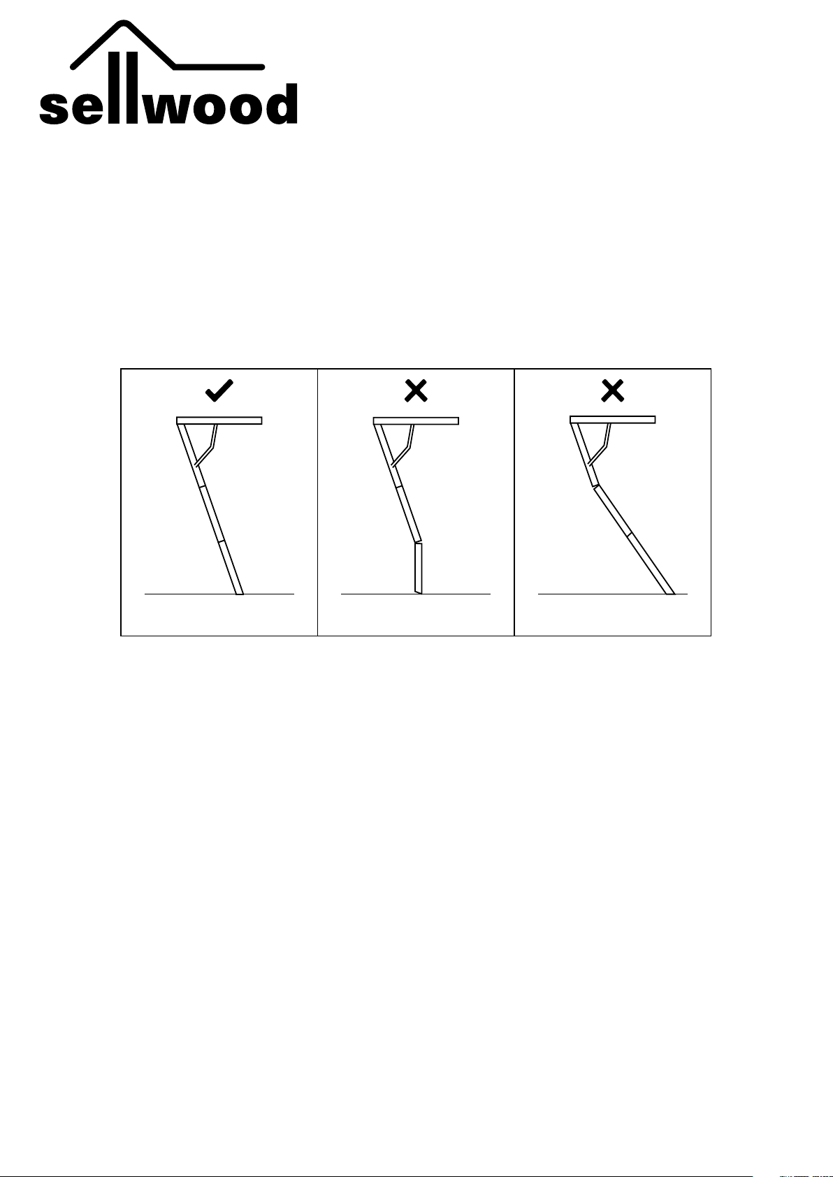
2. Slide the whole ladder down the runners until the rubber feet are firmly on the floor
and the ladder sections are closing tight where hinged. Once correctly adjusted to
height, tighten the screws in the slots of the runner.
3. Once the ladder has been adjusted to height, fix 2 x M6 bolts through both runners,
to lock the ladder in place.
4. There are 6 x empty holes on each runner, 3 at the top and 3 at the bottom. Choose
one hole at the top and one at the bottom of each runner to fit your M6 bolt through.
5. Drill a 6mm hole through the aluminium ladder stringer, using your chosen holes in
the runner as a guide. Make sure there are no treads in the way. Firmly fix 2 x M6
bolts through each runner to secure the ladder.
A36 model
Before completing steps 2 - 6 above, complete the following steps:
1. The A36 ladder covers a wide range of heights from 2.7m - 3.66m and may need
to be cut either in line with a tread or midway between treads before sliding to the
correct height.
2. Determine the exact ceiling height.
3. Use the table below and Figure 11 to determine the cut position:
Cut Position Ceiling height range
1 2700mm - 2780mm (Remove bottom section)
2 2780mm - 2915mm (Remove bottom section)
3 2915mm - 3025mm
4 3025mm - 3135mm
5 3135mm - 3250mm
6 3250mm - 3360mm
7 3360mm - 3470mm
8 3470mm - 3590mm
9 3590mm - 3660mm (Do not cut section)
4. Unfold the middle and bottom sections of the ladder. For Cut Position #1 & 2 - remove
the bottom section and hinge.
5. Based on your Cut Position, determine which tread you need to cut above or
measure to the midway point between the treads you need to cut between.
6. The ladder will need to be cut at the same angle as the treads at 70°.
7. After the ladder has been cut to height fit the rubber feet supplied in the packaging.
Drill a 6mm hole through the aluminium using the ladder foot holes as a guide.
Finishing The Ladder
1. Fix a suitable architrave around the lid (figure 12).
Note: The ladder is designed to be installed with the bottom of the frame flush with the
underside of the ceiling lining. An architrave will cover the gap between the ladder frame
and the ceiling lining while also hiding the edge of the lid from view (figure 13).
figure 11
figure 10
figure 12
figure 13
2
1
3
4
5
6
7
8
9
www.sellwood.co.nz
0800 288 427 (ATTICS)
3/75 Apollo Drive, Rosedale
HOW TO LOOK AFTER & USE YOUR SELLWOOD ATTIC LADDER
1. Before climbing, make sure the ladder is fully extended and that there
are no gaps between the ladder sections.
2. If your attic ladder has not been installed in accordance with the
manufacturer’s installation instructions your warranty may be void.
3. Lubricate all pivot points on your attic ladder at least once a year.
If your attic ladder is used more than three times a week, lubricate
every 4-5 months.
4. Face the ladder when you are climbing up and down.
5. Do not leave young children unattended while ladder is folded down.
6. If you have any concerns about your Sellwood attic ladder, or it is
damaged in any way please call 0800 288 427.
GapNo Gap
No Gap
Too ShortFlush with Floor Too Long
Gap
This manual suits for next models
2
Table of contents
Other sellwood Ladder manuals


Popular Ladder manuals by other brands


Canbuilt
Canbuilt NH Series Assembly and user's guide

Amstel
Amstel A25 installation instructions

SCALANT
SCALANT SCARLO 1000 Assembly instructions

Xtend+Climb
Xtend+Climb HOME 750P PLUS Operational and care instructions

Profi-Partner
Profi-Partner 49461 Instructions for use and Safety Instructions

Primal
Primal PVLS-600 Instruction and safety manual


