Important
Strong springs aid the operation of these ladders! Care must be exercised during
installation and operation so these springs are not released in an uncontrolled manner as
this could lead to damage to the ladder and personal injury to the operator/installer.
These instructions are not intended to be a complete lesson in the installing of attic
ladders but a procedural guide to competent tradespeople or DIYers.
Tools Required
The timbertight screws supplied with this ladder require a 5/16” socket for easy
installation. Apart from this, only standard carpentry tools are required.
Choosing The Location
When choosing the location for the installation of the attic ladder, a compromise between
where you would like it to be located in relation to the floor plan and what is possible in
relation to the roof structure may be required. The considerations for this compromise are:
• Choose a location that will give good head room at the top of the ladder;
• Choose a location with good access at the bottom of the ladder;
• Choose a location that will allow for movement around the ladder when in the down
position;
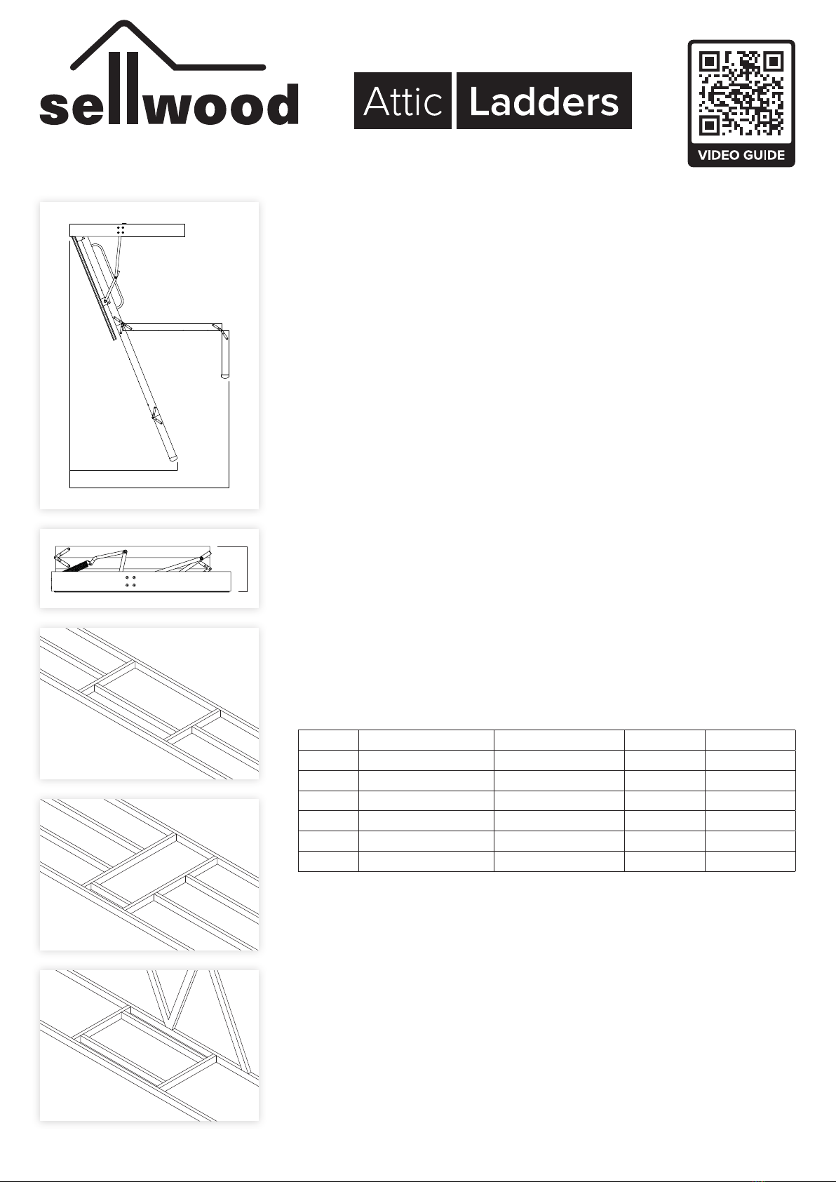
• Allowance must be made for the operation of the ladder, as it requires a greater
space to open than indicated by the opening in the ceiling (figure 1);
Model Required Opening Landing space Projection Stack
P30 1300mm x 600mm 1095mm - 1414mm 1770mm 320mm
P36 1300mm x 600mm 1418mm - 1667mm 1763mm 410mm
D28 1400mm x 650mm 1337mm - 1634mm 1854mm 400mm
D30 1450mm x 650mm 1362mm - 1770mm 1994mm 400mm
D36 1450mm x 650mm 1770mm - 2055mm 1995mm 525mm
Q24 835mm x 650mm 1005mm - 1076mm 1238mm 420mm
• The area for the opening must be clear of wiring, plumbing and structural members
such as beams and trusses with a minimum stack height above the ceiling (figure 2).
Preparing The Opening
1. Mark out on the ceiling the opening required for the model ladder purchased in the
selected position. Cut out the ceiling lining ensuring that the opening is square.
2. Using timber of a compatible size to the existing ceiling framing (ie 90 x 45 or 140
x 45 H1.2 treated, machine gauged radiata pine), frame up the opening. It may
be necessary to cut through some existing ceiling joists to achieve the required
size. Ensure these are properly supported during and after cutting. Three possible
arrangements are shown in figures 3, 4 & 5.
3. Do not cut trusses without engineering approval.
Stack
Landing Space
Projection
figure 1
figure 2
figure 3
figure 4
figure 5
Installation Instructions
P30 | P36 | D28 | D30 | D36 | Q24


